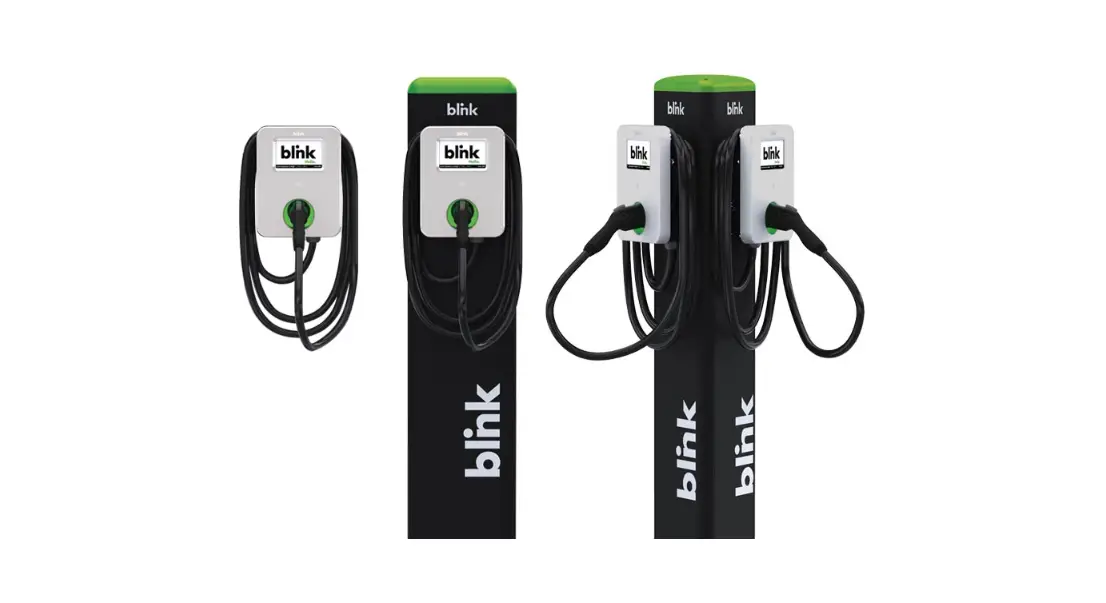
blink Fast IQ 200 Level 2 EV Charger
Contact your lighting representative at i[email protected]
P: 754.702.2709
© 2019 by Blink Network, LLC
No part of the contents of this document may be reproduced or transmitted in any form or by any means without the express written permission of Blink Network, LLC. The contents of this document have been verified by the manufacturer to be consistent with the described components; however, inconsistencies sometimes occur. Such inconsistencies should be brought to the attention of an Blink Network, LLC representative. Changes to this manual may be made at any time without notice.
Disclaimer of Consequential Damages
Blink Network, LLC is not responsible for the use or application by any person of the materials in this manual. Blink Network, LLC is not responsible for damages, either direct or consequential, arising out of or relating to the use or application of these materials.
Notice
Changes or modifications not expressly approved by the party responsible tor compliance could void the user’s authority to operate the equipment.
Blink, Blink Network, and the Blink logo are registered trademarks of Blink Network, LLC.
SAE J1772 M is a trademark ot SAE International
Blink Network, LLC 4141 E.
Raymond St. Suite D
Phoenix, AZ 85040
1-888-998-BLINK (2546)
www.blinkcharging.com
IMPORTANT SAFETY INSTRUCTIONS
Before installing or using the Blink Network, LLC (Blink) electric vehicle supply equipment (EVSE), read all these instructions, paying particular attention to any WARNING and CAUTION markings in this document and on the Blink Product. You should also review any instructions included with your electric vehicle (EV) as they pertain to vehicle charging.
The following symbols and associated instructions are used throughout this document and relate to action necessary to avoid hazards.
Safety Instructions
Legend
![]() WARNING
WARNING
Used when there is a risk of personal injury
![]() WARNING: RISK OF ELECTRIC SHOCK Used when there is a risk of electric shock
WARNING: RISK OF ELECTRIC SHOCK Used when there is a risk of electric shock
![]() WARNING: RISK OF FIRE Used when there is a risk of fire
WARNING: RISK OF FIRE Used when there is a risk of fire
![]() CAUTION
CAUTION
Used when there is a risk of damage to the equipment
- This product should be installed only by a qualified approved technician.
- Blink is not responsible for physical injury, damage to property or equipment caused by the installation of this device.
- A device employing pressure terminal connectors for field wiring connections shall be provided with instructions specifying a range of values or a nominal value of tightening torque to be applied to the clamping screws of the terminal connectors.
- Make sure that the materials used and the installation procedures follow local building codes and safety standards.
- The information provided in this manual in no way exempts the user of responsibility to follow all applicable codes or safety standards.
- Review this manual carefully and consult with a licensed contractor, licensed electrician, or trained installation expert to make sure of compliance with local building codes and safety standards.
Repair and Maintenance Clause
- Only a licensed contractor, licensed electrician, or trained installation expert is allowed to repair or maintain this device.
It is forbidden for a general user to repair or maintain this device. - Any repair or maintenance MUST be performed after removing power from this device.
FCC Rules and Industry Canada License-Exempt RSS Standard(s)
- This device complies with Part 15 of the FCC Rules. Changes or modifications are not expressly approved
This device complies with Industry Canada license-exempt RSS standard(s).
Operation is subject to the following two conditions:
- this device may not cause interference, and
- this device must accept any interference, including interference that may cause undesired operation of the device.
WARNING: RISK OF ELECTRIC SHOCK
Basic precautions should always be followed when using electrical products, including the following:
- Read all the instructions before using this product.
- This device should be supervised when used around children.
- Do not put fingers into the EV connector.
- Do not use this product if the flexible power cord or EV cable is frayed, has broken insulation, or any other signs of damage.
- Do not use this product if the enclosure or the EV connector is broken, cracked, open, or shows any other indication of damage.
WARNING: RISK OF ELECTRIC SHOCK
Improper connection of the equipment grounding conductor can result in a risk of electric shock. Check with a qualified electrician or serviceman if you are in doubt as to whether the product is properly grounded.
WARNING: RISK OF ELECTRIC SHOCK
- Do not touch live electrical parts.
- Incorrect connections may cause electric shock.
WARNING
This equipment is intended only for charging vehicles that do not require ventilation during charging.
Please rater to your vehicle’s owner’s manual to determine ventilation requirements.
WARNING
Do not use extender cables to increase the length of the charging cable.
The maximum length is limited to 25 feet by the National Fire Protection Agency.
General Conventions
The use of the word Note: indicates additional information that is relevant to the current process or procedure.
SAVE THESE INSTRUCTIONS
INTRODUCTION
This Instruction Manual describes how to properly install the Blink IQ 200 Level 2 AC EVSE (Blink Product). Contact the Blink Support Center at 1-888-998-BLINK (2546) for troubleshooting assistance and additional technical questions.
Unauthorized modification of the Blink Product
The Blink Product specified in this document is design for the North American market to charge plug-in electric vehicles (PEVs), plug-in hybrid electric vehicles (PHEVs), and battery electric vehicles (BEVs). It provides Level 2 AC charging that shortens the charging time for typical EVs, when compared to a Level 1 AC EVSE.
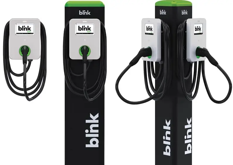
PRODUCT OVERVIEW
| BLINK IQ 200 PRODUCTS | |||
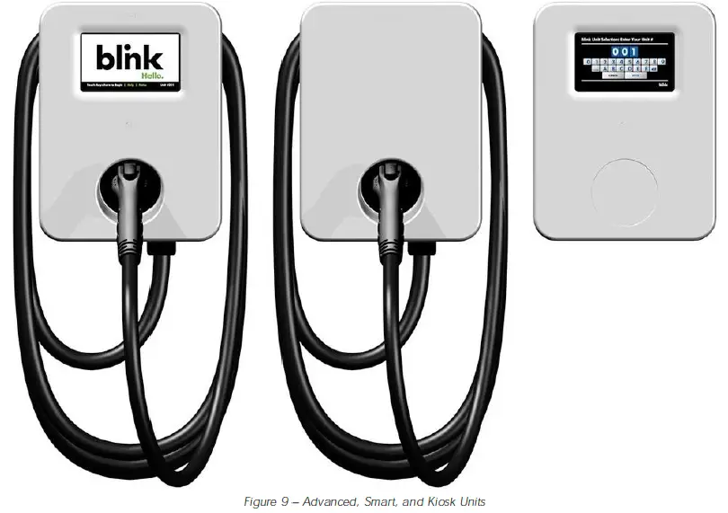
| MODEL NAME | ADVANCED CHARGING STATION | SMART CHARGING STATION | KIOSK |
| MODEL NUMBER | IQW2 -80U-M1-R2-N -25 | IQW2 -80U-W1 -N1 -N -25 | IQW2 -00U-M1-R2-N -00 |
| PART NUMBER | 01-0207 | 01-0205 | 01-0208 |
| PRODUCT VIEW | 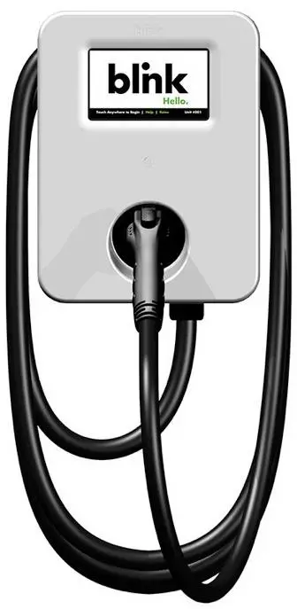 | 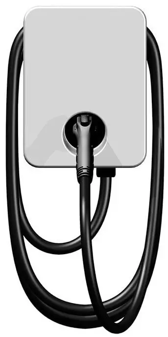 | 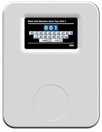 |
PRODUCT SPECIFICATIONS
| BLINK IQ 200 PRODUCTS | |||
| POWER SPECIFICATIONS | ADVANCED CHARGING STATION | SMART CHARGING STATION | KIOSK |
| Input/ Output Power (Max.) | 19.2kW Max. | 19.2W Max. Input Only | |
| Input/ Output Power (Standby) | <10W Standby | <10W Standby | |
| Input/ Output Power | 2.9, 3.8, 5.8, 7.7, 9.6, 15.4, 17.3, 19.2kW | 19.2W Max. Input Only | |
| Input/ Output Amperage | Software Selectable:12A, 16A, 24A, 32A, 40A, 64A, 72A, 80A | 0.08A Continuous Input Only | |
| Circuit Breaker Options | 15A, 20A, 30A, 40A, 50A, 80A, 90A, 100A | 15A or 20A | |
| Input/ Output Voltage | 208VAC/ 240VAC | 120/ 208/ 240VAC Input | |
| Input / Output Voltage Range | 180VAC to 264VAC | 90 to 132VAC, 180 to 264VAC Input | |
| Input / Output Frequency | 60Hz | ||
| Input Wiring Type | Hardwired | ||
| Input Wiring Scheme | L1, L2, GND | L1, N, GND or L1, L2, GND | |
| Cold-Load Pickup | Randomized delay between 120 and 720 sec. before charge resumes after a power failure. | Not Applicable | |
| Power Measurement Accuracy | Embedded meter with a ±1% accuracy at the nominal input. | Not Applicable | |
| Surge Protection | Up to 6kV at 3,000A | ||
| FUNCTIONAL SPECIFICATIONS | |||
| Charge Connector Type | SAE J1772 | Not Applicable | |
| Charge Cable Length | 25ft. | Not Applicable | |
| Demand Response | Yes2 | Not Applicable | |
| Status Indicator | LED and Audio | Audio | |
| User Interface | None1 | ||
| Access Control | Contactless Reader: RFID Cards: ISO/ IEC 14443A/ B, ISO/ IEC 15693, MIFARE Plus, HID iCLASS, NEMA Smart Credit Cards2:Visa, Master Card, Discover, American Express NFC2: ISO 18092, Apple Pay, Google Pay | None1 | Contactless Reader: RFID Cards: ISO/ IEC 14443A/ B, ISO/ IEC 15693, MIFARE Plus, HID iCLASS, NEMA Smart Credit Cards2:Visa, Master Card, Discover, American Express NFC2: ISO 18092, Apple Pay, Google Pay |
| NETWORK SPECIFICATIONS | |||
| Local Area Network (LAN) | 2.4GHz Wi-Fi (802.11 b/ g/ n) | ||
| Wide Area Network (WAN) | Cellular (3G GSM, 3G CDMA) | None | Cellular (3G GSM, 3G CDMA) |
| Network Interface | Blink OCPP, OCPP v1.6J | ||
| Mounting Type | Pedestal or Wall Mount | ||
| SAFETY & COMPLIANCE SPECIFICATIONS | |||
| Ground Fault Detection | CCID20, 20mA per UL 2231, Automatic Reset Feature and Manual Reset Feature | Not Applicable | |
| Ground Monitor | Ground Monitor per UL 2231 | Not Applicable | |
| Safety Compliance | UL and cUL, NEC Article 625, RoHS, Norma Oficial Mexicana (NOM) | ||
| Protection | Over-Voltage (OVP), Under-Voltage (UVP), Over-Current (OCP), Over-Temperature (OTP), and Short-Circuit Protection | ||
| EMC Compliance | FCC Part 15 Class B, Industry Canada (IC), PTCRB | ||
| ADA Compliance | Yes | ||
| ENERGY STAR Certified | Yes | Not Applicable | |
| OPERATIONALSPECIFICATIONS | |||
| Enclosure Rating | NEMA Type 3R Indoor/ Outdoor | ||
| Operating Temperature | -30°C to +50°C (-22°F to +122°F) | ||
| Storage Temperature | -40°C to +80°C (-40°F to +176°F) | ||
| Operating Humidity | 0 to 95% Relative Humidity, Non-Condensing | ||
| Charger Dimensions | |||
| Package Dimensions | |||
| Charger Weight (Unpackaged) | 25.3lbs. (11.5kg) | 24.2lbs. (11kg) | 8.8lbs. (4kg) |
| Charger Weight (Packaged) | 31lbs. (14kg) | 30lbs. (13.6kg) | 10lbs. (4.5kg) |
PRE-INSTALLATION INSTRUCTIONS
Safety and Grounding
Safety Check
CAUTION: DISCONNECT ELECTRICAL POWER PRIOR TO INSTALLING THE BLINK CHARGING STATION. FAILURE TO DO SO MAY CAUSE PHYSICAL INJURY OR DAMAGE TO THE ELECTRICAL SYSTEM AND BLINK PRODUCT.
The Blink Product should be installed only by a licensed contractor, and/or a licensed electrician in accordance with all applicable state, local and national electrical codes and standards.
Before installing the Blink Product, review this manual carefully and consult with a licensed contractor, licensed electrician and trained installation expert to ensure compliance with local building practices, climate conditions, safety standards, and state and local codes.
Use appropriate protection when connecting to the main power distribution cable. Use tools as outlined in the “Tools Required for Installation” section.
Grounding Instructions
This product must be connected to a grounded, metal, permanent wiring system; and an equipment grounding conductor must be run with the circuit conductors and connected to the equipment grounding terminal or lead on the product.
Conduit & Breaker Size Guide
| All Specifications are Per Charging Station or Port | |||||
| Max. Output (Charging) Current | Typical Circuit Breaker (CB)3 | Typical Wire Specs3 | Typical Conduit Size3 | Blink IQ 200 Enclosure Input Conduit Size | Notes / Assumptions |
| 12A See Note Below | 15A | Two #12AWG Wires (Line) One #12AWG Wire (Ground) | 1/ 2″ | -Way Distance | |
| 16A See Note Below | 20A | Two #10AWG Wires (Line) One #12AWG Wire (Ground) | 3/ 4″ | -Way Distance
| |
| 24A See Note Below | 30A | Two #8AWG Wires (Line) One #10AWG Wire (Ground) | 3/ 4″ | -Way Distance | |
| 32A See Note Below | 40A | Two #8AWG Wires (Line) One #10AWG Wire (Ground) | 3/ 4″ | -Way Distance | |
| 40A See Note Below | 50A | Two #6AWG Wires (Line) One #8AWG Wire (Ground) | 3/ 4″ | -Way Distance | |
| 64A See Note Below | 80A | Two #4AWG Wires (Line) One #8AWG Wire (Ground) | One-Way Distance | ||
| 72A See Note Below | 90A | Two #3AWG Wires (Line) One #8AWG Wire (Ground) | -Way Distance | ||
| 80A Default Setting | 100A | Two #2AWG Wires (Line) One #8AWG Wire (Ground) | -Way Distance | ||
Consult with a licensed contractor, licensed electrician, or trained installation expert to ensure compliance with local building codes and safety standards.
Table 1 Conduit and Breaker Size Guide
![]() CAUTION
CAUTION ![]() WARNING: RISK OF FIRE
WARNING: RISK OF FIRE
All charging products are preconfigured to allow a Max. Output (Charging) Current of 80A. product at a reduced current, the Max Amperage FW Setting MUST be configured using the unit’s Web Portal (See Instructions in Section 7.2 Changing the Maximum Output (Charging) Current of a Charging To operate the Station).
![]() CAUTION
CAUTION ![]() WARNING: RISK OF FIRE
WARNING: RISK OF FIRE
To reduce the risk of the fire, connect only to a circuit provided with (CB Table 1) amperes maximum branch circuit overcurrent protection in accordance with the National Electrical Code, ANSI/NFPA 70, and the Canadian Electrical Code, Part I, C22.2.
Mounting Options
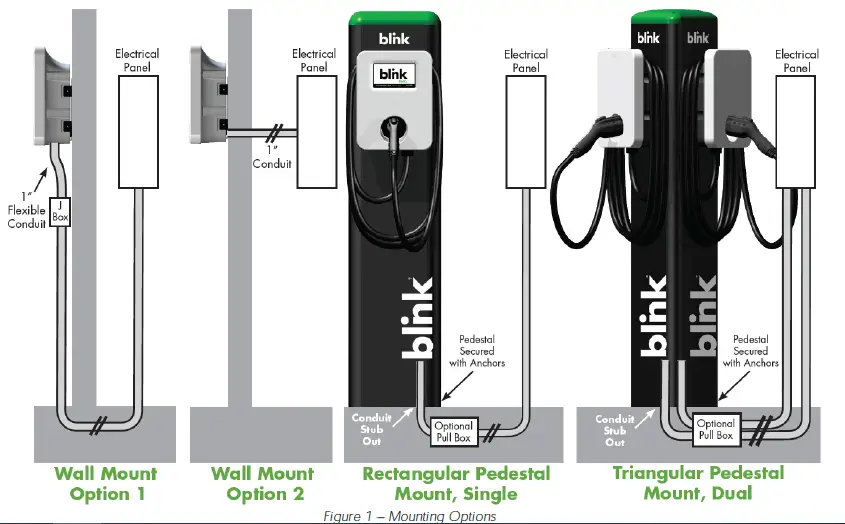
Product Placement Tips
Kiosk and Smart Unit Placement
- Kiosk units should be installed within 150ft. (line-of-sight) of the farthest Smart unit.
- Walls, pillars, and barriers may affect the ability for a Smart unit to communicate with a Kiosk unit.
- Kiosk can provide access control for up to 20 secondary Smart Charging Stations.
Advanced and Kiosk Unit Placement
- Advanced and Kiosk units which will be utilizing cellular connections to communicate with a Central System must be installed in an area that has adequate cellular coverage.
- Enclosed and/or underground structures, such as parking garages may not support adequate cellular coverage. In these cases, cellular repeater / amplifier systems should be considered.
INSTALLATION INSTRUCTIONS
Tools Required for Installation
| Tool | Applicable Models | Supplier Name | Supplier Part # |
| Security Torx T20 L-Driver | All Product Models | Blink | Included in Product Box |
| Security Torx T20 Driver | All Product Models | Commercially Available | Commercially Available |
| Wire Cutters | All Product Models | Commercially Available | Commercially Available |
| Wire Strippers | All Product Models | Commercially Available | Commercially Available |
| Channellock Pliers | All Product Models | Commercially Available | Commercially Available |
| Torque Wrench | All Product Models | Commercially Available | Commercially Available |
| Drill | All Product Models | Commercially Available | Commercially Available |
| Drill Bits | All Product Models | Commercially Available | Commercially Available |
| Slotted Screwdriver | All Product Models | Commercially Available | Commercially Available |
| P2 Phillips Screwdriver | Kiosk Model | Commercially Available | Commercially Available |
| P3 Phillips Screwdriver | Advanced & Smart Models | Commercially Available | Commercially Available |
| Crimpers, 12-14 AWG | Kiosk Model | Commercially Available | Commercially Available |
| Crimpers, 8-4/ 0 AWG | Advanced & Smart Models | Greenlee | K09-2GL |
Table 2 Tools Required for Installation
Parts Required for Installation
| Part | QTY | Applicable Models | Supplier |
| Product | 1 | All Product Models | Blink, Included in Product Box |
| Mounting Bracket | 1 | All Product Models | Blink, Included in Product Box |
| Mounting Bolts To Secure the EVSE to the Mounting Bracket | 4 | All Product Models | Blink, Included in Product Box |
| Ring Terminal, 2 AWG, Power Terminals | 2 | Advanced & Smart Models | Blink, Included in Product Box |
| Ring Terminal, 8 AWG, Power Terminals | 2 | Advanced & Smart Models | Blink, Included in Product Box |
| Ring Terminal, 8 AWG, Ground Terminal | 1 | Advanced & Smart Models | Blink, Included in Product Box |
| Ring Terminal Insulators, Vinyl End Caps | 5 | Advanced & Smart Models | Blink, Included in Product Box |
| Wire, Copper | As Needed | Commercially Available | Commercially Available |
| Wall Mount Only | 2 | Commercially Available | Commercially Available |
| Wall Mount Only | 4 | Commercially Available | Commercially Available |
| Wall Mount Only | 1 | Commercially Available | Commercially Available |
| Wall Mount Only | As Needed | Commercially Available | Commercially Available |
Table 3 Parts Required for Installation
Installation Procedure
Open the Blink Product box and locate the mounting bracket.
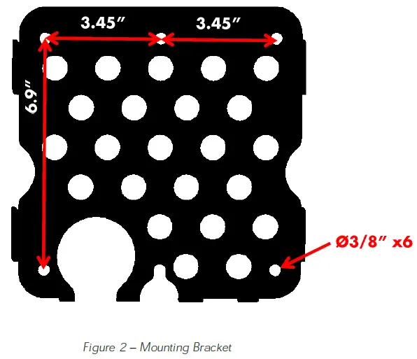
Drill holes in the wall or mounting surface for the mounting bolts.
Note: A recommended mounting height is 40 inches (1016 mm) from finish grade to the bottom of the mounting bracket.
Note: Follow applicable accessibility requirements for the mounting position. This equipment should be located at least 18 inches (460 mm) above the floor.
Secure the mounting bracket to the wall or mounting surface with appropriate fasteners as follows:
- For metal construction, Use 5/16 Screws or bolts.
- For wood construction, use 5/16″ lag bolts.
- For masonry walls, use 5/16″ expansion anchors.
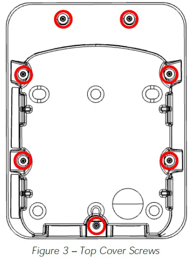
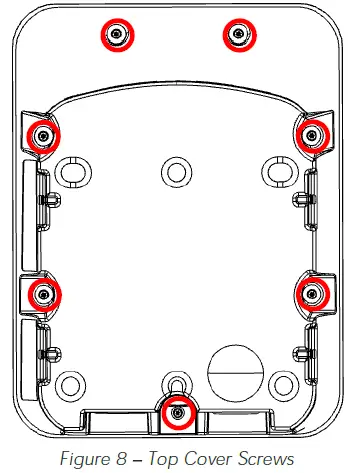
Remove the top cover from the Blink Product using a Security T20 driver to loosen the 7 screws.
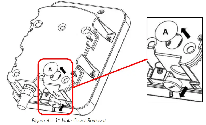
Remove the appropriate 1″ hole cover (A or B) based on the desired conduit entry point.
Attach the l” conduit (with wire) to the enclosure using the appropriate 1″ conduittitting.
Note: Choose the appropriate conduit and wire based on Table 1 Conduit and Breaker Size Guide and in accordance with all applicable state, local, and national electrical codes and standards. Use conductor type other than RHH, RHW and RHW-2.
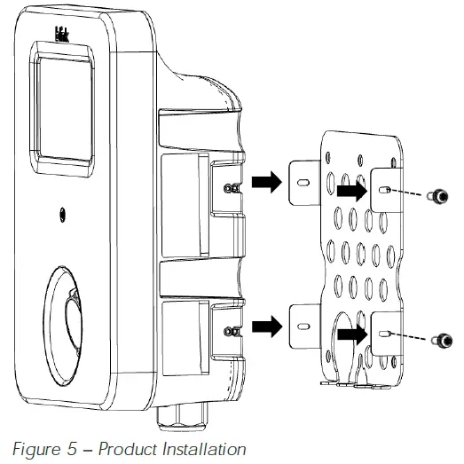
Attach the product to the mounting bracket using the 4 included mounting bolts and a Security T20 Driver using a torque force of 13 Inch-Pounds (1.5 Newton Meters).
CAUTION
Do not overtighten the mounting bolts as damage may occur.
Using the appropriate wire stripping tool and crimping tool specified in Table 2 Tools Required for Installation, crimp the included ring terminals to the wires.
Tip: The recommended wire strip length is 5/8″.
![]() CAUTION
CAUTION ![]() WARNING: RISK OF FIRE
WARNING: RISK OF FIRE
Failure to use the proper crimping tool could result in a fire and/or damage to the equipment. Proper crimping tools and crimping methods MUST be used. Blink Product installers may be held liable for the improper installation of a unit, which includes the use of improper crimping tools and methods.
Slide the included Vinyl End Caps over the crimped ring terminals.
Remove the clear plastic cover from the terminal block.
Attach the crimped ring terminals to the terminal block inside the Blink Product.
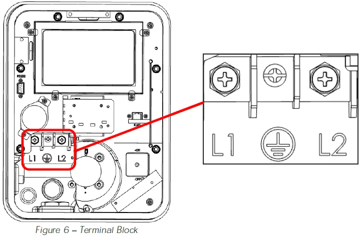
Ensure that the terminal block bolts are tightened using the following torque specifications:
Advanced and Smart Models
- L1 and L2: 70 Inch-Pounds (8 Newton-Meters)
- Ground: 26 Inch-Pounds (3 Newton-Meters)
Kiosk Model
- L1 and L2: 7 Inch-Pounds (0.8 Newton Meters)
- Ground: 7 Inch-Pounds (0.8 Newton Meters)
![]() CAUTION
CAUTION ![]() WARNING: RISK OF FIRE
WARNING: RISK OF FIRE
Failure to use the proper torque specs could result in a fire and/or damage to damage to the equipment. Proper torque tools and methods must be used. Blink Product installers may be held liable for the improper installation of a unit, which includes the use of improper torque tools and methods.
Re-attach the clear plastic cover to the terminal block.
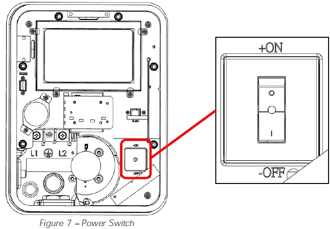
Turn the power switch rom the “OFF” position to the “ON” position.
Re-attach the top cover to the Blink Product using a Security T20 Driver and a torque force of 13 Inch-Pounds (1.5 Newton Meters).
CAUTION
Do not overtighten the mounting bolts as damage may occur.
Apply power to the Blink Product.
If applicable, coil the charge cable around the Blink Product and attach the charging connector to the holster.
SETUP INSTRUCTIONS
Web Portal Access
- Contact the Blink Network Support Center at 1-888-998-BLINK (2546) to obtain the Wi-Fi password AND the Web Portal password.
- Using a computer, a tablet, or a smartphone that supports Wi-Fi, browse for available networks.
- Connect to the Blink Product’s WiFi network by selecting the SSID (Wi-Fi Network Name) which corresponds with unit’s serial number (displayed on the left side of the unit).
TIP: The format of the Wi-Fi Network name will be Blink-Serial Number Example: Blink-L1-0207-1638-123456 - Enter the Wi-Fi password and connect to the Wi-Fi network.
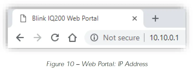
- Open a web browser (such as Google Chrome, Mozilla Firefox, Safari, etc.) and navigate to the following IP address: 10.10.0.1
- In the User Name field, enter admin.
- In the Password field, enter the password that you received from the Blink Network Support Center.
Changing the Maximum Output (Charging) Current of a Charging Station
IMPORTANT: The maximum output (charging) current of the Blink Product must only be adjusted by authorized personnel. The maximum output (charging) current must not be adjusted after the Blink Product is commissioned.
If a circuit breaker is upgraded at a later time, the Blink Product must be re-commissioned and the maximum output (charging) current must be adjusted at that time by authorized personnel.
On the Configuration page of the unit, select the Station Settings tab.
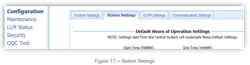
On the Station Settings tab, enter the Maximum Charging Current in the Max Amperage FW Setting field. The amperage value should be a number that is in the following range: 12.0 to 80.0.
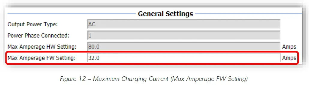
| Circuit Breaker Size | 15A | 20A | 30A | 40A | 50A | 80A | 90A | 100A |
| Max Amperage FW Setting | 12.0 | 16.0 | 24.0 | 32.0 | 40.0 | 64.0 | 72.0 | 80.0 |
Table 4 Maximum Charging Current (Max Amperage FW Setting)
Connecting a Smart Unit to a Kiosk (Smart Units Only)
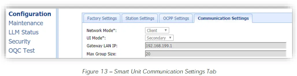
On the Configuration page of the Smart Unit, select the Communication Settings tab.
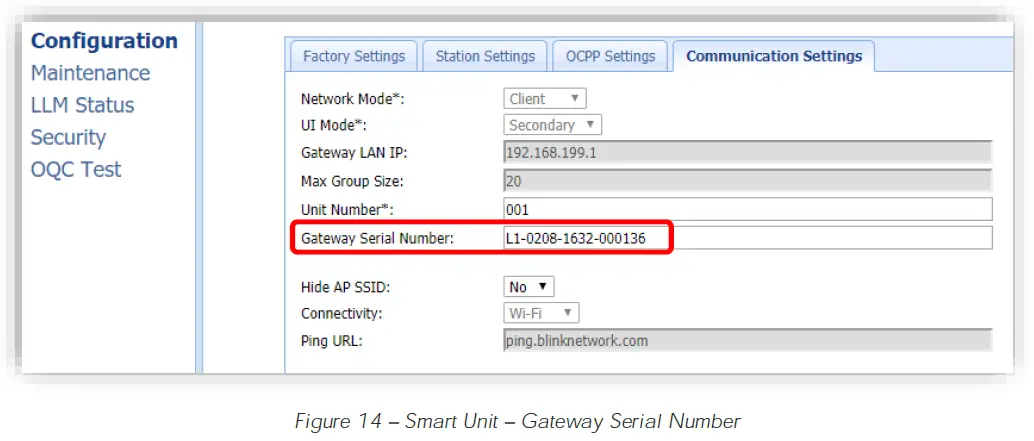
On the Communication Settings tab, enter the Serial Number of the Kiosk in the Gateway Serial Number field. The Serial Number of the Kiosk can be found on the product label on the left side of the unit.
Select the Apply button at the bottom of the page.
Repeat steps 7.1.2 through 7.3.3 for each Smart unit that needs to be connected to the Kiosk.
OPERATING INSTRUCTIONS
Starting a Charge Session
- Release the charging connector from the holster and connect it to the EV.
- Touch the Main Screen to begin the authorization process.
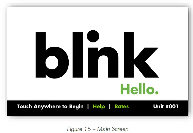
- Kiosk Only: Enter the Unit # of the charging station then touch ENTER.
The Unit # of a charging station is located on a label on the right side of the unit.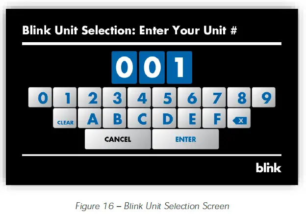
- Initiate a charge session using one of the following authorization methods:
- RFID Card
- Remote Start Command (Using a Mobile App)
- Blink Code (If Applicable)
- Smart Credit Card / Apple Pay / Google Pay (May not be included in the initial product offering)
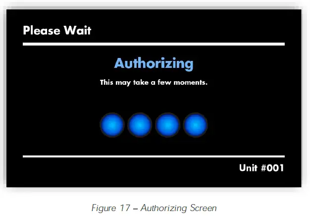
- The Authorizing screen will appear while the unit communicates with the Central System.
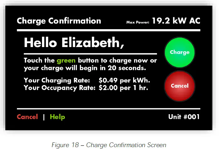
- Once the Charge Confirmation screen appears, select the Charge button. If a selection is not made within 20 seconds, the unit will automatically advance to the next screen.
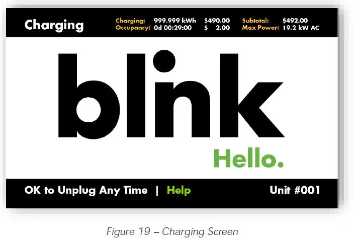
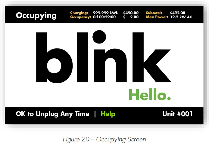
- While the EV is being charged, the Charging screen will be displayed.
- While the EV is connected but not being charged, the Occupying screen will be displayed.
Stopping a Charge Session
- Disconnect the charging connector from the EV at any time to stop the charge session.
- Once the session has been stopped, the Cost Summary screen will appear (if applicable).
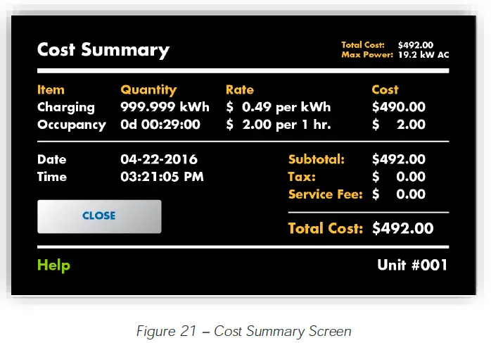
- Touch the CLOSE button or wait until the screen times out. The Session Ended screen will appear.
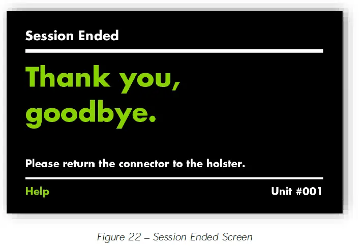
- Next, the Main Screen will appear.
Status Indicator
| Status Indicator | Description | Definition |
 | Not Illuminated | Power is OFF |
 | Flashing Yellow | Device is Not Ready (i.e. Booting, Upgrading Firmware, etc.) |
 | Steady Yellow | Device is Unavailable (i.e. Out of Service) |
 | Steady Green | Device is Available |
 | Flashing Green (Fast) | Device is Authorized and Ready to Charge |
 | Flashing Green (Slow) | Device is in State B (Vehicle is Occupying) |
 | Flashing Blue (Slow) | Device is in State C (Vehicle is Charging) |
 | Steady Red | Power On Self-Test Fault |
 | Flashing Red (Slow) | Warning / Fault |
Table 5 Status Indicator
CONFIGURATION
Factory Settings
- Initially, the Factory Settings tab will appear, which reflects the items which have been configured at the factory.
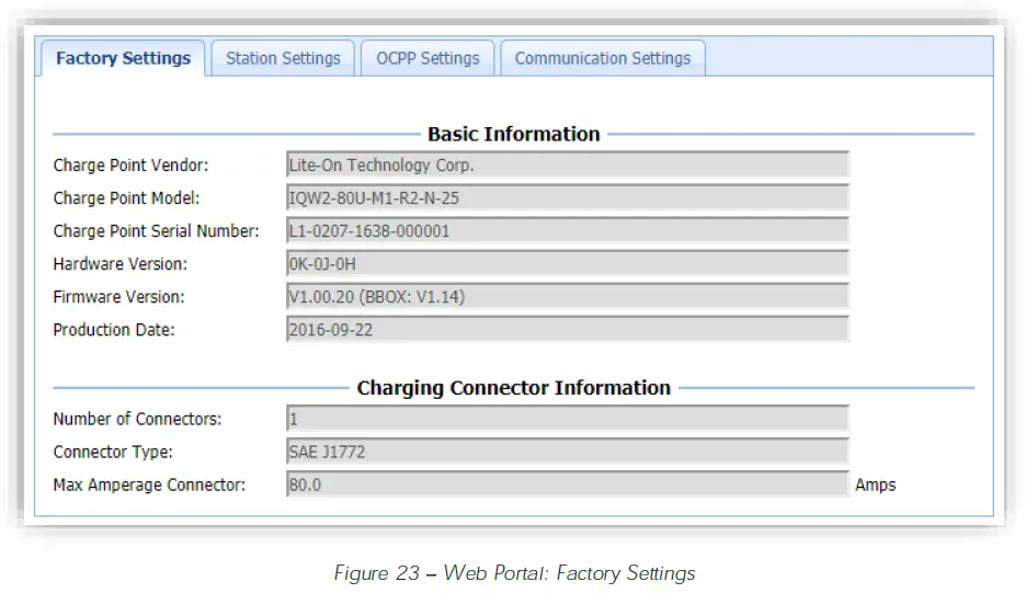
- The following table provides an overview of each item.
| Configuration Item | Description |
| Charge Point Vendor | The name of the Blink Product Vendor. |
| Charge Point Model | The Model Number of the Blink Product. |
| Charge Point Serial Number | The unique Serial Number of the Blink Product. |
| Hardware Version | The Hardware Version of the Blink Product. |
| Firmware Version | The Firmware Version of the Blink Product. |
| Production Date | The Production Date of the Blink Product. |
| Number of Connectors | The number of connectors associated with the Blink Product. |
| Connector Type | The type of charge connector. |
| Max. Amperage Connector | The maximum current output for the Blink Product. |
Station Settings
| Configuration Item | Description |
| Default Hours of Operation Settings | |
| Default Hours of Operation Settings | The default Hours of Operation. Settings sent from theCentral System will supersede these default settings. |
| Warning Settings | |
| Temperature Low | The value in Celsius at which the charger will send a low temperature warning. |
| Temperature High | The value in Celsius at which the charger will send a hightemperature warning. |
| Voltage Low | The value at which the charger will send a low voltage warning. |
| Voltage High | The value at which the charger will send a high voltage warning. |
| General Settings | |
| Output Power Type | The output power type of the BlinkProduct. |
| Power Phase Connected | The power phase configuration of the Blink Product. |
| Max Amperage HW Setting | The maximum current output for the Blink Product. |
| Max Amperage FW Setting | The configurable (and de-ratable) maximum current for the Blink Product. |
| PWM Amperage | The amperage used by the PWM interface connected to the EV. |
| Real Amperage | The real-time measured amperage. |
| Cold Load Pickup Max Delay | The maximum delay (in seconds) before a charging session is resumed after power reapplied after a power outage. The value is configurable between 120 and 720 seconds. |
| EV Connect Timeout | The interval (in seconds) after a successful authorization that a user has taottach the charge connector to their EV before the charge session is cancelled. |
| Plug and Charge ID | If the value is present,the Blink Productneeds to support plug and charge scenario by using the specific identifier. If the value isabsent, authorization for each session is required. |
| Offline Authorize | Specifies whether users can initiate a charge session using the contactless read (i.e. RFID Card) while a unit is offline. |
| Authorize Timeout | The interval (in seconds) that the Blink Product will attempt to connect to the Central Syste before an offline session is authorized OR cancelled (depending on the Offline Authoriz setting). |
| Reservation Supported | This setting is reserved for future use. |
| Resume Charge After Reboot | Indicates if the Blink Product will resume the charge session after a power cycle. If the settin is On, the charge session will resume according to UL regulations. If the setting iOsff, the charge session will not resume after a power cycle. |
| Dim Option | The interval (in minutes) of touch screen inactivity before the LCD reduces its brightness bas on the Dim Intensity setting. If touch screen activity is detected, the LCD will display using maximum brightness setting. |
| Dim Intensity | The percentageof the maximum LCD brightness which will apply if the Dim Option is enabled If 0% is selected, the display will be turned off after the Dim Option time interval. |
| Odometer Screen | Indicates if the Odometer Screen will be displayed to users during the auothrization process. This setting primarily applies to fleet applications. |
| Time Zone | The local time zone of the Blink Product. |
| Default Price Settings | |
| Default Pricing Settings | The default Price Settings. Settings sent from the Central System wsiull persede these default settings. |
| GPS Information | |
| Latitude | The latitude of the Blink Product. |
| Longitude | The longitude of the Blink Product. |
OCPP Settings
| Configuration Item | Description |
| Remote Service Settings | |
| Remote Service Type | Specifies theprotocol that the Blink Product will use to communicate with a Central System. |
| Service Settings | |
| Charge Point ID | The identity of the charger as known by the Central System. This setting is typically the Charg Point Serial Number. |
| Protocol Name | The protocol that the Blink Product will use to communicate with a Central System. |
| Central System URL | The URL of the Central System. |
| Basic Auth ID | The ID for Basic authentication regarding HTTPS (SSL/ TLS) connections. |
| Basic Auth Password | The password for Basic authentication regarding HTTPS (SSL/ TLS) connections. |
| FTP Server Username | The ID that the Blink Product will use to connect to an FTP server which contains firmwa packages and ad loops. |
| FTP Server Password | The password that the Blink Product will sue to connect to an FTP server which contain firmware packages and ad loops. |
| Message Transport Layer | Indicates whether WS (WebSocket protocol over http) or WSS (WebSocket protocol over http is used. |
| WebSocket Ping Interval | The interval (inseconds) between WebSocket pings. |
| Boot Notification Interval | The interval (in seconds) between bootNotification retries. |
| Boot Notification Retries | The maximum number of bootNotification retries. A setting o-f1 indicates an infinite number of retries. |
| Heartbeat Interval | The interval (in seconds) between Heartbeats. |
| PDU Timeout | The interval (in seconds) before a Protocol Data Unit (PDU) is timed out. |
| Reset Retries | The maximum number of reset retries. |
| Download Firmware Interval | The interval (in seconds) before a downloadFirmware action is timed out. |
| Download Firmware Retries | The maximum number of downloadFirmware attempts. |
| Upload Diagnostic Interval | The interval (in seconds) before an uploadDiagnostics action is timed out. |
| Upload Diagnostic Retries | The maximum number of uploadDiagnostics attempts. |
| Download AD Interval | The interval (in seconds) before a downloadAd action is timed out. |
| Download AD Retries | The maximum number of downloadAd attempts. |
| Meter Sampling Type | Indicates whether meter events are sent after every Meter Value Sample Interval based on t charge session start time (Periodic), after every Meter Value Sample Interval based on the clock (Clock). If Both is selected, meter events will be sent to the Central System in a Periodic and Clock-aligned manner. |
| Meter Value Sample Interval | The interval (in seconds) between meter events. |
| Clock Aligned Data Interval | The interval (in seconds) between meter events which are clocakligned. |
| OCPP1.6 Settings | |
| OCPP1.6 Settings | Settings based on the OCPP1.6 specification. |
Communication Settings
| Configuration Item | Description |
| Network Mode | The network mode that the Blink Product will use to communicate with a Central System. Direct The Blink Product will communicate directly with a Central System. Gateway The Blink Product will act as a Gateway for other units. Client The Blink Product will communicate through a Gateway unit. |
| UI Mode | The User Interface (UI) mode that the Blink Product will use. Primary The Blink Product will act as a controller unit for multiple Secondary units The Gateway Network Mode is required for this UI Mode. Secondary The Blink Product will be controlled by a Primary unit. The Client Network Mode is required for this UI Mode. Standalone The Blink Product will operate in a standalone manner. |
| Gateway LAN IP | The IP Address of the Gateway unit. |
| Max Group Size | The maximum number of Client / Secondary units which can be connected to a Gateway / Primary unit. |
| Unit Number | The Unit Number which is used to activate charge sessions using a mobile app or a Gateway / Primary unit. |
| Gateway Serial Number | The Serial Number of the Gateway / Primary unit which needs to be set for each Client / Secondary unit. |
| Hide AP SSID | Indicates whether the Blink Product broadcasts its W-Fi i SSID (Network Name). |
| Connectivity | Indicates the network connectivity method other Blink Product. |
| Ping URL | The URL that the Blink Product uses to determine if it is online and connected to a Centr System. |
| Active Device Settings | |
| Active Device | The active device that is currently being used for network communications. |
| Active IP Address | The IP Address of the active device. |
| Active Netmask | The Netmask of the active device. |
| Active Gateway | The Gateway of the active device. |
| Active Primary DNS | The Primary DNS of the active device. |
| Active Secondary DNS | The Secondary DNS of the active device. |
| Ethernet Settings | |
| Link Mode | Indicates a DHCP or Static IP configuration. |
| IP Address | The IP address of the Ethernet adapter. |
| Netmask | The Netmask of the Ethernet adapter. |
| Default Gateway | The Default Gateway ofthe Ethernet adapter. |
| Primary DNS | The Primary DNS of the Ethernet adapter. |
| Secondary DNS | The Secondary DNS of the Ethernet adapter. |
| Ethernet MAC Address | The MAC address of the Ethernet adapter. |
| Wi-Fi Settings | |
| Security | Indicates the type ofsecurity which is used for the W-iFi connection. |
| EAP | Mandatory for the following security methods: IEEE8021X |
| User Name | Mandatory for the following security methods: WPA_ENTERPRISE, WPA2_ENTERPRISE, WPA2_ENTERPRISE_SHA256, IEEE8021X |
| Password | SSID Password to access a W-iFi network. |
| Wi-Fi MAC Address | The MAC address of the W-i Fi adapter. |
| Wi-Fi Signal Strength | The signal strength (dBm) of the W-iFi adapter. |
| Cellular Settings | |
| Cellular Mode | Indicates the cellular technology which is used. |
| MNC | The Mobile Network Code of cellular service provider. |
| ICCID | |
| IMSI | |
| IMEI | The IMEI code for UMTS mobile system. e.g. 356938035643809. |
| MEID | The MEID code for CDMA mobile system. e.g.A0123456789012. |
| UMTS APN | The APN name to accessa UMTS mobile network (e.g. AT&Tor T-Mobile). |
| UMTS APN User | The APN user name to accessa UMTS mobile network. |
| UMTS APN Password | The APN password to accessa UMTS mobile network. |
| UMTS Dial Number | The dial-in number to accessa UMTS mobile network. |
| CDMA Carrier | The CDMA carrier (e.g. Sprint or Verizon) |
| CDMA Dial Number | The dial-in number to accessa CDMA mobile network. |
| Primary DNS | The Primary DNS of the cellular modem. |
| Secondary DNS | The Secondary DNS of the cellular modem. |
| Cellular Signal Strength | The signal strength (dBm) of the cellular modem. |
| Local Load Management LLMSettings | |
| Local Load Management | Indicates if the Local Load Management functionality is Enabled or Disabled. |
| Charging Policy | Indicates the applicable policy which is applied for local load management Uniform Distribution The maximum amperage is divided by the total number of Client / Secondary units which will use the same charging current. FIFS First In First Served |
| Group ID | The identity of the LLM Group. A Client / Secondary unit with a different Group ID will be rejected when it attempts to connect to a Gateway / Primary unit. |
| Group Position | The physical position order of the unit in the LLM Group. |
| Group Size | The number of units in the LLM Group. This setting is only used for Gateway / Primary unit |
| Max Amperage Grid Connection | The maximum amperage that is available to the LLM Group. |
| =Fallback Current | The fallback current that is used when a Client / Secondary unit is unable to communicate with a Gateway / Primary unit. The Gateway / Primary unit will overwrite the fallback current for a Client / Secondary unit with its own value when the Client / Secondary unit is connected to the Gateway / Primary unit. |
Maintenance Settings
- The Maintenance settings can be accessed by selecting the Maintenance link on the left pane.
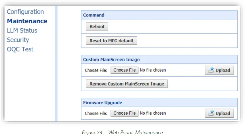
- Soft Reboot
To “soft reboot a unit select the Reboot button - Reset Factory Defaults
To reset a unit’s Factory Defaults, select the Reset to MFG Defaults button. - Change Static Image on Main Screen
To change the static image which is displayed on a unit’s main screen:- Select the Choose File button.
- Navigate to an image which is 800px X 410px.
- Select the Upload button.
- Revert Static Image on Main Screen
To revert the static image which 1s displayed on a unif’s main screen to the default image, select the Remove Custom MainScreen Image buton. - Manual Firmware Upgrade
To manually upgrade the firmware of a unit:- Select the Choose File button.
- Navigate to a firmware file package (tar.gz file).
- Select the Upload button.
- The firmware upgrade process will take several minutes. DO NOT close the window until the firmware upgrade process has been successfully completed.
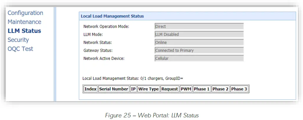
Local Load Management Status (LLM Status)
The local load management status of a unit can be accessed by selecting the LLM Status link on the left pane.
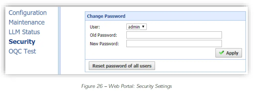
Security Settings
The security settings of a unit can be accessed by selecting the Security link on the left pane.
OQC Test Functionality
The OQC Test functions are reserved for testing purposes only and must not be used for any other purpose.
TROUBLESHOOTING
Troubleshooting Table
| Situation | Screen Displayed | Action |
| Out of Service: Station Disabled | 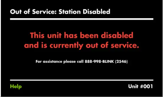 |
|
| Out of Service: Internal Maintenance | 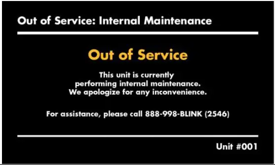 |
|
| Station Unavailable Screen | 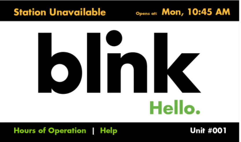 |
|
| Station Availability Notification | 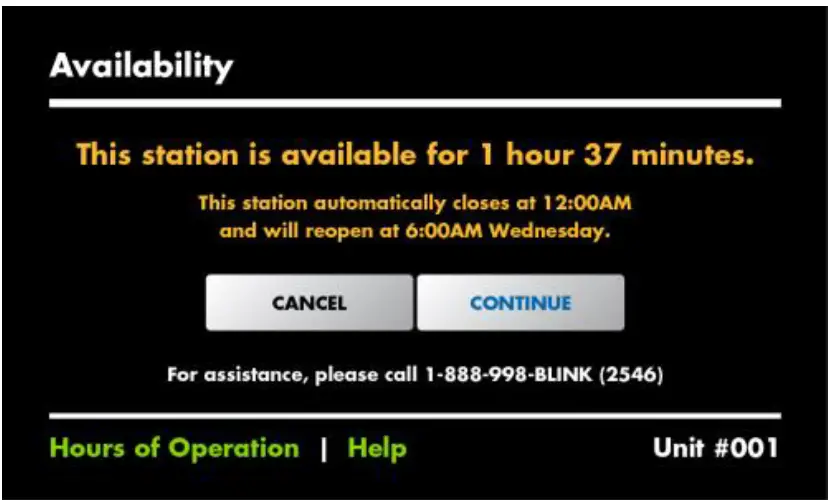 |
|
| Unable to Read Payment Card | 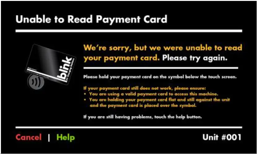 |
|
| Payment Card Declined | 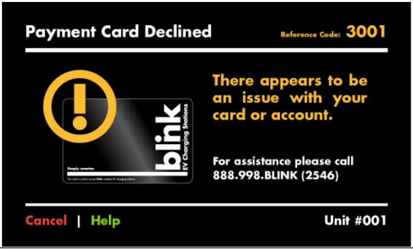 |
|
| Blink Code is not Valid | 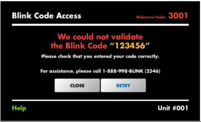 |
|
| Blink Code Access is Unavailable | 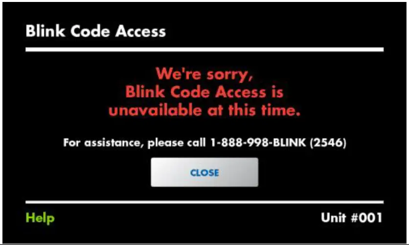 |
|
| Kiosk Only: The Selected Blink Unit is Invalid | 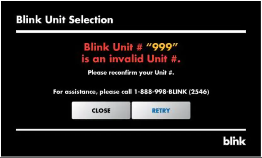 |
|
| Kiosk Only: The Selected Blink Unit is Currently Unavailable | 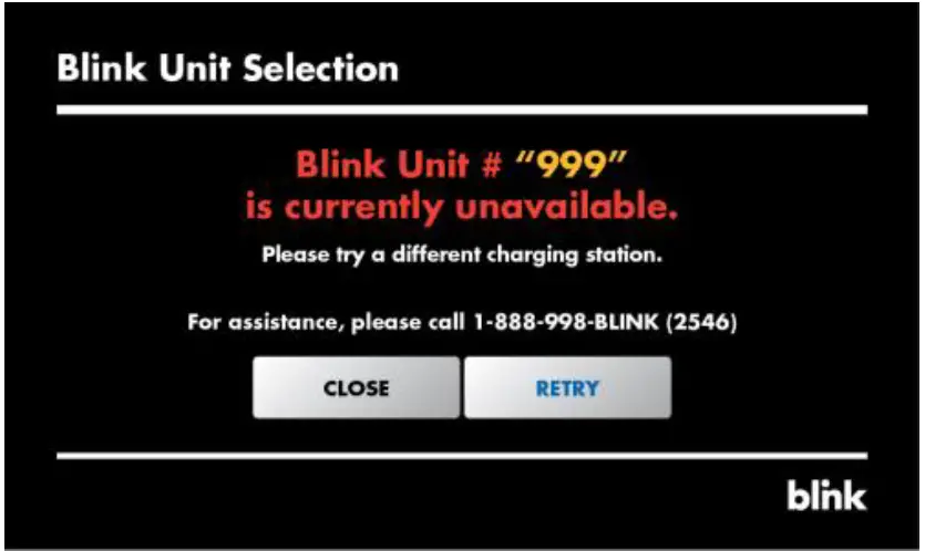 |
|
| Fault with Automatic Reset | 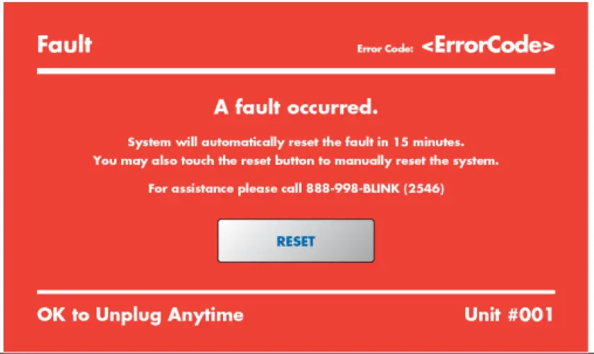 |
|
| Fault with Manual Reset | 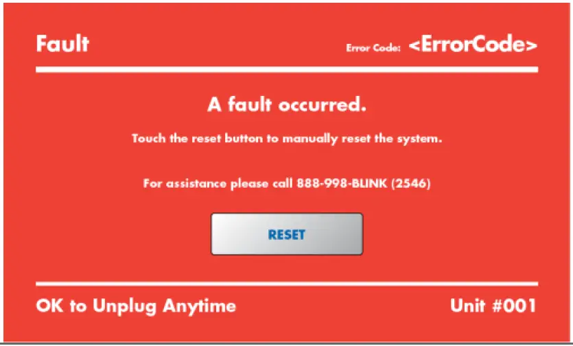 |
|
| Fault with No Reset | 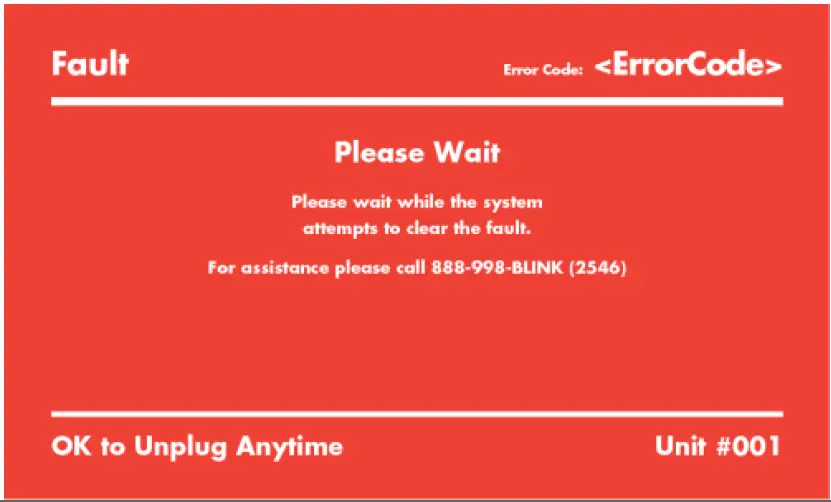 |
|
Automatic Restart Functionality
When a charge session is interrupted due to a temporary error condition, the Blink Product will automatically restart the charge session when the temporary error condition is resolved. The status indicator light will remain flashing RED until the error condition is resolved.
- Temporary error conditions include: Over Current, Over Voltage, Under Voltage, Over Temperature.
- For Over Current (OC) conditions: The charge session will be stopped while the OC condition occurs. After recovery from OC condition for 30 seconds, the Blink Product will automatically restart the charge session (for 3 times).
- When a charge session stopped by the Charge Circuit Interrupting Device (CCID), the Blink Product will attempt to restart the charge session after 15 minutes (for 3 times).
Power Outage Recovery
When power is reapplied after a power outage, the Blink Product will restart the charge session automatically (if the Resume Charge After Reboot setting is On) with a delay ranging from 120 to 720 seconds. The randomized delay is introduced to avoid impacting the utility grid if multiple charging stations are in the same area and attempt to resume their charge sessions simultaneously.
Error Codes
| Error Code | Error Name | Error Description |
| 1000 | No Error | No error to report. |
| 1001 | Ground Failure | Ground fault circuit interrupter has been activated. Same as CCID protection. |
| 1002 | Missing Ground Failure | Failure of missing ground of AC inputs. |
| 1003 | Power Switch Failure | Failure to control power switch. |
| 1004 | Power Meter Failure | Failure to read power meter. |
| 1005 | Reader Failure | Failure with ID tag reader. |
| 1006 | Display Failure | Failure with LCD display or touch panel. |
| 1007 | Cellular Modem Failure | Failure with cellular modem. |
| 1008 | Wi-Fi Module Failure | Failure with Wi-Fi module. |
| 1009 | Reset Failure | Unable to perform a reset. |
| 1010 | High Temperature | Temperature inside charge point is too high. |
| 1011 | Low Temperature | Temperature inside charge point is too low |
| 1012 | Over Voltage | Voltage has increased higher than an acceptable level. |
| 1013 | Under Voltage | Voltage has dropped below an acceptable level. |
| 1014 | Control Pilot Failure | Failure with control pilot circuit |
| 1015 | Clock Failure | Failure with internal clock. |
| 1016 | Self Test Failure | Failure with self-tests. |
| 1017 | Weak Signal | Wireless communication device reports a weak signal. |
| 1018 | Other Error | Other type of error. |
| 2001 | Low Temperature Warning | Low temperature warning. |
| 2002 | High Temperature Warning | High temperature warning. |
| 2003 | Over Voltage Warning | Over voltage warning. |
| 2004 | Under Voltage Warning | Under voltage warning. |
| 2005 | Over Current Warning | Over current warning. |
Table 6 Error Codes
Reference Codes
| Error Code | Error Name | Error Description |
| 3000 | Accepted | Identifier is allowed for charging. |
| 3001 | Blocked | Identifier has been blocked. Not allowed for charging. |
| 3002 | ConcurrentTx | Identifier is already involved in another transaction. |
| 3003 | Expired | Identifier has expired. Not allowed for charging. |
| 3004 | Invalid | Identifier is unknown, including suspended account, invalid RFID, or inactive RFID. Not allowed for charging. |
| 3005 | NoCredit | The identifier is recognized and associated to a user with a membership. However, the balance of this account or credit card has exceeded |
| 3006 | CreditAuthFailed | Failed to authorize user s payment credit, especially for smart credit cards, Apple Pay, and Google Pay. |
Table 7 Reference Codes
GENERAL CARE
The exterior of the Charger is designed to be waterproof and dust proof.
To ensure proper maintenance of the charger, follow these guidelines:
- Despite the water resistance of the enclosure, DO NOT direct streams of water at the unit. Clean the unit with a soft, damp cloth.
- Make sure the charging connector is returned to the holster after a charge session to avoid damage.
- Ensure the power cable is properly stored on the unit after a charge session to avoid damage.
- If the power cable or the charging plug is damaged contact the Blink Network Support Center.
Contact your lighting representative at [email protected]
P: 754.702.2709
Blink IQ 200 Level 2 AC EVSE Instruction Manual 10/9/2019


