![]()
USER MANUAL
LXP HYBRID INVERTER Standard Model:
LXP 3K/3.6K/4K/4.6K/5K/6K Hybrid Parallel Model:
LXP 3K/3.6K/4K/4.6K/5K/6K MG
High Voltage Model:
LXP 4K/5K/6K HB
” Where sun shied Power always-on ,,
![]()
Monitor APP Download
 |  |
| https://play.google.com/store/apps/details?id=com.nfcx.luxinvpower | https://itunes.apple.com/cn/app/luxpowerview/id1415841608?mt=8 |
Safety
1.1 Symbol Explanation
Symbols in This Manual
The general information and safety instruction is highlighted with the following symbols in this manual:
| Notice | |||
| “ Danger indicates a hazardous situation which, if not avoided, will result in death or serious injury. ” | “Warning” indicates a hazardous situation that, if not avoided, could result in death or serious injury. | “ Caution indicates a hazardous situation which, if not avoided, could result in minor or moderate injury.” | “Notice” provides tips that are valuable for the optimal operation of your products. |
Symbols on Inverter Label
Following list shows the meaning of all the safety symbols on inverter type label:
|
|
| Beware of the hot surfaces. The inverter can be hot during operating, avoid contact during operating. |
Danger of high voltage. Danger to life due to the high voltages in the inverter. |
 RCM Mark
 Certification
![]() Risk of electric shock.
Risk of electric shock.![]() Observe enclosed documentation
Observe enclosed documentation![]() Danger of high voltage. Residual voltage in the inverter needs 5min to discharge, wait 5min before operation.
Danger of high voltage. Residual voltage in the inverter needs 5min to discharge, wait 5min before operation.
General Saftey Instructions
The inverter has been designed and tested strictly according to international safety regulations. Read all
safety instructions carefully prior to any work and observe them at all times when working on or with the
inverter. The operator must be qualified personnel and the installation must be capable of relevant
national or international standards or regulations.
Incorrect operation or work may cause:
– injury or death to the operator or a third party; or
– damage to the inverter and other properties belonging to the operator or a third party.
Important Safety Notification.
There are many safety issues that need to be carefully notified before, during, and after the installation, and also in future operation and maintenance, following is important safety notifications to the operator, owner, and user of this product’s inappropriate usage.
![]() DANGER Dangers of High Voltages and Large Current.
DANGER Dangers of High Voltages and Large Current.
- Beware of high PV voltage. Please turn off the DC switch of PV Panel output before and during the installation to avoid electric shock.
- Beware of high grid voltage. Please turn off the AC switch of the grid connection before and during the installation to avoid electric shock.
- Beware of the large current of the battery output. Please turn off the battery module before and during the installation to avoid electric shock.
- Do not open the inverter when it’s working to avoid electric shock and damage from live voltage and current from the system.
- Do not operate the inverter when it’s working, only the LCD and buttons can be touched in limited cases by qualified personnel, other parts of the inverter can be touched when the inverter is under a safe state(e.g. fully shut-down).
- Do not connect or disconnect any connections (PV, battery, grid, communication, etc.) of the inverter when it’s working.
- Make sure the inverter is well-grounded, an operator should make sure itself is well protected by reasonable and professional insulation measurements (e.g. personal protective equipment (PPE)).
- Inspect relevant existing wiring on-site of the installation is under good condition before installation, operation or maintenance.
- Inspect the connections are good between inverter and PV, battery and grid during installation to prevent damage s or injuries caused by bad connections.
![]() WARNING Avoid misoperation and Inappropriate Usage
WARNING Avoid misoperation and Inappropriate Usage
- All the work of this product (system design, installation, operation, setting and configuration, maintenance, etc. must be carried out by qualified personnel as required.
- All connections must be in accordance with local and national regulations and standards.
- Only when permitted by the utility grid, the inverter and system can interconnect with the utility grid.
- All the warning tables or nameplates on the inverter must be clearly visible and must not be removed, covered, or pasted.
- The installation should choose the right position and location as required in this manual with consideration to the safety of users in future operations.
- Please keep the children away from touching or misoperation the inverter and relevant system.
- Beware of burning hurt, the inverter and some parts of the system could be hot when working, please do not touch the inverter surface or most of the parts when they are working. During inverter working states, only the LCD and buttons could be touched.
![]() CAUTION
CAUTION
Only qualified personnel can change the inverter settings.
There might be possible damage to the health as a result of the effects of radiation, do not stay closer than 20cm to the inverter for a long time.
NOTICE
Please carefully read this manual before any work is carried out on this inverter, after the installation, please keep this manual carefully stored and easy to access at any time.
The qualified person should have had training in the installation and commissioning of the electrical system as well as dealing with hazards, also they should have the knowledge of the manual and other related documents. As the installer or operator, they are required to be familiar with local regulations and directives.
Brief Introduction
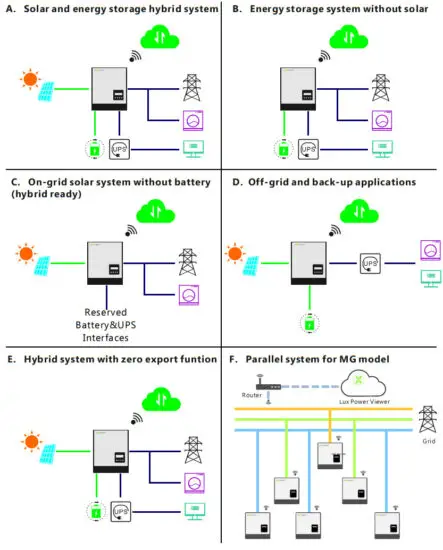
2.1 System Solution
This product and the relevant system are suitable for the following system applications (system diagram):
Installation
3.1 Packaging List & Storing
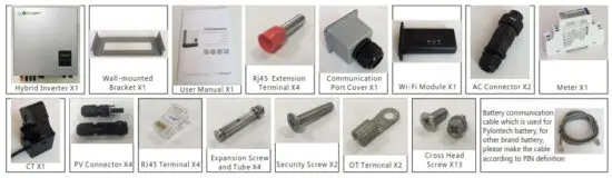
Packaging List
When the packaging is unpacked, the inner components should be the same as described in below packaging list.
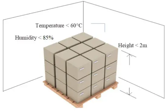
Storing the Inverter
The inverter must be stored appropriately if not installed immediately, refer to the below figure.
![]() CAUTION
CAUTION
a) The inverter and its components must be stored in its original packaging.
b) The storage temperature should be within -25~60 and humidity within 0~85%.
c) The packing should be upright and the maximum number of stacked layers is 6.
d) Do not expose the inverter and its packaging to direct sunshine, and raindrops and keep away from corrosion.
3.2 Select Location
The LXP hybrid inverters are designed as IP65 devices with the capability to be installed in both outdoor and indoor conditions. However, selecting an optimal installation location is highly recommended to increase the safety, performance, and lifespan of the inverter. Please note the installation should not be accessible to children for safety considerations.
Suggestions and Requirements
a) The wall for mounting should be strong enough to bear the weight of the inverter.
b) The ambient temperature is required to be within -25°C ~ 60°C.
c) To ensure the heat dispassion efficiency and inverter lifespan, do not install the inverter enclosed.
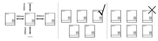
d) The structure of the wall where the inverter is mounted should not be flammable, or make sure the inverter is not surrounded by flammable or corrosion materials and is away from the gas.
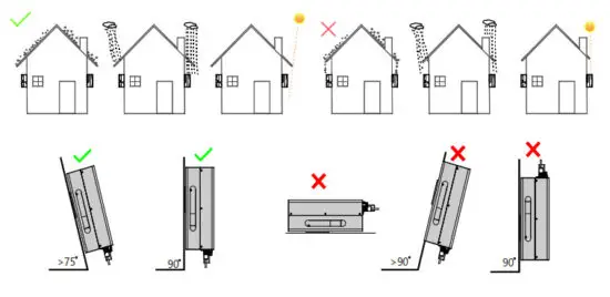
e) Never install the inverter exposed to direct sunshine, rain, and snow. Please refer to the below figure and select a well-shaded place or install a shell to protect the inverter from direct sunshine, rain, snow, etc.
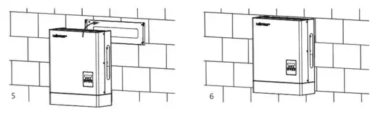
3.3 Install the Inverter
The inverter is wall-mounted installed, steps show below:
Step1. Use the wall-mounting bracket as the template to mark the position of the 4 holes, then drill 8 mm holes and make sure the depth of the holes is deeper than 50mm.
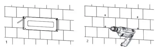
Step2. Install the expansion tubes into the holes and tighten them, then use the expansion screws (packaged together with the expansion tubes) to install and fix the wall-mounting bracket on the wall.
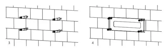
Step3. Install the inverter on the wall-mounting bracket and lock the inverter using the security screws.
3.4 Connection
3.4.1 Connection Overview
The system connection diagram is as below:
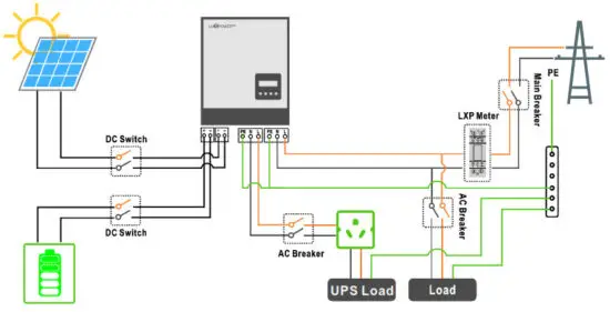
Please prepare the breakers before connection, breakers selection recommendation for both DC and AC
Hybrid | LXP 3K/3.6K/4K (MG) | LSP 4.6K/5K (MG) | LXP 6K (MG) | LXP 4K HB (MG) | LXP 5K HB (MG) | LXP 6K HB (MG) |
| DC Breaker selection(2 poles) | 100A/100V | 100A/100V | 50A/500V | 50A/500V | 50A/500V | 50A/500V |
| AC Breaker selection(2 poles) | 40A | 50A | 50A | 50A | 50A | 50A |
| UPS Breaker selection(2 poles) | 40A | 40A | 50A | 50A | 50A | 50A |
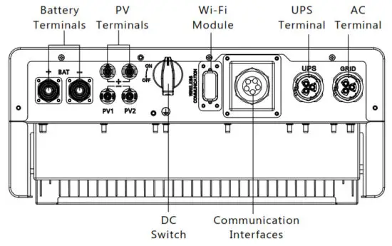
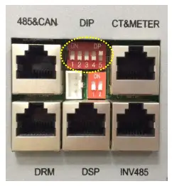
Connection Terminals and Interfaces Overview
3.4.2 PV Connection
The PV connection of the LXP hybrid inverter is the same as the traditional on-grid solar inverter (string inverter).
Notice
- Before connecting the PV, please use the multi-meter to measure the PV array voltage to verify if the PV array is working normally, if not, please fix the PV array to a normal working state before connection
- When your PV panel ambient temperature could possibly be lower than 0 ℃, then please check the PV array voltage up the ceiling and if you are not sure please ask your system panel provider for further assistance. As when the temperature is extremely low the PV panel voltage will increase by a certain percentage.
Cable Requirement:
| Cross-section | Cable Diameter | Minimum Voltage |
| 3 – 6 mm | 2-2.6mm | 600V |
Step1: Turn off or disconnect the PV switch (DC switch). Then keep this switch always open during the connection.
Step 2: Assemble the PV connector

a) Strip 6~8mm insulation from the cable end.
b) Assemble the cable ends to crimp contacts.
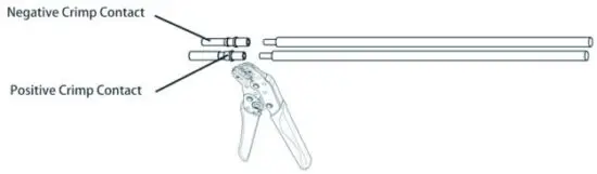
c) Lead the cable through the cable gland, then insert it into the corresponding insulator until it snaps into place, then tighten the cable gland.
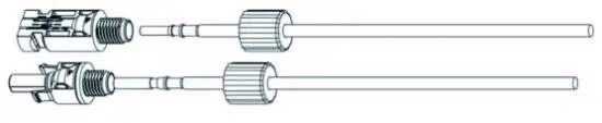
When verified the PV connector is tightened, align the 2 half connectors and mate them together by hands until ‘click’ is felt or heard.
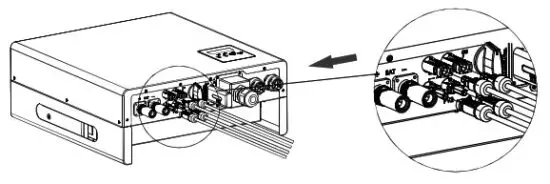
3.4.3 Battery Connection
This part in this manual only describes the battery connection on the inverter side, should you need more detailed information regarding the battery connection on the battery side please refer to the manual of the battery you are using.
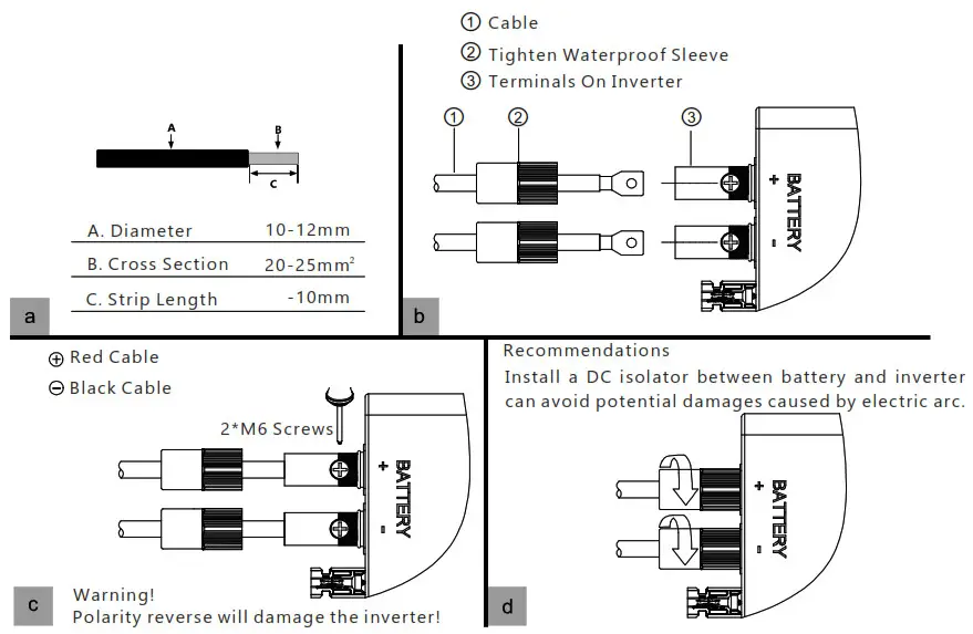
Step 1: Assemble the terminal.battery connection.
NOTICE
For the first time power on, please turn on the batte ry after the LCD show “Run without Bat”, otherwise it may shorten the lifetime of the inverter.
For lead-acid batteries temperature sensor, please refer to Page29 “Cable Connection” figure.
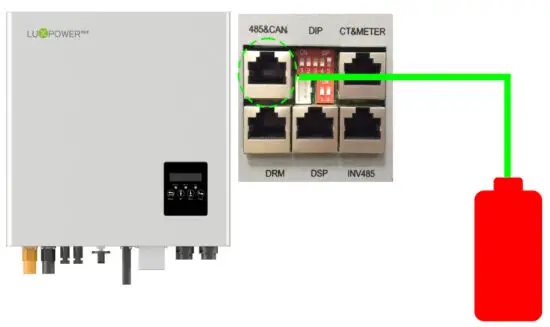
Battery Communication Connection
If the battery type is lithium-ion or ternary battery which needs communication between the inverter and battery management system (BMS), the communication connection must be installed.
RJ45 Terminal Configuration of Battery Communication
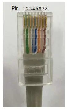
| Pin | Function Description |
| 1 | BAT 485 B |
| 2 | BAT 485 A |
| 3 | BAT CAN L |
| 4 | BAT CAN H |
| 5 | NC |
| 6 | BAT NTC |
| 7 | BAT Wake UP |
| 8 | GND-S |
Make the RJ45 terminal based on the above introduction of each Pin definition, you could either make an RS485 connector or CAN connector based on the best support connection way of your battery packs. For the Lead-acid battery temperature sensor, please connect the signal to Pin6 and Pin8, the other pins are not connected.(External temperature sensor is needed, the sensor is a 15KΩ thermistor for typical, or consult Luxpowertek)
NOTICE
For Li-ion battery
- If works with a lithium battery, please make sure it is compatible with the Lux units. Now Lux Power inverter is compatible with Pylontech, Dryness, Aoboet, Weco, Murata, and Merit 48V batteries.
- After the battery power cable and communication cable connection, users need to choose the battery brand by LCD
- The battery communication cable inside the Luxpower carton box is used for the Pylontech battery, if you are using a Pylontech battery, you can use the cable directly. Please note there is a label ‘BAT’ (need to plug into battery side) attached with the cable, do not plug the battery side terminal to the inverter side
- If you install more than 8pcs Pylontech batteries, you need a hub for the battery.
- Please remember to connect the Master battery to the inverter if you have a battery group, and set the Master battery for the battery group.(Please contact battery manufacturer for battery group setup).
For Lead-acid battery
- The lead-acid battery temperature sensor cable is optional, if required, please request the temperature sensor cable from your supplier.
- There are three stages for lead-acid battery charge. For the charge part, please set CV voltage e andfloating voltage. For the discharge part, please set the discharge cut off voltage for on-grid and off-grid
The connection between inverter and battery
3.4.4 Grid Connection
Cable Requirements:
| Cross-section | Diameter |
| 4 – 6 mm2 | 2 mm – 2.6 mm |
Step 1: Assemble the AC connector.
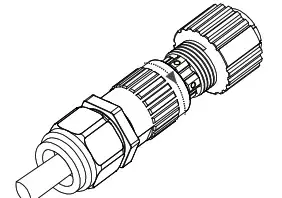
| AC Connector Structure Overview | a) Lead the AC cable through the cable gland, seal ring, and threaded sleeve, fully insert the conductors to corresponding terminals on the connection terminal and tighten the screws. |
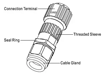 | 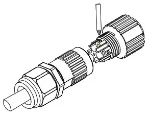 |
| b) Refer to the below figure and confirm the AC cables are correctly connected. The difference between the AC connector and UPS connector is that the AC connector has a “Grid” mark on it and UPS does not | c) Assemble the GRID connector and make sure that the rib of the terminal block and the groove on the housing engage perfectly until a ‘click’ is heard or felt. |
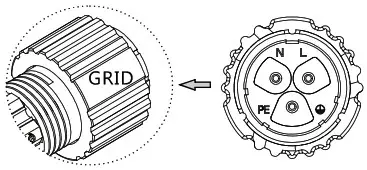 |  |
Step 2: Install the AC connector
a) Align the GRID connector and AC terminal and mate them together by hand until a ‘click’ is heard or felt.
b) An AC breaker (AC switch) should be installed between the inverter and the grid, confirm the AC breaker is working normally before connecting the AC cable from the inverter to the AC breaker. Turn off the AC breaker and keep it open.
c) Connect the PE conductor to the grounding electrode, and connect N and L conductors to AC breakers.
d) Connect the AC breakers to the AC grid.
e) You must install a separate single-phase circuit-breaker or other load disconnection unit for each inverter in order to ensure that the inverter can be safely disconnected under load.
NOTICE
The inverter has the function of detecting residual current and protecting the inverter against the residual current. If your inverter has to equip an AC breaker that has the function of detecting residual current, you must choose an AC breaker with a rating residual current of more than 300mA.
3.4.5 UPS/Back-up Connection
Cable requirements
| Cross-section | Diameter |
| 4 – 6 mm2 | 2 mm – 2.6 mm |
Step 1: Assemble and install the UPS connector process is the same as AC connectors which show in Chapter 5.4 Grid Connection (Step 1 and Step 2). Finish the UPS connector assembling and installation first of all.
Step2: UPS warning
There are 2 different UPS wiring modes in accordance with different local or national rules, standards or regulations. Please choose the suitable wiring mode according to the local requirements.
Mode A: Neutral line of alternative supply must not be isolated or switched. The connection diagram of UPS Connection Mode A is shown in the below figure.
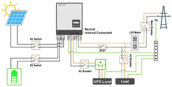
NOTICE
Backup loads neutral and grid neutral are connected internally inside the inverter, so the installer does not need to connect them outside. The power of the backup load should be lower than 5kW.
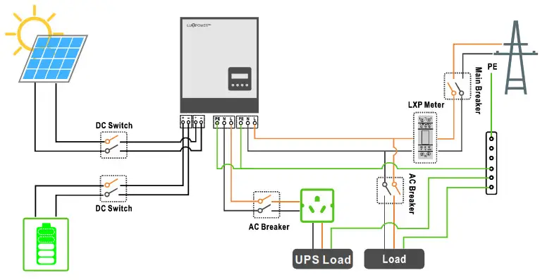
Mode B: Neutral lines of alternative supply can be isolated or switched.
The connection diagram of UPS Connection Mode B is shown below figure.
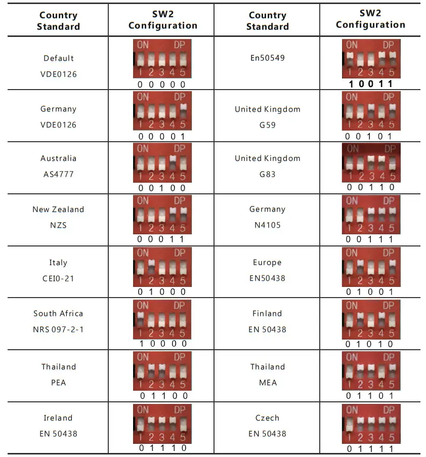
3.4.7.2 Safety Standard Configuration – SW2
By configuring the DIP switch the inverter could comply with different safety requirements of various areas.
Sw2 Safety Standard Configuration Switch Overview
Note: The DIP switch is composed of five-digit binary number PINs. Each PIN has two statuses when set upward to“ON”, its value turns to“1” when set downward, its value turns to “0”.
Safety Standard Configuration Guidance
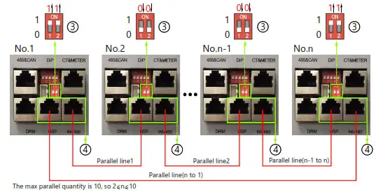
3.4.7.3Blancing Resistor Configuration
By configuring the SW1 balancing resistor configuration switch, you could configure the balancing resistors of parallel CAN communication. This Function is used for multiple inverters paralleling operations.
Please turn on the DIP in the first and last inverter in the inverter loop. For more info, please check the parallel connection part.
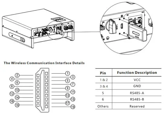
3.4.7.4 Wireless Communication Module Connection
3.4.8 Grounding
The second protective earth (PE) terminal is equipped at the side of the inverter. Be sure to connect this PE terminal to the PE bar for reliable grounding.
Cable Requirements
3-6mm² copper cable or 10-16mm² aluminum cable.
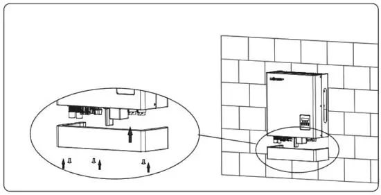
NOTICE
Install the Protective Shell
When you finish all of the above chapters of connections, please don’t forget to install the protective shell back to the inverter. This step can be carried out either after finished grounding or c Tommi SSI one of the systems.
Operation Guide
4.1 Operation Mode
Users can have different settings to satisfy their demands, the working modes are as below:
Operation | Explanation | Related Settings | Application Notes |
| Self-usage (Default mode) | The priority of the PV energy will be Load > battery > grid, which means the energy generated by PV will be mainly used by local loads, and the rest will be stored in the battery, and excessive power will be feedback into the grid. | Effective when charge priority and force-time charge/discharge are disable | increase the self-consumption rate and reduce the energy bill significantly |
| Charge priority | The priority of the PV energy will be battery >Load >grid, which means the energy generated by PV will be used to charge the battery first, and then used by local loads, excessive power will be feedback into the grid. | Charge Priority and related time, SOC | When the load shedding always happens, users need to charge the battery first |
| Force time | Users can set the charging and discharging time and priority of energy use under Force Time Use mode. This is also used to flexibly make use of your system by customized settings by the users. | Force charge/discharge enable and disable, and related time SOC | This mode suits situations where the price difference of energy is big under Time of Use (To U) |
| Micro Grid mode(Genset) | When used in the pure off-grid application, users may connect the Gen-set the output to grid input, when battery SOC is low. The inverter will use the generator to take the load and charge the battery. | Microgrid enable /disable | The area where is no grid and there is a utility |
| Off-grid mode | The inverter will switch to off-grid mode automatically when there is no grid. | UPS enables | The area where is no grid |
4.2 LCD operation and settings
4.2.1 LCD Menu Structure Overview
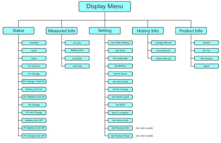
4.2.2 Status and Parameter show in LCD
a. Standby
The inverter is waiting for sufficient DC voltage from the PV or battery. It occurs when the sunlight is not sufficient to make the inverter work and battery SOC is low.
b. Fault
A fault occurred with the inverter or system. The inverter will stop working unless the fault or error is fixed.
For detailed information and troubleshooting please refer to Chapter 8. Troubleshooting & Maintenance.
C. Flash
When upgrading the firmware of the inverter, the inverter will work at flash status.
There are 2 ways to upgrade the firmware of the inverter:
– Remote upgrading based on the remotely connected server through the wireless communication module.
– Locally upgrading through RS485 communication connection.
d) PV Grid On
The inverter is working normally on-grid, and all the power generated by PV will export or feed in via the AC grid connection to your general loads and the grid.
e) PV Charge
The inverter is working normally, the power generated by PV is within a range that all the PV power is used to charge the battery, while there is no excessive power rested to output from neither the AC Grid connection nor UPS connection.
f) PV Charge + Grid On
The inverter is working normally on-grid, the power generated by PV is sufficient and within a range in which PV power is used to charge the battery and there is still excessive PV power rested to export or feed in via the AC grid connection. Under this inverter working status, your general loads will either consume the power from PV or use power from the grid or at the same time from the two sources, the detailed situation is based on the PV power output range and your general load’s power demands differences.
g) Battery Grid On
The inverter is working on the grid with no PV power input, and there is sufficient energy stored in the battery, the inverter is discharging the battery and exporting the power via AC grid connection to your system.
h) PV+Battery Grid On
The inverter is working normally on-grid with limited PV power input and the battery energy is sufficient, at this inverter working status the limited PV power is used together with the battery discharging power to export or feed in via the AC grid connection.
I) AC Charge
The inverter is working normally on-grid with no PV input power, and is using the AC power from the grid to charge the battery as configured previously (the function should be enabled firstly as Chapter Inverter Settings – h) AC Charge Settings described).
j) PV+AC Charge
The inverter is working normally on-grid with limited PV input power, and the batter SOC is not sufficient, if at this time the inverter is configured to charge the battery with both PV power and AC grid power, then the inverter will run in this status.
k) Battery Grid Off
The inverter is working normally off-grid with no PV input power, and the battery SOC is sufficient. When the inverter works at this status, the battery is discharging to output power via the UPS connection.
l) PV Battery Grid Off
The inverter is working normally off-grid with limited PV input power, and the battery SOC is sufficient.
When the inverter works at this status, the battery is discharging together with the PV power to output via the UPS connection.
m) PV Charge Grid Off
The inverter is working normally off-grid with sufficient PV input power, and the battery SOC is insufficient. Wen inverter works at this status, the inverter is charging the battery using PV power and there is excessive power rested to output via the UPS connection.
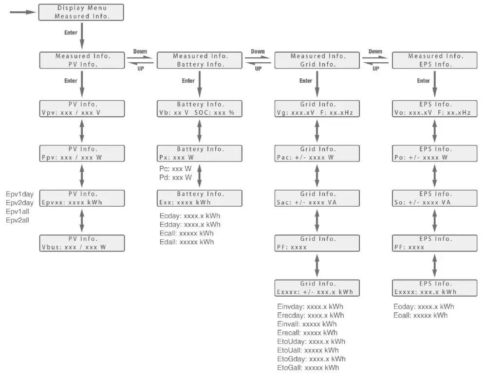
Parameter Explanation of LCD Displays
Parameters of Power:
| Ppv: PV input power | Pac: active power of AC output |
| Sac: apparent power of AC output | Po: active power of UPS |
| So: The apparent power of UPS | Pc: Charging power |
| Pd: discharging power | PhotoGrid: active power of exporting / feed-in to grid |
Parameters of Voltage and Frequency etc.
| Vb: battery voltage | Vo: UPS voltage |
| Vbus: voltage of DC bus | Vg: grid voltage |
| F: frequency | SOC: state of charge |
Parameters of Energy:
| Einvday: energy output via AC output today | Einvall: total energy output via AC output |
| Ecday: charged energy today | Ecall: total charged energy |
| Edday: discharged energy today | Edall: total discharged energy |
| Eoday: UPS output energy today | Eoall: total UPS output energy |
| Epv1day: energy generated today of PV array 1 | Epv2day: energy generated today of PV array 2 |
| Epv1all: total energy generated of PV array 1 | Epv2all: total energy generated of PV array 2 |
| Erecday: AC charge energy of today | Erecall: total AC charge energy |
| EtoUday: energy consumed by loads today | EtoUall: total energy consumed by loads |
| EtoGday: feed-in energy today | EtoGall: total feed-in energy |
4.2.3 LCD Settings
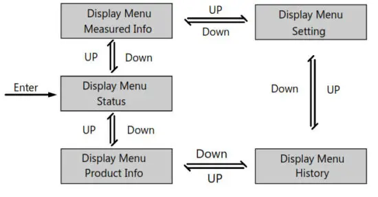
4.2.3.1 Information Searching
Refer to the below flow chart which shows the information option interfaces and interconnection.
The operator can search for target information by following the below directions.
a. Enter into Display Manu Interface
Touch the Return button to enter the Display Menu interface, search and select corresponding information options using the Up and Down button, relevant information will be immediately displayed on the LCD screen after touching Enter button to confirm the selection.
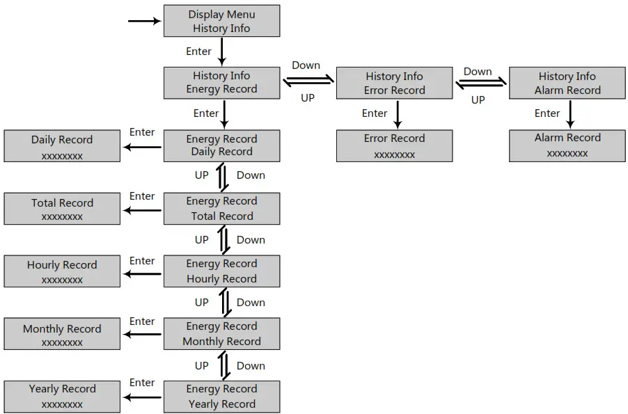
B. Search History Information
In the Display Menu interface, select the History menu and touch Enter button to enter the History menu interface and use the Up and Down button to select the relevant display menu, and touch Enter button to view detailed historical information.
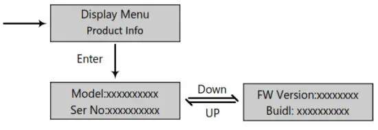
C. Search Product Information
In the Display Menu interface, select Product Info. menu and touch Enter button to enter the Product Info. the menu interfaces to view detailed product information.
d. Search Measured information
In the Display Menu interface, select Measured Info. menu and touch Enter button to enter in the Measured Info. the menu interfaces to view detailed running information of the system, such as PV, battery, grid, and UPS data.
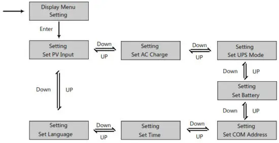
4.2.3.2 Settings Guidance
a) Enter Into Setting Interface
Touch the Return button to enter into the Display Menu interface, search and select the Setting menu using the UP and Down button, and then touch Enter button to confirm and enter into the inverter setting interface.
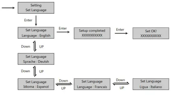
b) Language Setting
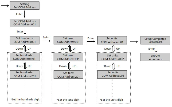
c) Communication Address setting
Notice that the setting range of the RS485 communication address is from 000 to 255, and it’s set to be 001 by default when manufactured.
Operating Guidance: by touching Enter button to select the numerical digits of the COM address – hundreds, tens, and units, and use the UP and Down button to set the number of selected numerical digits.
d) Battery Setting
In the Setting interface, search and select the Set Battery menu and touch Enter button to confirm and enter into the battery setting interface. Set the battery parameters and configuration follow the direction in the below flow chart. Notice that the LXP Hybrid series energy storage inverter supports Lithium-ion and Lead-Acid type batteries. Operating Guidance: by touching Enter button to select the options and use the Up and Down button to set the parameter or number of selected options.
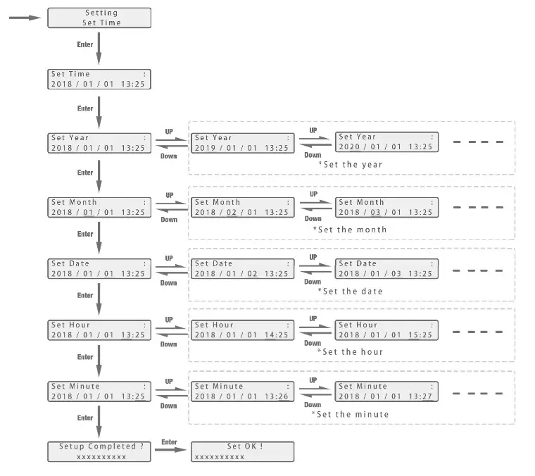
e) Time Setting
In the Setting interface, search and select the Set Time menu then enter into the time setting interface. Follow the direction in the below flow chart to set the time parameters.
Operating Guidance: by touching Enter button to select the numerical digits of the time – year, month, date, hour, and minute, and use the Up and Down button to set the number of selected numerical digits.
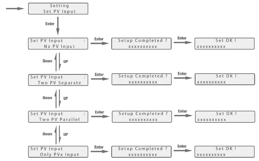
f) PV Input Setting
Operating Guidance: by touching the Up and Down buttons to select the parameter of the PV input. Notice that the PV input parameters must be set in accordance to actually the configuration of the PV system. The parameter is set to Two PV separate by default.
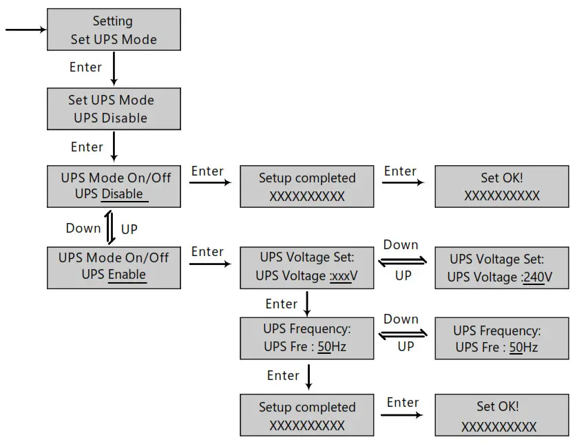
g) UPS Setting
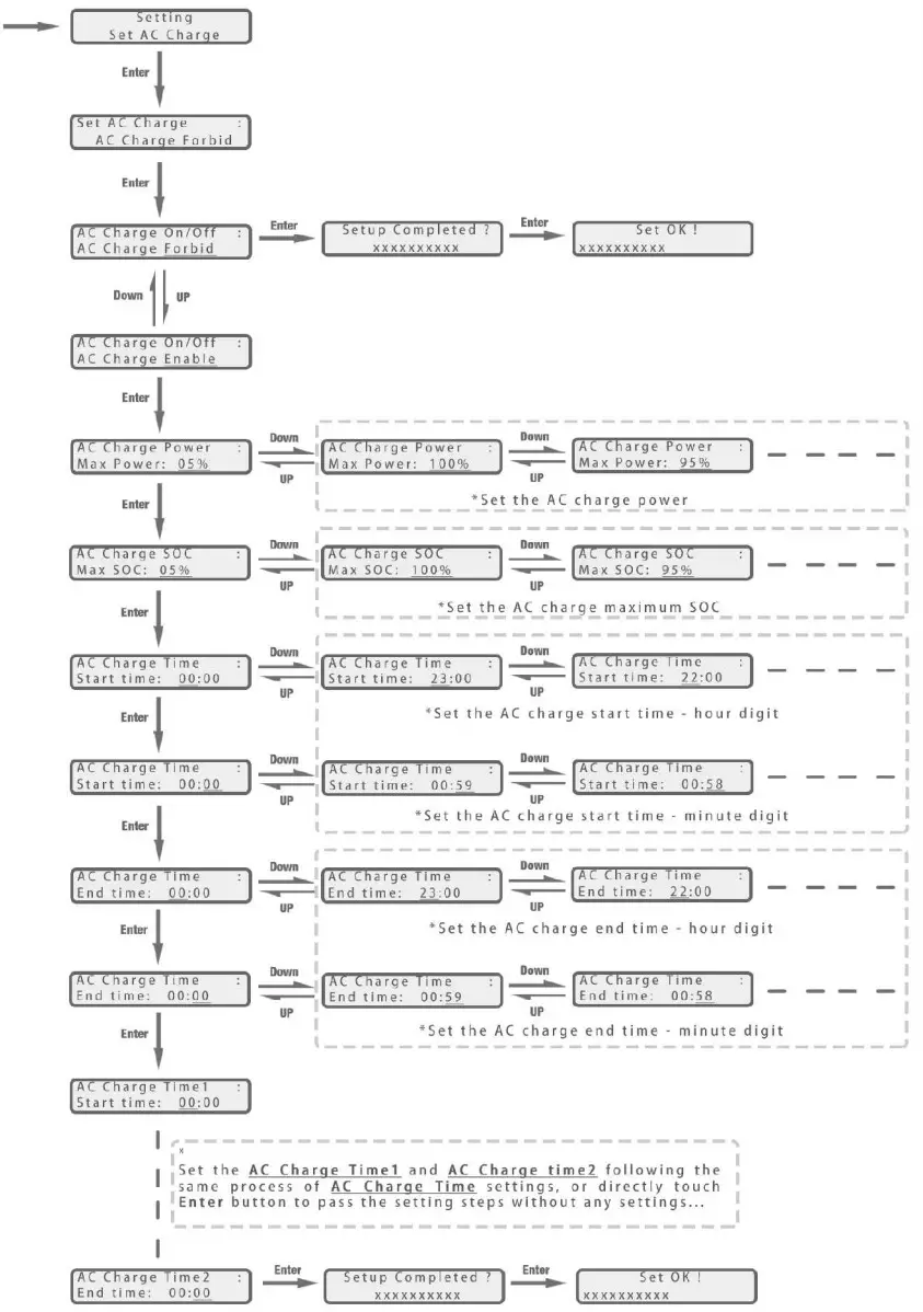
h)AC Charging setting
In the Setting interface, search and select the Set AC Charge menu and enter into the AC charge setting interface. Follow the directions in below flow charge to enable or disable the AC charge function, if enabled then configure relevant parameters.
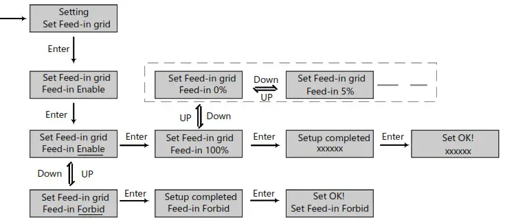
I) Feed-in grill setting
Since in some countries, users can not feed energy into the grid, so they are able to disable the energy export function in the LCD or set the power percent which can feed into the grid.
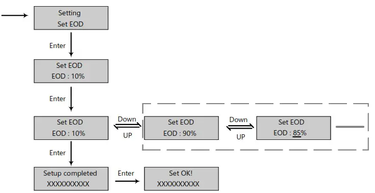
J) EOD Setting
Users are able to set the end of discharge (stop discharging) battery le vel when there is a grid. This setting is important for some areas that always have load sheddings.
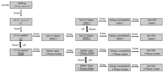
K) CT or Metar setting
Since the inverter supports the connection of both CT clamp and meter, users can select if the system is connecting a meter or a CT clamp and the n chooses the CT clamp ratio when connecting a CT clamp.
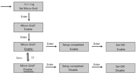
I) Micro-Grid Setting
When connecting the generator to the inverter AC terminal, users need to enable the microgrid function so the inverter will use the generator to charge the battery and will not export any power by the AC terminal.
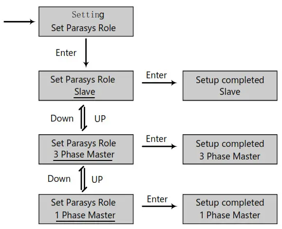
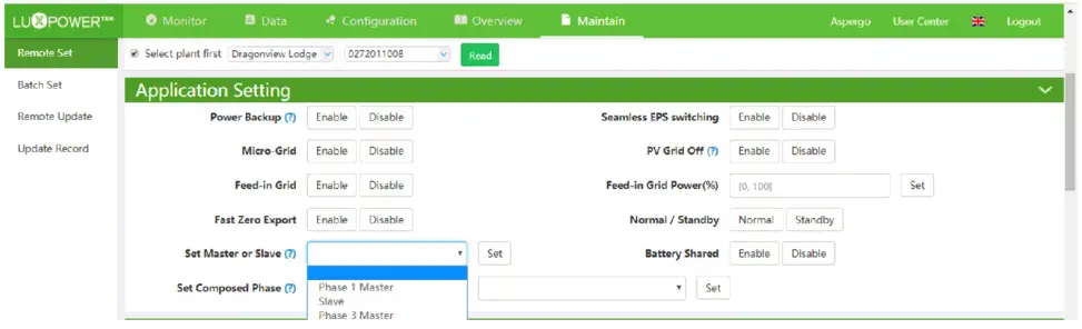
m) Chose master or slave for a parallel system
For a parallel system, users need to set one inverter to master and others to slave. If the system is a single-phase, then users need to choose 1 phase master, if the system is three-phase, then users need to choose a 3 phase master.
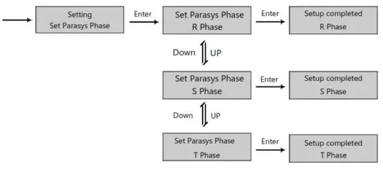
n) Parasys phase setting
For a parallel system, the inverter is able to detect the phase auto if there is three-phase grid input. If the application is a pure off-grid three-phase application, users need to set the phase output for each inverter. For the master, it is considered the phase.
4.3 Monitor System
Users can use wifi dongle/WLAN dongle/4G dongle(Available from 2021 March for some countries) to monitor the energy storage system, The monitor website is: server.luxpowertek.com
The APP is also available in the google play and apple APP stores (Scan two code bars to download the APP).
Please download the introduction of guidance by the website: https://www.luxpowertek.com/download/
Document Reference:
- Quick guidance for setting a password for wifi module the paper is also available in the wifi box
- Wifi Quick Guidance, and Monitor system setup for Distributors Monitor system setup for end users Monitor system registration wifi password setting and wifi local monitor and setting,
- Lux_Monitor_UI_Introduction. Introduction of monitor interface
- WebsiteSettingGuidance. Introduction of website settings for hybrid inverter
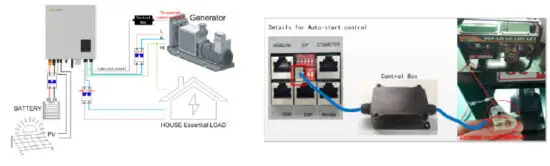
4.4 Work with Gen-set
All lux units can work with a generator.
Users can connect the generator output to the inverter Grid terminal. If you have both grid and generator as AC input, we need an external ATS to switch between grid and generator.
Please purchase an external control box to remote turn on/off the generator(which supports the dry contact function).
The generator will be automatically started when battery voltage is lower than the cut-off value or there is a charge request from BMS. When voltage is higher than the AC charge setting value, it will stop the generator
You should enable the ‘Micro-grid’ function via the APP or Web page while you connect the generator to the
Lux unit. The battery will get charged when the generator is turned on, and the generator is bypassed to take all loads in AC and UPS terminal.
4.5 Parallel system setup guidance
Please note that the parallel model is different from the standard model, if users need to connect the UPS together, they need to buy a parallel model from distributors.
For parallel system setup,
Step1. Cable connection: the system connection for single-phase paralleling is as below: the system connection for three-phase paralleling is as below:
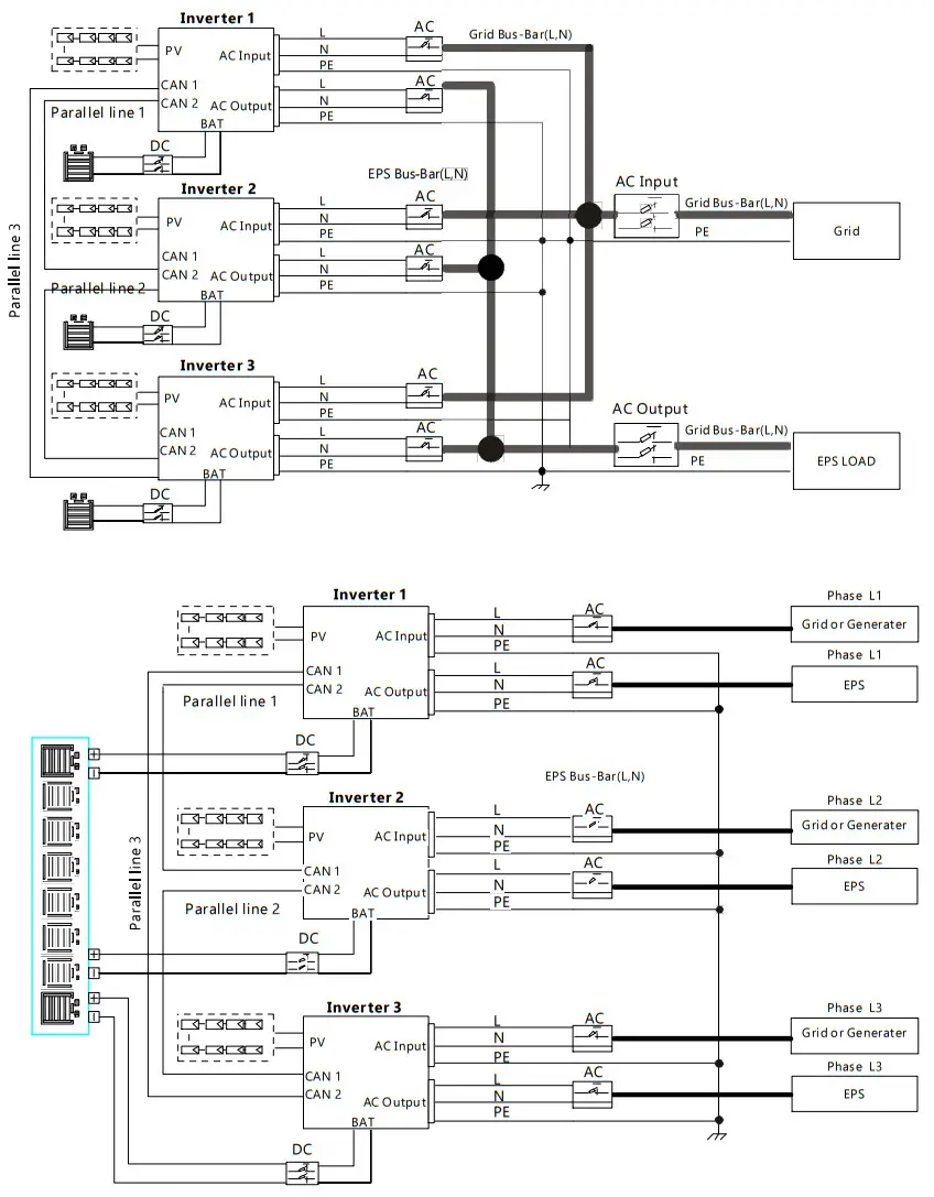
Please put the CAN communication PIN on status for the first and the end inverter
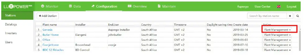
Step2. Setup the monitor for the system, and add all catalogs in one station. Users can log in the visit the monitor system, Configuration->station->Plant Management-> add datalog to add the data logs.
Step3. Setup Master and Slave for Parallel system. There should be only one master in the system. Set one inverter as master and the others as slave
Step4. Enable share battery for the system if the system share one battery bank, otherwise disable the shared battery function.
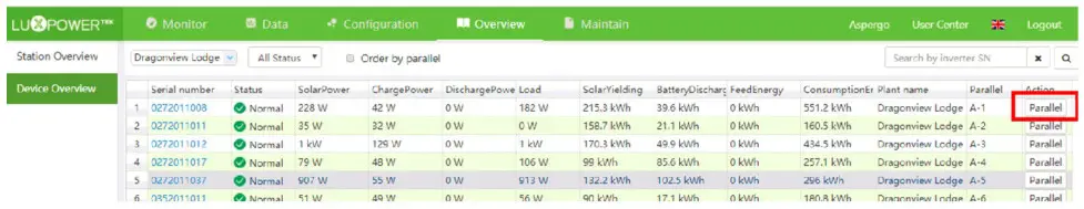
Step5. Set the system as a parallel group in the monitor system.
For more detailed guidance for the paralleling system, please visit And download the guidance https://www.luxpowertek.com/download/
Startup and shut down the inverter
5.1 start up the inverter
Step1. Turn on the battery breaker, then turn on the “EPS Output” switch and check if the inverter works in battery back-up mode.
Step2. Make sure the PV voltage of the strings is higher than 120V, and check if the inverter works in PV charge or PV back-up mode.
Step3. Make sure step1and 2 above work properly before turning the grid power or generator, and check if the inverter can go to bypass mode and on-grid mode normally.
5.2 Shut down the inverter
Danger: Do not disconnect the battery, PV, and AC input power under load.
If there is an emergency issue, and you have to shut down the inverter, please follow the steps as below,
Step1. Cut off AC input breaker of inverter side
Step2. Cut off the breaker of the load side
Step3. Cut off the PV breaker and then cut off the battery, and wait for the LCD to go off.
Step4. Turn off the “Power” switch on the inverter if needed.
Troubleshooting & Maintenance
6.1 Troubleshooting
When faults and errors occurred, please deal with these problems following the below procedures and requirements.
6.1.1 Introduction to LED Displays
| LED | Display | Description | Suggestion |
| Green LED | Long light | Working normally | |
| Flashing | Firmware upgrading | Wait till upgrading complete | |
| Yellow LED | Long light | Warning, inverter working | Need troubleshooting |
| Red LED | Long light | Fault, inverter stop work | Need troubleshooting |
6.1.2 Maintenance
Every segment of the system needs to be checked monthly/quarterly/yearly according to the detailed requirements of each segment.
Inverter Maintenance
a) Check the inverter every 6 months or 1 year to verify if there are damages to cables, accessories, terminals, and the inverter itself.
b) Check the inverter every 6 months to verify if the operating parameter is normal and if there is no abnormal heating or noise from the inverter.
c) Check the inverter every 6 months to confirm there is nothing that covers the inverter heat sink, if there is, shut down the inverter and clear the heat sink.
Battery Maintenance
As per different types of batteries, the original manufacturer’s requirements on maintenance, when you carried out these works on batteries, please make sure to fully shut down the inverter for safety considerations.
6.1.3 Troubleshooting Based On LCD Displays
Once there are any warnings or faults occurred, the LED and LCD will display information to remind the operator, and the LCD will display a relevant error code and a short description.
Code | Description | LCD Display | Troubleshooting |
| £000 | Internal communication fault 1 | E000 | Restart the inverter, if the error still exists, please contact us |
| E001 | Model fault 1 | E001 | Check the parallel CAN cables between inverters, and balance resistor is in the right place |
| £008 | Parallel CAN fault | E008 | Reset the model, check if the safety of the standard switch is in the right place |
| E009 | Master loss | E009 | 1. Check the parallel CAN cables between master to slaves. and the balance resistor is in the right place 2. Check if the parallel system lacks a master inverter, and reconfigure a master. |
| E010 | Multiple masters | E010 | 1. Check if the parallel system has two masters at less. 2. Only allow one master, to reconfigure the others into slaves. |
| E011 | Parallel AC inconsistent | E011 | Check the AC connection between parallel inverters |
| E012 | UPS short circuit | E012 | 1. Check UPS 1_, N connection 2. Disconnect the UPS connector, if the error still exists, contact us. |
| E013 | UPS power reversed | E013 | Restart the inverter, if the error still exists, contact us. |
| E015 | Parallel phase abnormal | E015 | Check the AC connection between the triphase parallel system |
| E016 | Relay fault | E016 | Restart the inverter, if the error still exists, please contact us. |
| E017 | Internal communication fault 2 | E017 | Restart the inverter, if the error still exists, please contact us |
| E018 | Internal communication fault 3 | E018 | Restart the inverter, if the error still exists, please contact us |
| E019 | Bus voltage high | E019 | Wait for the inverter automatically restart complete, if this error repeats several times, please contact us |
| E020 | UPS connection fault | E020 | Check UPS and AC connections |
| E021 | PV voltage high | E021 | Check PV input connection and If PV voltage is in range |
| E022 | Overcurrent | E022 | Restart the inverter, if the error still exists, please contact us |
| E023 | Neutral fault | E023 | Check neutral connection |
| E024 | Both PV short circuit | E024 | Disconnect both PV connections, if the error still exists, contact us |
| E025 | Temperature over range | E025 | Check NTC Connection |
| E026 | Internal fault | E026 | Restart the inverter, if the error still exists, please contact us |
| E027 | Sampling inconsistent between main and slave CPU | E027 | Restart the inverter, if the error still exists, please contact us |
| E031 | Internal communication fault 4 | E031 | Restart the inverter, if the error still exists, please contact us |
| W000 | Communication failure with the battery | Bat Com Fault | Check if the communication cable is right and have chosen the right battery brand, if the warning still exists, contact us |
| W003 | Communication failure with meter | Meter Com Fault | Fix the communication cable, if the warning still exists, contact us |
| W004 | Battery failure | Battery failure | Restart the battery, if the warning still exists, please contact us and the battery manufacture |
| W005 | Auto Test failure | Auto Test failure | Restart the inverter, if the warning still exists, please contact us |
| W016 | No AC connection | No AC Connection | Check AC connection |
| W017 | AC voltage out of range | AC V Outrange | Check AC grid voltage |
| W018 | AC frequency out of range | AC F Outrange | Check AC grid frequency |
| W020 | PV isolation low | PV Isolation low | Restart the inverter, if the error still exist, please contact us |
| W021 | Leakage current high | Leakage I high | Restart the inverter, if the error still exists, please contact us |
| W022 | DC injection high | DC Injection high | Restart the inverter, if the error still exists, please contact us |
| W023 | PV short circuit | PV short | Check and fix PV input connection |
| W025 | Battery voltage high | Bat Volt High | Check and fix battery connection |
| W026 | Battery voltage low | Bat Volt Low | Check and fix battery connection |
| W027 | Battery open circuit | Bat open | Check and fix battery connection |
| W028 | UPS overload | UPS Over Load | Check and adjust UPS load |
| W030 | Meter connection reversed | Meter Reversed | Check and fix meter connection |
| Solar Input | 3K Hybrid | 3.6K Hybrid | 4K Hybrid | 4.6K/5K Hybrid | 6K/Hybrid |
| Max. DC Input Power | 6600W | 7000W | 7000W | 8000W | 8000W |
| Nominal DC Input Voltage | 360Vd.c | 360V.d.c | 360V.d.c | 360V.d.c | 360V.d.c |
| DC Input Voltage Range | 100 – 550V.d.c | 100 – 550V.d.c | 100 – 550V.d.c | 100 – 550V.d.c | 100 – 550V.d.c |
| MPPT Voltage Range | 120 – 500V.d.c | 120 – 500V.d.c | 120 – 500V.d.c | 120 – 500V.d.c | 120 – 500V.d.c |
| Start-up Voltage | I 40V.d.c | 140V.d.c | 140V.d.c | 140V.d.c | 140V.d.c |
| MPPT Number | 2 | 2 | 2 | 2 | 2 |
| Max. DC Input Current | 12.5A/I 2.5A | 12.5A/I2.5A | 12.5A/I2.5A | 12.5A/I2.5A | 12.5A/12.5A |
| Max. Short-circuit Current | 13.7A/I 3.7A | 13.7A/1 3.7A | 13.7A/1 3.7A | 13.7A/ 13.7A | 13.7A/ 13.7A |
| Max. Input Power per MPPT | 3600W/3600W | 4000W/4000W | 4000W/4000W | 4000W/4000W | 4000W/4000W |
| Max. Feedback Current to Array | 0/0 A | 0/0 A | 0/0 A | 0/0 A | 0/0 A |
Battery Output
| Compatible Battery Type | Lithium-ion/Lead-Acid | Lithium-ion/Lead-Acid | Lithium-ion/Lead-Acid | Lithium-ion/Lead-Acid | Lithium-ion/Lead-Acid |
| Nominal Battery Voltage | 48V.d.c | 48V.d.c | 48V.d.c | 48V.d.c | 48V.d.c |
| Battery Voltage Range | 40 – 60V.d.c | 40 – 60V.d.c | 40 – 60V.d.c | 40 – 60V.d.c | 40 – 60V.d.c |
| Max. Charge/Discharge Current | 66A/66A | 80A/80A | 80A/80A | 80A/80A | 80A/80A |
| Max. Charge/Discharge Power | 3600W/3600W | 3600W/3600W | 3600W/3600W | 3600W/3600W | 4000W/4000W |
| Charging Curve | 3 stages | 3 stages | 3 stages | 3 stages | 3 stages |
| Max. Charge Voltage | 59V | 59V | 59V | 59V | 59V |
| DOD(Lithium-ion/Lead-Acid) | 8096/50% | 80%/50% | 80%/50% | 80%/50% | 80%/S0% |
| Capacity of Battery | 2-20kWh | 2-20kWh | 2-20kWh | 2-20kWh | 2-20kWh |
Ac Output
| Nominal AC Output Power | 3000W | 3600W | 4000W | 4600W/5000W | 6000W |
| Max. AC Output Power | 3000VA | 3600VA | 4000VA | 4600VA/5000VA | 6000VA |
| Max. AC Output Current | I 5A | 16A | 20A | 25A | 26A |
| Nominal AC Voltage | 230V.a.c | 230V.a.c | 230V.a.c | 230V.a.c | 230V.a.c |
| AC Voltage Range | 180 – 270V.a.c | 180 – 270V.a.c | 180 – 270V.a.c | 180 – 270V.a.c | 180 – 270V.a.c |
| Nominal AC Frequency | 50Hz /60Hz | 50Hz /60Hz | 50Hz / 60Hz | 50Hz /60Hz | 50Hz / 60Hz |
| AC Frequency Range | 45 – 55Hz /55 – 65Hz | 45 – 55Hz /55 – 65Hz | 45 – 55Hz / 55 – 65Hz | 45 – 55Hz / 55 – 65Hz | 45 – 55Hz/55 – 65Hz |
| Adjustable 0.8 overexcited to | Adjustable 0.8 overexcited to | Adjustable 0.8 overexcited to | Adjustable 0.8 overexcited to | Adjustable 0.8 overexcited to | |
| Power Factor | 0.8 under excited | 0.8 under excited | 0.8 under excited | 0.8 under excited | 0.8 under excited |
| THDI | <3% | <3% | <3% | <3% | <3% |
| Inrush Current | 10A/1 Ous | I OA/1 Ous | 10A/1 Ous | I OA/I Ous | I 0A/10us |
| Max. Output Fault Current | 50A/20us | 50A/20us | 50A/20us | 50A/20us | 50A/20us |
| Max. Output Over-Current Protect | 15A | 20A | 20A | 25A | 26A |
UPS Output – with Battery
| UPS Max. Output Power without Solar | 3600W | 3600W | 3600W | 3600W | 4000W |
| UPS Max. Output Power with Solar | 5000W | 5000W | 5000W | 5000W | 6000W |
| UPS Nominal Output Voltage | 230V.a.c | 230V.a.c | 230V.a.c | 230V.a.c | 230V.a.c |
| UPS Nominal Output Frequency | 50Hz / 60Hz | 50Hz / 60Hz | 50Hz / 60Hz | 50Hz / 60Hz | 50Hz / 60Hz |
| UPS Nominal Output Current | I 3A | I 3A | I 3A | I 3A | I 7.4A |
| Peak Power | 4500W, the 30s | 4500W, the 30s | 4500W, the 30s | 4500W, the 30s | 4500W, the 30s |
| THDV | <5% | <5% | <5% | <5% | <5% |
| Switching Time | <0.0k | <0.0 Is | <0.0k | <0.01 | <0.0 k |
Efficiency
| Europe Efficiency | 97.5% | 97.5% | 97.5% | 97.5% | 97.5% |
| Max. Efficiency | 97.9% | 97.9% | 97.9% | 97.9% | 97.9% |
| Battery Charge/Discharge Efficiency | 94.5% | 94.5% | 94.5% | 94.5% | 94.5% |
Protection
| Reverse Polarity Protection | Yes | Yes | Yes | Yes | Yes |
| Over CurrentNoltage Protection | Yes | Yes | Yes | Yes | Yes |
| Anti-islanding Protection | Yes | Yes | Yes | Yes | Yes |
| AC Short-circuit Protection | Yes | Yes | Yes | Yes | Yes |
| Leakage Current Protection | Yes | Yes | Yes | Yes | Yes |
| Ground Fault Monitoring | Yes | Yes | Yes | Yes | Yes |
| Grid Monitoring | Yes | Yes | Yes | Yes | Yes |
| Ingress Protect Degree | IP65 / NEMA4X | IP65 /NEMA4X | IP65 / NEMA4X | I P65 /NEMA4X | IP65 / NEMA4X |
| DC Switch | Yes | Yes | Yes | Yes | Yes |
General Data
| Dimensions (W/H/D) | 451/469(551)/184 | 451/469(551)/184 | 451/469(551)/184 | 451/469(551)/184 | 451/469(551)/184 |
| Weight | 20 kg | 20 kg | 20 kg | 20 kg | 20 kg |
| Topology | Transformerless (scar), HF (Battery) | Transformerless (solar), HF (Battery) Tr-formless (solar), HF (Battery) | |||
| Cooling Concept | Natural Convection | Natural Convection | Natural Convection | Natural Convection | Natural Convection |
| Relatively Humidity | 0- 100% | 0-100% | 0-100% | 0- 100% | 0-100% |
| Operating Temperature Range | -25 – 60 °C | -25 – 60 °C | -25 – 60 °C | -25 – 60 °C | -25 – 60 °C |
| Altitude | <2000m | <2000m | <2000m | <2000m | <2000m |
| Noise Emission | <25dB | <25dB | <25dB | <25dB | <25dB |
| Standby Consumption | <5W | <5W | <5W | <5W | <5W |
| Display& Communication Interface, | LCD, LED, RS4 | 35, Wi-Fi, CAN | LCD, LED, RS485, | Wi-Fi, CAN | CD, LED, RS485, Wi-Fi, CAN |
| Solar Input | LXP4K HB | LXP5K HB | LXP6K HB |
| Max. DC Input Power | 7000W | 8000W | 8000W |
| Nominal DC Input Voltage | 360V.d.c | 360V.d.c | 360V.d.c |
| DC Input Voltage Range | 100 – 550V.d.c | 100 – 550V.d.c | 100 – 550V.d.c |
| MPPT Voltage Range | 120 – 500V.d.c | 120 – 500V.d.c | 120 – 500V.d.c |
| Start-up Voltage | 140V.d.c | 140V.d.c | 140V.d.c |
| MPPT Number | 2 | 2 | 2 |
| Max. DC Input Current | 12.5A/I2.5A | 12.5A/I2.5A | 12.5A/I2.5A |
Battery Input/Output
| Compatible Battery Type | Lithium-ion/Lead-Acid | Lithium-ion/Lead-Acid | Lithium-ion/Lead-Acid |
| Nominal Battery Voltage | 250V.d.c | 250V.d.c | 250V.d.c |
| Battery Voltage Range | 90 – 450V.d.c | 90 – 450V.d.c | 90 – 450V.d.c |
| Max. Charge/Discharge Current | 20A/20A | 20A/20A | 25A/25A |
| Max. Charge/Discharge Power | 4000W/4000W | 5000W/5000W | 6000W/6000W |
| Charging Curve | 3-stages | 3-stages | 3-stages |
AC Input/Output
| Nominal AC Output Power | 4000W | 5000W | 6000W |
| Nominal AC Output Current | 17.5A | 2I.7A | 26A |
| Max. AC Output Current | 22A | 27A | 30A |
| Nominal AC Voltage | 230V | 230V | 230V |
| Optional AC Voltage Range | I 80-270Vac | I 80-270Vac | I 80— 270Vac |
| Nominal AC Frequency | SOHC/60Hz | 50Hz/60Hz | 50Hz/60Hz |
| AC Frequency Range | 45-55Hz/55-65Hz | 45-55Hz/55-65Hz | 45-55Hz/55-65Hz |
| Power Factor | > 0.99@rated power 0.8lagging-0.8 leading Adjustable | ||
| THDI | <3% | <3% | <3% |
UPS Output – with Battery
| UPS Nominal Power | 4000W | 5000W | 6000W |
| UPS Nominal Voltage | 230Vac | 230Vac | 230Vac |
| UPS Nominal Frequency | 50Hz/60Hz | 50Hz/60Hz | 50Hz/60Hz |
| UPS Nominal Current | 17.5A | 2I.7A | 26A |
| Peak Power | 5000W, the 30s | 6200W, the 30s | 6900W, the 30s |
| THDV | <3%@R-load | <3%@R-load | <3%@R-load |
| Switching Time | Typical 0.0 Is | Typical 0.01 s | Typical 0.0 I s |
Efficiency
| Europe Efficiency | 97.% | 96.% | 96.% |
| Max. Efficiency | 98.% | 98.% | 98.% |
| Max. Charge/Discharge Efficiency | 97%/ 96.6% | 97%/ 96.6% | 97%/ 96.6% |
Protection
| Reverse Polarity Protection | Yes | Yes | Yes |
| Over Voltage, Over Current | Yes | Yes | Yes |
| Anti-islanding Protection | Yes | Yes | Yes |
| AC Short-circuit Protection | Yes | Yes | Yes |
| Leakage Current Protection | Yes | Yes | Yes |
| Ground Fault Monitoring | Yes | Yes | Yes |
| Grid Monitoring | Yes | Yes | Yes |
| Ingress Protect Degree | IP65 / NEMA4X | IP65 / NEMA4X | IP65 / NEMA4X |
| DC Switch | Integrated | Integrated | Integrated |
General Data
| Dimensions (W/H/D) | 455 /476(565)/181 | 455 /476(565) / 181 | 455 /476(565) /181 |
| Weight | 20 kg | 20 kg | 20 kg |
| Topology | Transformerless | Transformerless | Transformerless |
| Cooling Concept | Natural Convection | Natural Convection | Natural Convection |
| Relatively Humidity | 0-100% | 0- I 00% | 0-100% |
| Operating Temperature Range | -25 – 60 °C | -25 – 60 °C | -25 – 60 °C |
| Altitude | <2000m | <2000m | <2000m |
| Noise Emission | <25dB | <25dB | <25dB |
| Standby Consumption | < I OW | < IOW | < IOW |
| Display/Communication Interface | LCD/ LED/R5485/ Wi-Fi/ CAN | LCD/ LED/RS485/Wi-Fi/ CAN | LCD/ LED/RS485/ Wi-Fi/ CAN |
Certification & Approvals
CEI 0-21 IEC62109-1-2, IEC62040, EN6 1 000-6-1, EN6 1 000-6-2, EN6I000-6-3


