sako SUNPAX-5500W 5.5KW Hybrid Inverter
ABOUT THIS MANUAL
Purpose
This manual describes the assembly, installation, operation and troubleshooting of this unit. Please read this manual carefully before installations and operations. Keep this manual for future reference.
Scope
This manual provides safety and installation guidelines as well as information on tools and wiring.
SAFETY INSTRUCTIONS
- Before using the unit, read all instructions and cautionary markings on the unit, the batteries and all appropriate sections of this manual.
- CAUTION –To reduce risk of injury, charge only deep-cycle lead acid type rechargeable batteries. Other types of batteries may burst, causing personal injury and damage.
- Do not disassemble the unit. Take it to a qualified service center when service or repair is required. Incorrect re-assembly may result in a risk of electric shock or fire.
- To reduce risk of electric shock, disconnect all wirings before attempting any maintenance or cleaning. Turning off the unit will not reduce this risk.
- CAUTION – Only qualified personnel can install this device with battery.
- NEVER charge a frozen battery.
- For optimum operation of this inverter/charger, please follow required spec to select appropriate cable size. It’s very important to correctly operate this inverter/charger.
- Be very cautious when working with metal tools on or around batteries. A potential risk exists to drop a tool to spark or short circuit batteries or other electrical parts and could cause an explosion.
- Please strictly follow installation procedure when you want to disconnect AC or DC terminals. Please refer to INSTALLATION section of this manual for the details.
- One piece of 150A fuse is provided as over-current protection for the battery supply.
- GROUNDING INSTRUCTIONS -This inverter/charger should be connected to a permanently grounded wiring system. Be sure to comply with local requirements and regulations to install this inverter.
- NEVER cause AC output and DC input short-circuited. Do NOT connect to the mains when DC input short circuits.
- Warning!! Only qualified service persons are able to service this device. If errors still persist after following troubleshooting table, please send this inverter/charger back to local dealer or service center for maintenance.
INTRODUCTION
This is a multi-function inverter/charger, combining functions of inverter, solar charger and battery charger to offer uninterruptible power support with portable size. Its comprehensive LCD display of fers user-configurable and easy-accessible button operations such as battery charging current, AC/solar charger priority, and acceptable input voltage based on different applications. There are two different types of built-in solar chargers: PWM and MPPT solar charger. For the detailed product specification, please consult your local dealers.
Features
- Pure sine wave inverter
- Configurable input voltage range for home appliances and personal computers via LCD setting
- Configurable battery charging current based on applications via LCD setting
- Configurable AC/Solar Charger priority via LCD setting
- Compatible to mains voltage or generator power
- Auto restart while AC is recovering
- Overload/ Over temperature/ short circuit protection
- Smart battery charger design for optimized battery performance
- Cold start function
Basic System Architecture
The following illustration shows basic application for this inverter/charger. It also includes following devices to have a complete running system:
- Generator or Utility.
- PV modules
Consult with your system integrator for other possible system architectures depending on your requirements. This inverter can power all kinds of appliances in home or office environment, including motor-type appliances such as tube lights, fans, refrigerators and air conditioners. 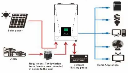
One detection device needs be connected between the PV + and PV- & the ground, to ensure leakage current between PV + and PV- & the ground is less than 30mA. Isolation transformer Specs. : 1 0KW-220:220V 60*10 0 single phase Isolation transformer.
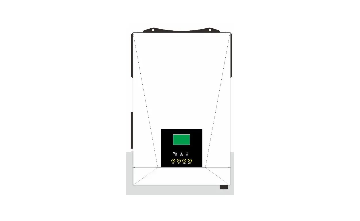
Product Overview
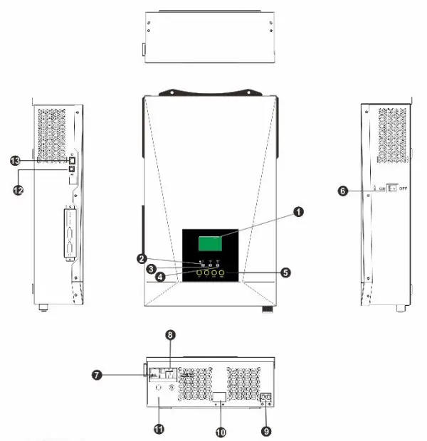
- LCD display
- Status indicator
- Charging indicator
- Fault indicator
- Function buttons
- Power on/off switch
- AC input
- AC output
- PV input
- Battery input
- Circuit breaker
- USB communication port
- RS-232 communication port
INSTALLATION
Unpacking and Inspection
Before installation, please inspect the unit. Be sure that nothing inside the package is damaged. You should have received the following items inside of package:
- The unit x 1
- User manual x 1
- Communication cable x 1
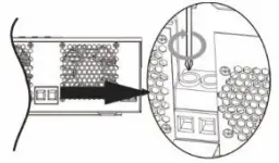
Preparation
Before connecting all wirings, please take off bottom cover by removing two screws as shown below. 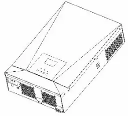
Mounting the Unit
Consider the following points before selecting where to install:
- Do not mount the inverter on flammable construction materials.
- Mount on a solid surface
- Install this inverter at eye level in order to allow the LCD display to be read at all times.
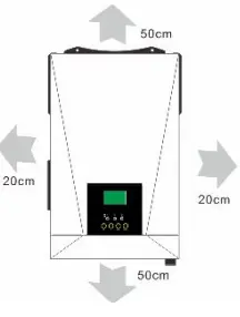
- For proper air circulation to dissipate heat, allow a clearance of approx. 20 cm to the side and approx. 50 cm above and below the unit.
- The ambient temperature should be between O’C and 55’C to ensure optimal operation.
- The recommended installation position is to have adhered to the wall vertically.
- Be sure to keep other objects and surfaces as shown in the diagram to guarantee sufficient heat dissipation and to have enough space for removing wires.
Install the unit by screwing two screws. It’s recommended to use M4 or M5 screws. 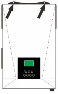
Battery Connection
CAUTION:
For safety operation and regulation compliance, it’s requested to install a separate DC over-current protector or disconnect device between battery and inverter. It may not be requested to have a disconnect device in some applications, however, it’s still requested to have over-current protection installed. Please refer to typical amperage in below table as required fuse or breaker size.
WARNING!
All wiring must be performed by qualified personnel.
WARNING!
It’s very important for system safety and efficient operation to use appropriate cable for battery connection. To reduce risk of injury, please use the proper recommended cable as below. Recommended battery cable size: 
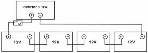
Please follow below steps to implement battery connection: 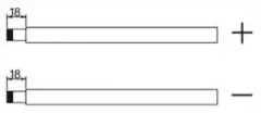
- Remove insulation sleeve 18 mm for positive and negative conductors.
- Suggest to put bootlace ferrules on the end of positive and negative wires with a proper crimping tool.

- Insert the battery wires flatly into battery connectors of inverter and make sure the bolts are tightened with torque of 2 Nm in clockwise direction. Make sure polarity at both the battery and the inverter/charge is correctly connected and conductors are tightly screwed into the battery terminals. Recommended tool: #2 Pozi Screwdriver

WARNING: Shock Hazard
Installation must be performed with care due to high battery voltage in series.
CAUTION!!
Before making the final DC connection or closing DC breaker/ disconnector, be sure positive(+) must be connected to positive(+) and negative (-) must be connected to negative(-).
AC Input/Output Connection
CAUTION
Before connecting to AC input power source, please install a separate AC breaker between inverter and AC input power source. This will ensure the inverter can be securely disconnected during maintenance and fully protected from over current of AC input. The recommended spec of AC breaker is 50A for 5.5KW.
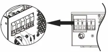
CAUTION!! There
are two terminal blocks with “IN” and “OUT” markings. Please do NOT misconnect input and output connectors.
WARNING!
All wiring must be performed by qualified personnel.
WARNING!
It’s very important for system safety and efficient operation to use appropriate cable for AC input connection. To reduce risk of injury, please use the proper recommended cable size as below.
Suggested cable requirement for AC wires 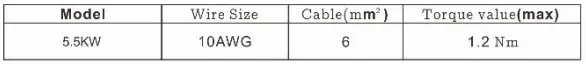
Please follow below steps to implement AC input/output connection:
- Before making AC input/output connection, be sure to open DC protector or disconnector first.
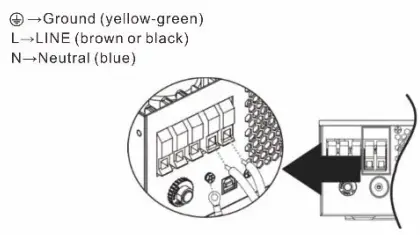
- Remove insulation sleeve 10mm for six conductors. And shorten phase Land neutral conductor N 3 mm.
- For 5.5KW models, insert AC input wires according to polarities indicated on terminal block and tighten the terminal screws. Be sure to connect PE protective conductor first.


- Then, insert AC output wires according to polarities indicated on terminal block and tighten terminal screws. Be sure to connect PE protective conductor first.

- Make sure the wires are securely connected.

CAUTION:
Appliances such as air conditioners are required at least 2~3 minutes to restart because it’s required to have enough time to balance refrigerant gas inside of circuits. If a power shortage occurs and recovers in a short time, it will cause damage to your connected appliances. To prevent this kind of damage, please check manufacturer of air conditioner if it’s equipped with time-delay function before installation. Otherwise, this inverter/charger will trigger overload fault and cut off output to protect your appliance but sometimes it still causes internal damage to the air conditioner.
PV Connection
CAUTION:
Before connecting to PV modules, please install separately a DC circuit breaker between inverter and PV modules.
WARNING!
It’s very important for system safety and efficient operation to use appropriate cable for PV module connection. To reduce risk of injury, please use the proper recommended cable size as below. 
PV Module Selection:
When selecting proper PV modules, please be sure to consider below parameters:
- Open circuit Voltage (Voe) of PV modules does not exceed max. PV array open circuit voltage of inverter.
- Open circuit Voltage (Voe) of PV modules should be higher than min. battery voltage.

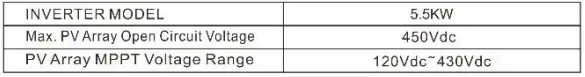
Take 250Wp PV module as an example. After considering above two parameters, the recommended module configurations for 5.5KWare listed as below table. 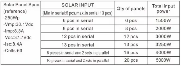
Final Assembly
After connecting all wirings, please put bottom cover back by screwing two screws as shown below. 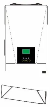
Communication Connection
Please use supplied communication cable to connect to inverter and PC. Insert bundled CD into a computer and follow on-screen instructions to install the monitoring software. For the detailed software operation, please check user manual of software inside of CD.
OPERATION
Power ON/OFF 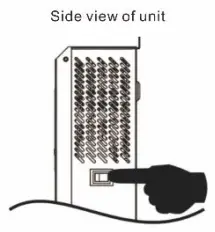
Once the unit has been properly installed and the batteries are connected well, simply press On/Off switch (located on the button of the case) to turn on the unit.
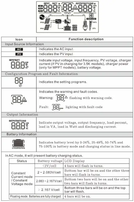
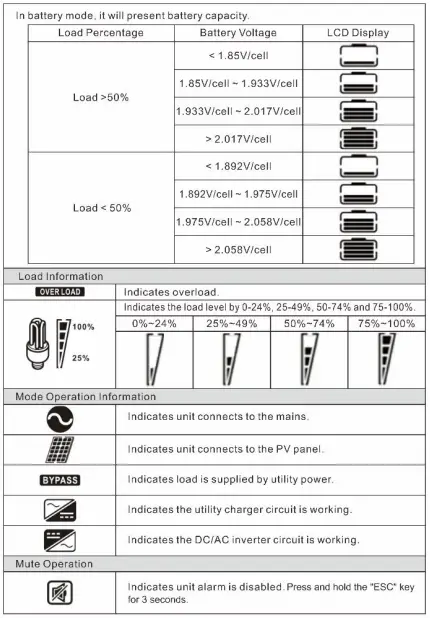
Operation and Display Panel
The operation and display panel, shown in below chart, is on the front panel of the inverter. It includes three indicators, four function keys and a LCD display, indicating the operating status and input/output power information. 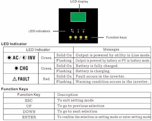
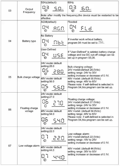
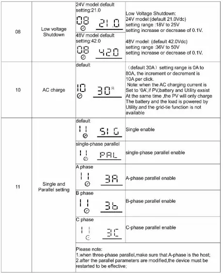
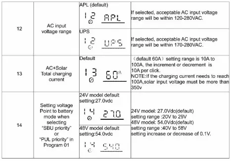
LCD Setting
After pressing ENTER butto the unit will enter setting mode. Press “UP” or ”DOWN” button to select setting programs. And then, press ”ENTER” button to confirm the selection or ESC button to exit 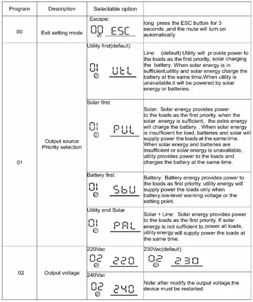
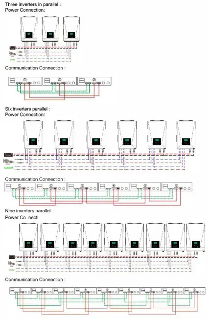
Parallel function operation instructions
( Maximum of nine parallel machines )
Single phase parallel:
- CAUTION: It is forbidden for inverters to share the same solar panel group.
- Connecting the parallel communication line and power cable as shown below
Warning: All inverters must share the same battery pack when paralleling. - Set the parameters of each inverter separately (working mode, single-phase parallel function). Warning: When working in parallel, the working mode of each inverter must be the same working mode, output voltage.frequency.
- After setting the parameters, tum on each inverter in turn.
WRINGING: for each group of PV, only one inverter can be connected, otherwise, it may damage inverters.
Two inverters in parallel: Power Connection: 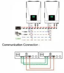
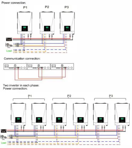
Three-phase parallel:
- CAUTION: It is forbidden for inverters to share the same solar panel group,
- Connecting the parallel communication line and power cable as shown below
Warning: All inverters must share the same battery pack when paralleling - Set the parameters of each inverter independently (working mode, single-phase parallel function, threephase parallel function and set NBIC phase sequence).
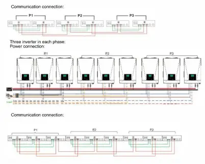
Warning: When working in parallel, the working mode of each inverter must be the same working mode. - After setting the parameters, first turn on the A phase inverter and then turn on each inverter in turn. One inverter in each phase:
WRINGING: Do not connect the current sharing cable between the inverters which are in different phases, Otherwise, it may damage inverters.
Fault Reference Code
| Fault code | Fault event |
| 01 02 | Bus voltage is too high
Inverter voltage is too high |
| 03 | Inverter voltage is too low |
| 04 | Bus soft start failure |
| 05 | Overload fault |
| 06 | Output short-circuited |
| 07 | Battery voltage is too low |
| 08 | Inverter soft start failure |
| 09 | Bus voltage is too low |
| 10 | Parallel fault |
| 11 | Over temperature |
| 12 | Battery voltage is too high |
| 13 | A phase lost |
| 14 | B phase lost |
| 15 | C phase lost |
| 16 | AC output voltage and frequency setting is different |
| 17 | AC input voltage and frequency detected different |
| 18 | Power feedback protection |
| 19 | Firmware version inconsistent |
| 20 | Current sharing fault |
| 23 | PV is over current |
| 24 | PV over temperature |
Warning Indicator
| Warning code | Warning Event |
| 01 | Battery voltage is too low |
| 02 | Input voltage is too low |
| 03 | Input voltage is too high |
| 04 | Overload |
| 05 | Over temperature |
| 06 | Fan is locked when inverter is on |
| 07 | Battery voltage is too high |
| 21 | PV voltage is too low |
| 22 | PV voltage is too high |
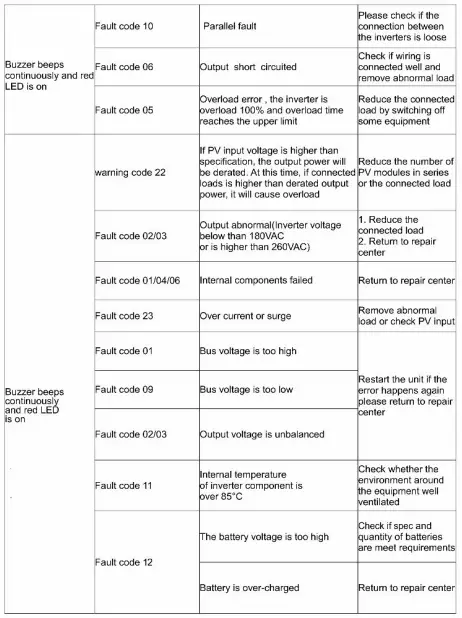
TROUBLESHOOTING
| Problem | LCD/LED/Buzzer | Possible cause | What to do |
|
Unit shuts down automatically during start-up process |
LCD/LED and buzzer will be active then complete off |
The battery voltage is too low |
1. Re-charge battery. 12. Replace battery |
|
No response after power on |
No indication |
1. The battery voltage is too low. 2. Internal fuse tripped | 1. Contact repair !Center for replacing the fuse. 12. Re-charge battery. 13. Replace battery. |
|
Mains exist but the unit works in battery mode | Input voltage is displayed as ‘O’ on the LCD and green LED is flashing |
Input protector is triggered | heck if ACbreaker is turned on and AC r–,,iring is connected r–,,ell. |
|
LED is flashing | 1. Check if AC wires are too thin and/or too | ||
| long. | |||
| Insufficient quality of AC power | 12-Check if generator (if applied) is working r–,, ell or if input voltage range setting is incorrect | ||
| When the unit is turned on, internal relay is switched on and off repeatedly |
LCD display and LED flashing |
Battery is disconnected |
!Check if battery wires are connected well |
|
Buzzer beeps continuously and red LED is on | warning code 06 | Fan fault | Replace the fan |
|
warning code 05 | h Internal temperature of inverter component is over 85°C | check whether the environment around he equipment well ventilated | |
|
warning code 07 |
The battery voltage is too high u | !Check if spec sanctity of batteries are meet requirements | |
| Battery is over-charged | Return to repair center | ||
|
Buzzer beeps continuously and red LED is on | fault code 13/14/15 | Phase loss | 1. check whether three-phase power is connected 2. check whether the inverter turns on three-phase parallel | |
| Check whether the output voltage and frequency of each inverter are set the same | ||||
| fault code 16 | fC output voltage and frequency setting is different | |||
| Fault code 17 | C input voltage and frequency detected different | Check whether the input voltage and frequency of each inverter are set the same | ||
| 1. restart the inverter. 2. check if UN cables are not Connected reversely in all inverters. 3. for parallel system in single phase, make sure the sharing are connected in all inverters. To supporting three-phase system. make sure the sharing Cables are connected in the inverters in the same phase. | ||||
| Fault code 18 | Power feedback protection | |||
| [And disconnected in the | ||||
| inverters in different phase. | ||||
|
Fault code 19 |
Firmware version inconsistent | 1. update all inverter firmware to the same version 2. if the problem remains, please contact your installer. | ||
SPECIFICATIONS
Table 1 Solar Mode specifications
| MODEL | 5.5KVA 48VDC |
| Rated output power | 5.5KVA/5.5KW |
| PV Max power | 5500W |
| PV operating voltage range | 120-450VDC |
| PV normal operating voltage | 280-360VDC |
| Normal output voltage | 230VAC |
| Output voltage range | 230 ± 5%VAC |
| Normal output current | 24A |
| Power factor | 1.0 |
| Efficiency(DC/AC) | e!:92% |
| Frequency | 50/60Hz |
| Overload protection | MPPT will close immediately as long as the input power is greater than the maximum output power |
| PV Max input current | 20A |
Table 2 Line Mode specifications
| Input Voltage Waveform | Pure sine wave (utility or generator) |
| Normal Input Voltage | 230VAC |
| Low Loss Voltage | 120VAC±7V ( wide range) 170VAC±7V(narrow range) |
| Low Loss Return Voltage | 130VAC±7V ( wide range) 180VAC±7V(narrow range) |
| High Loss Voltage | 280VAC±7V |
| High Loss Return Voltage | 270VAC±7V |
| Max AC Input Voltage | 300VAC |
| Normal Input Frequency | 50Hz / 60Hz (Auto detection) |
| Low loss Frequency | 40±1Hz |
| Low loss Return Frequency | 42±1Hz |
| High loss Frequency | 70±1Hz |
| High loss Return Frequency | 69±1Hz |
| Output short circuit protection | Circuit Breaker |
| Efficiency (Line Mode) | >95% ( Rated R load, battery full charged ) |
| Communication | USB or RS232 or WIFI |
| Humidity | 0-90% RH( No-condensing) |
| Operation temperature | -10-50°C |
Table 3 Charge Mode specifications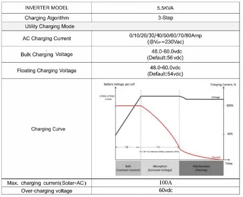
Table 4 Inverter Mode specifications
| Normal DC voltage | 48V |
| Waveform | Pure sine wave |
| Output voltage range | 230VAC±5% |
| Output frequency | 50/60Hz±1Hz |
| Peak Efficiency | .:90% |
| Power factor | 1.0 |
| Overload protection | 20s@101%-120% load ,10s@121%-150% load, 5s@.:150% load |
| Transfer time | 1Oms typical (UPS); 20ms typical (Appliances) |
| Protection features | Low voltage protection; High voltage protection Overload protection ; Over-temperature protection Short circuit protection; Over-charge protection; Battery reverse protection |
| Cold start voltage | 46.0VDC |
| Low voltage alarm(optional) | 36.0-50.0VDC |
| Low voltage alarm recovery | 44.0VDC |
| Low voltage shutdown(optional) | 36.0-50.0VDC |
| High voltage alarm recovery | 60.0VDC |
| Dimension( LxWxH)mm | 498X313X123 |
| Net Weight (KG) | 10.0 |
| Gross Weight (KG) | 11.3 |


