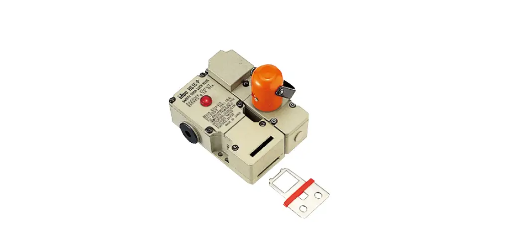
IDEC HS1C-P Interlock Plug Unit with Door Lock
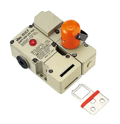
Interlock plugs with door lock mechanism for high level safety management.
- Installing the actuator on the guard door and the interlock switch on the machine, the guard door can be auto-locked mechanically.
- Removing the interlock plug maintains the interrupted status of load circuit and control circuit.
- Solenoid type and non-solenoid type available
- Solenoid type has a lock mechanism. Lock mechanism pre-vents removal of interlock plug during machine operation, and allows for removal after the machine has stopped, with sole-noid energization signal.
- Flexible installation: The actuator can be inserted into two direction.
- Rugged die-cast aluminum housing
- UL listed, c-UL listed.

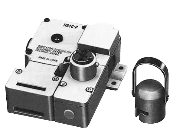
Interlock Plug Unit
| Solenoid | Part No . |
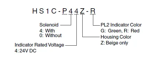
| With solenoid (24V DC) | HS1C-P44Z-➁ |
| Without solenoid | HS1C-P04Z-➁ |
- Specify an indicator color code in place of ➁ in the Part No. G: green, R: red
- Key wrench for TORX screws (HS9Z-T1) is supplied.
- Actuator is not supplied and must be ordered separately.
Actuators
| Description | Part No . |
| Straight Actuator | HS9Z-A1 |
| Right-angle Actuator | HS9Z-A2 |
| Angle Adjustable Actuator (for hinged doors) | HS9Z-A3 |
| Key wrench for TORX screws | HA9Z-T1 |
Rating Circuit
| Model | HS1C-P44Z | HS1C-P04Z | |
| Main Circuit | Rated Insulation Voltage (Ui) | 250V (100% duty cycle) | |
| Rated Thermal Current (Ith) | 10A | ||
| Rated Insulation Voltage (Ui) | 250V | ||
| Rated Thermal Current (Ith) | 3A | ||
| Monitor | Rated Operating Voltage (Ue) | 250V AC | |
| Circuit | 0 .1A | 3A | |
| Rated Operating Current (Ie) | 250V AC/ 30V DC | (250V AC/ 30V DC) | |
| (resistive load) | (resistive load) | ||
Solenoid Unit
| Rated Voltage | 24V DC |
| Rated Current | 260 mA |
| Coil Resistance | 95Ù (at 20°C) |
| Pickup Voltage | Rated voltage × 90% maximum (at 20°C) |
| Dropout Voltage | Rated voltage × 10% minimum (at 20°C) |
| Maximum Continuous Applicable Voltage | Rated voltage × 110% |
| Maximum Continuous Applicable Time | Continuous |
| Power Consumption | 6 .3W |
Indicator
| Rated Voltage | 24V DC |
| Rated Current | 10 mA |
| Light Source | LED |
| Lens Color | G (green), R (red) |
- The lens cannot be replaced.
Specifications
|
Applicable Standards | Main Circuit | UL508 (UL listed) CSA C22 .2, No . 14 (c-UL listed) UL498 CSA C22 .2 No . 182 .1 |
| Auxiliary Circuit | UL508 (UL listed) CSA C22 .2, No . 14 (c-UL listed) | |
| Applicable Standards for Use | EN 1088 | |
| Operating Temperature | –20 to +50°C (no freezing) | |
| Relative Humidity | 45 to 85% (no condensation) | |
| Storage Temperature | –40 to +80°C (no freezing) | |
| Pollution Degree | 3 | |
| Insulation Resistance | 100 MΩ minimum (500V DC megger) | |
| Contact Resistance | 100 mÙ maximum (initial value) | |
| Dielectric Strength | Between live and dead metal parts: 2000V, 1 minute Between terminals of the same poles: 1000V, 1 minute | |
| Shock Resistance | Damage limits: 1000 m/s2 | |
| Vibration Resistance | Operating extremes: 10 to 55 Hz, amplitude 0 .5 mm minimum Damage limits: 30 Hz, amplitude 1 .5 mm minimum | |
| Operating Frequency | 900 operations per hour (actuator, plug) | |
| Mechanical Life | 30,000 operations minimum (actuator, plug) | |
| Actuator Retention Force | 1500N minimum | |
| Interlock Plug Strength | Rotational strength when locked: 5 N·m | |
| Mounting Screw | M5 × 4 | |
| Weight (approx .) | 720g (HS1C-P44Z-➁) | |
Part No. Development
Dimensions
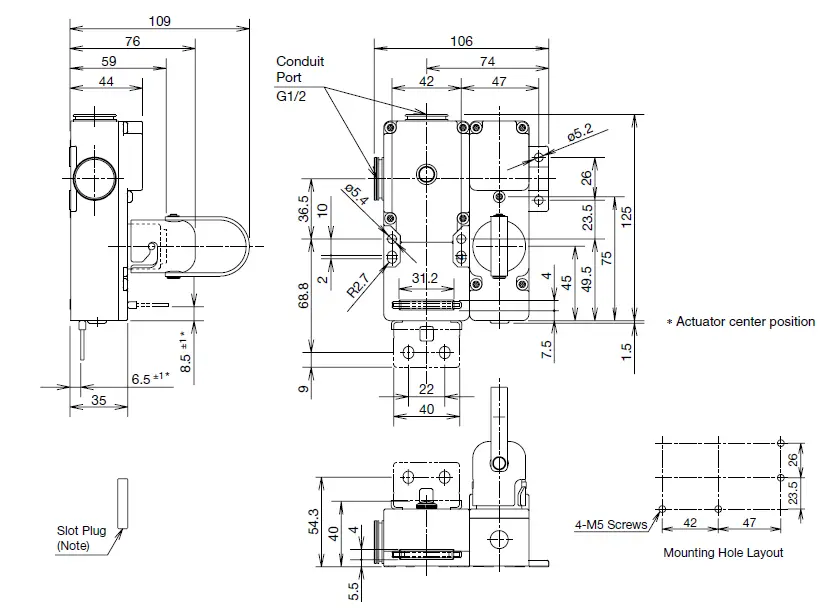
Note: Plug the unused actuator entry slot using the slot plug supplied with the interlock switch.
- Use four mounting screws to mount the interlock switch according to the mounting hole layout.
Actuator Dimensions
Straight Actuator HS9Z-A1
Right-angle Actuator HS9Z-A2
Angle-adjustable Actuator HS9Z-A3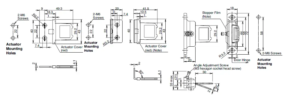
Note: The actuator cover and actuator stop films are supplied with the actuator and used when adjusting the actuator position.
Remove the actuator cover and actuator stop film after the actuator position is determined.
Circuit Diagrams and Operating Characteristics
With Solenoid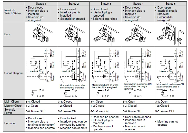
Without Solenoid 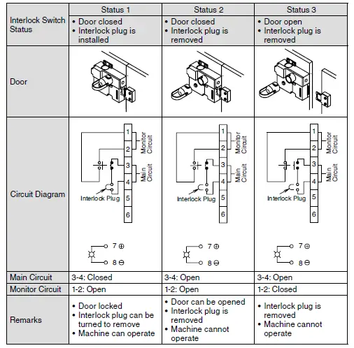
Safety Precautions
- Do not install the interlock plug unit with door lock in the place subject to oil or water. Electric shocks or fire hazards may be caused if the interlock plug is operated when the plug part is contaminated with oil or water.
- Interlock plug units with door lock are used to ensure the safety of operators who carry the plugs. Provide only one plug to a guard. Otherwise the hostage control function is lost, endangering the operators. Ensure complete safety manage-ment so that the function is maintained.
- In order to avoid electric shocks or fire, turn the power off before installation, removal, wire connection, maintenance, or inspection of the interlock plug unit.
- Do not disassemble or modify the interlock plug unit with door lock Also do not disable the function of the interlock plug unit intentionally. Otherwise, a malfunction or an accident may occur.
- Do not install the actuator in a location where a human body may come into contact. Otherwise, injury may occur.
Instructions
- The plug of HS1P interlock plug units resemble the HS2P plug, however, these plugs are not interchangeable. Do not use the plugs of other types, otherwise the interlock plug units will be damaged. The plugs can be distinguished with the han dle color.
HS1P: black (sane as HS1C-P)
HS2P: aluminum color - Regardless of door types, do not use the interlock plug unit
- as a door stop. Install a mechanical door stop at the end of the door to protect the interlock plug unit against excessive force. If excessive force is applied to the plug, especially to the direc tion of removing the plug, solenoid operation failure may occur even though the solenoid is energized, resulting in unlocking failure.
- Do not apply excessive shock to the interlock plug unit when opening or closing the door. A shock to the interlock plug unit exceeding 1,000 m/s2 may cause damage to the interlock plug unit.
- Regardless of door types, do not use the interlock plug unit as a door lock. Install a separate lock using a latch or other mea sures.
- The solenoid has polarity. Make sure of the correct polarity when wiring. Do not apply overvoltage, otherwise the solenoid will be burnt.
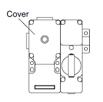
- When wiring, unscrew the cover only. Unnecessary loosening of other screws may cause a malfunction of the interlock plug unit.

- The cover uses special screws which cannot be removed or tightened by general drivers. Use the special wrench supplied with the interlock plug unit.
- While connecting to the conduit port, prevent foreign objects from entering the interlock plug unit, such as dust and liquids.
- If the operating atmosphere is contaminated, use a protective cover to prevent the entry of foreign objects into the interlock plug unit through the actuator entry slots.
- Entry of a considerable amount of foreign objects into the interlock plug unit may affect the mechanism of the interlock plug unit and cause a malfunction.
- Actuator retention force is 1500N (static load). When larger force is expected, add a system using interlock switch without lock (ex. HS1B) and sensor in order to detect door opening and to stop the machine.
- Plug the unused actuator entry slot using the slot plug sup-plied with the interlock plug unit.
- Do not store the interlock plug unit in a dusty, humid, or organic-gas atmosphere.
- Make sure that the interlock plug unit is not energized when removing or installing the plug (after operating the emergency stop button shown in the circuit example shown below). Do not start or stop the machine by plug removal/installation, otherwise, the interlock plug unit may fail.
Interlock Plug +
Circuit Example
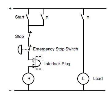
Note 1: When using the main circuit on AC, connect emergency stop switch to Line, and interlock plug unit to Neutral.
Note 2: When using the main circuit on DC, connect to the + line with emergency stop switch first followed by the interlock plug unit.
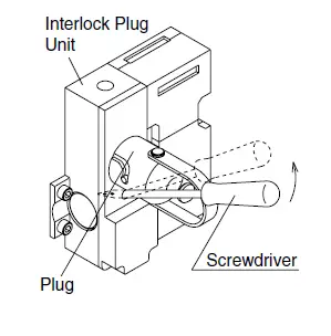
Manual Unlocking
The HS1C-P allows manual unlocking of the actuator to pre-check proper entry of the actuator into the slot as well as for emergency use such as a power failure.
- Remove the screw located on the front of the interlock plug unit using the special wrench supplied with the interlock plug unit. Insert a small screwdriver into the screw hole and push the lever inside as shown below until the key is unlocked.
- Turn and remove the plug.
- After unlocking, ensure to install the screw.

Instructions
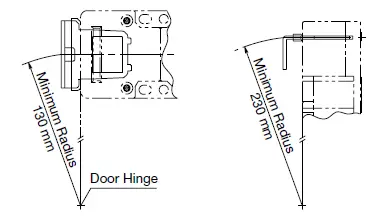
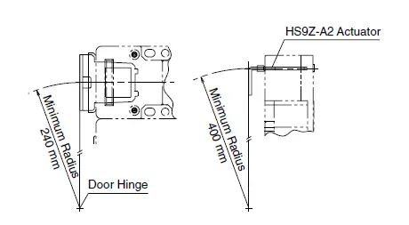
Minimum Radius of Hinged Door
- When using the interlock plug unit for a hinged door, refer to the minimum radius of doors shown below. For the doors with small minimum radius, use angle adjustable actuators (HS9Z-A3).
Note: Because deviation or dislocation of hinged door may occur in actual applications, make sure of the correct operation before installation.|
HS9Z-A2 Actuator - When the door hinge is on the extension line of the interlock plug unit surface:

- When the door hinge is on the extension line of the actuator mounting surface:
 HS9Z-A3 Actuator
 - When the door hinge is on the extension line of the interlock plug unit surface:

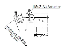
- When the door hinge is on the extension line of the actuator mounting surface:

 HS9Z-A3 Actuator
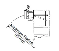
Actuator Angle Adjustment
- Using the angle adjustment screw, the actuator angle can be adjusted (refer to the dimensional drawing). Adjustable angle: 0 to 20°
- The larger the adjusted angle of the actuator, the smaller the ap-plicable radius of the door opening.
- After installing the actuator, open the door. Then adjust the actua-tor so that its edge can be inserted properly into the actuator entry slot of the interlock switch.
- Recommended tightening torque of angle adjustment screw: 0.8 N·m
- After adjusting the actuator angle, apply Loctite to the adjustment screw so that the screw will not loosen.
Applicable Crimping Terminal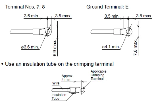
Terminal No. 1 to 6
- Direct wiring using either solid or stranded wires.
- When using stranded wires, make sure that loose wires do not cause short circuit. Also, do not solder the terminal to prevent loose wires.
When using Ferrules Ferrules (Phoenix Contact)
| Part No . | Applicable Wire |
| AI 0 .75-8 GY | 0 .5 to 0 .75 mm2 |
| AI 1 .0-8 RD | 0 .75 to 1 .0 mm2 |
| AI 1 .5-8 BK | 1 .0 to 1 .5 mm2 |
Crimping Tool: CRIMPFOX UD6
Applicable Wire Size
- Terminal Nos. 1, 2, 5, 6, 7, 8: 0.5 to 0.75 mm2
- Terminal Nos. 3, 4, E: 1.0 to 1.25 mm2
Installing the Interlock Plug Unit
Mount the interlock plug unit on a fixed machine or guard, and mount the actuator on the hinged door. Do not mount both the safety plug unit and actuator on the hinged doors, otherwise, malfunction will occur.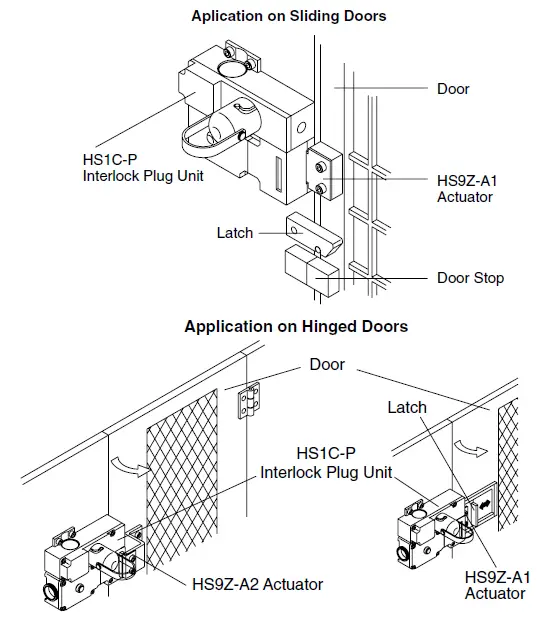
Instructions
Applicable Cable Glands
- Use IP67 cable gland.

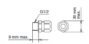
When Using Flexible Conduits (Example) - Flexible conduit example: VF-03 (Nihon Flex) Metal gland example:
- (G1/2) RLC-103 (Nihon Flex)
When Using Multi-core Cables (Example) - Plastic cable gland:
(G1/2) SCS-10* (Seiwa Electric) - Metal cable gland:
(G1/2) ALS-16 (Nihon Flex) - Different cable glands are used depending on the cable sheath outside diameter. When purchasing a cable gland, confirm that the cable gland is applicable to the cable sheath outside diameter.
Recommended Tightening Torque of Mounting Screws
- Interlock switch: 4.5 to 5.5 N·m (four M5 screws)
- Actuator (HS9Z-A1/A2/A3): 4.5 to 5.5 N·m (two M6 screws)
- Mounting bolts must be provided by users.
- The above recommended tightening torques of the mount ing screws are the values confirmed with hex socket head bolts. When other screws are used and tightened to a smaller torque, make sure that the screws do not come loose after mounting.
Cable Lead-in Length and Wiring Examples
| Terminal No . | Conduit Port | ||
| ➀ | ➁ | ||
|
Cable Length L1 (mm) | 1 | 30±2 | 45±2 |
| 2 | 30±2 | 50±2 | |
| 3 | 25±2 | 55±2 | |
| 4 | 25±2 | 60±2 | |
| 5 | 30±2 | 65±2 | |
| 6 | 30±2 | 70±2 | |
| 7 | 65±2 | 35±2 | |
| 8 | 65±2 | 110±2 | |
| E | 85±2 | 45±2 | |
| Wire Stripping Length L2 (mm) | 7±1 | ||
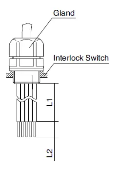
Note: Wire the interlock switches according to the following examples.
When using Conduit Port ➀
When using Conduit Port ➁
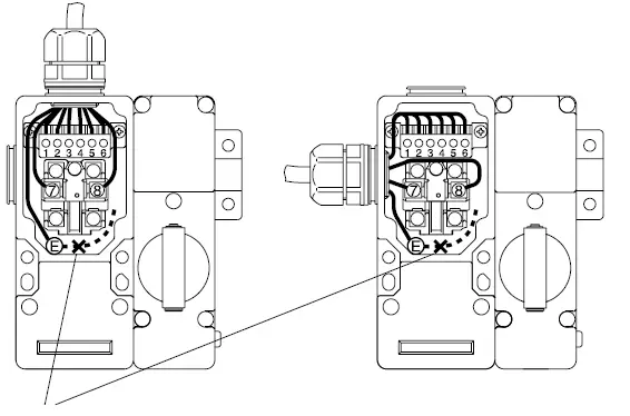
Note: When wiring the ground (E) terminal, connect in the solid line direction only. Do not connect in the dotted line direction.


