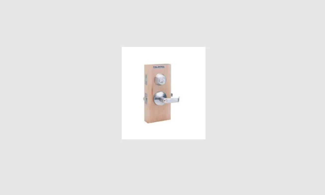
CAL-ROYAL CIL Series Interconnected Locks Instruction
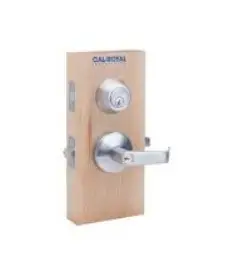
INSTALLATION INSTRUCTIONS FOR CIL INTERCONNECTED LOCKS
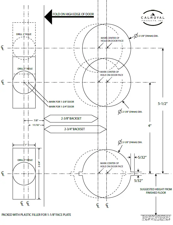
MARK DOOR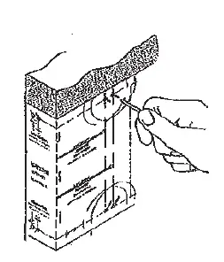
- Check lock for proper backset and door thickness of the door before marking.
- Fold template at correct markings for door.
- Mark appropriate centers for 2- 1/8” (54mm) holes.
- Mark center for 1” (25mm) diameter latch holes in door edge.
DRILL HOLES 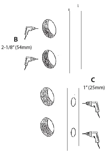
- Determine backset (2-3/4” or 2-3/8”) of the lock.
- Drill the 2-1/8” (54mm) holes about halfway through door face from both sides to avoid damaging wood surface.
- Drill 1” (25mm) diameter holes on door edge.
INSTALL DEADBOLT & LATCHBOLT
ADJUSTABLE DEADBOLT IS FACTORY PRESET 2-3/4” (70MM) BACKSET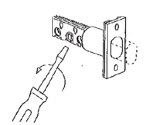
- Bolt must be retracted. Retract bolt. (If necessary, use screw driver to turn cam and retract bolt).
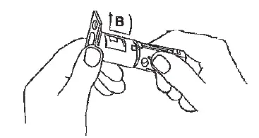
- How to adjust for 2-3/8” (60mm) backset.
NOTE: Rotate faceplate and push down to move housing to next position
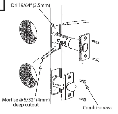
PREPARE DOOR JAMB
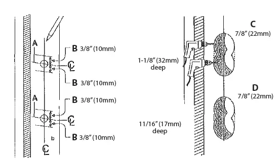
- A. Locate exact centerline of bolt and mark centerline of jamb.
- B. Mark drill points 3/8” (10mm) above and below centerline.
- C. Drill two overlapping 7/8” (22mm) holes 1-1/4” deep for deadbolt. Clean out hole.
- D. Drill two overlapping 7/8” (22mm) holes 11/16” deep for latchbolt into door jamb as shown
INSTALL STRIKE
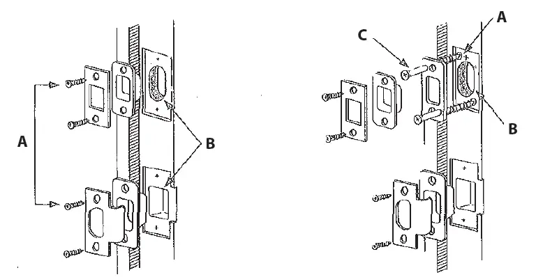
- A. Place strike box in hole. Place strike over the strike box and use it as pattern for cutout.
- B. Chisel about 1/8” (3.2mm) deep for flush fit of box and strike
- C. Install strike box and strike.
- A. Place reinforcer in cutout with screw holes as shown. Mark & drill 3/16 (5mm) pilot holes
- B. Chisel about 1/4” (6mm) deep for flush fit of reinforcer, box and strike.
- C. Install reinforcer with 3” (76mm) wood screws.
- D. Install strike box and strike.
HANDING
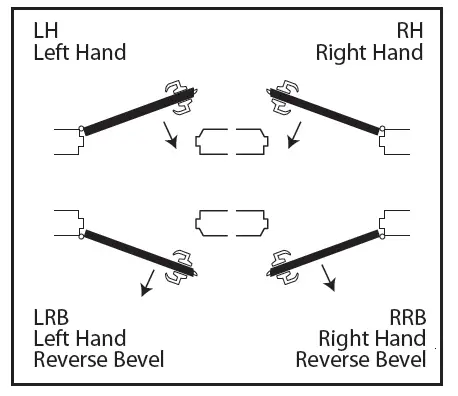
- A. Determine and note your hand of door.
- B. When standing on the exterioir side of the door, and the hinges are to your right, you have a RIGHT HAND DOOR.
- C. If the hinges are to your left, you have a LEFT HAND DOOR.
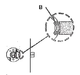
HOW TO CHANGE DOOR HANDING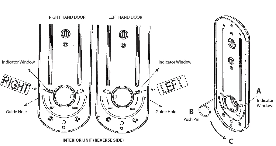
- A. Check if RIGHT-HAND or LEFT-HAND.
- B. Insert push pin (provided) into the guide hole at the end of the semicircle as shown on the following diagram.
- C. While push pin is inserted on the guide hole, move it along the semicircle guide until you see either “LEFT” or “RIGHT” on the indicator window.
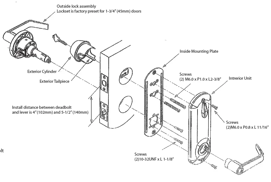
LOCK INSTALLATION 
- A. Remove inside lever from lock, esing push pin.
- B. Install lock assembly into door and engage latch as detailed.
- C. Place inside mounting plate. Tighten it to lock body with two (2) 10-32UNF x L 1-3/8” screws.
- D. Install exterior deadbolt cylinder assembly with tailpiece horizontally.
- E. Tighten inside mounting plate to exterior deadbolt cylinder with two (2) M6.0 x P1.0 x L 2-3/8” screws.
- F. Install interior unit with two (2) M5.0 x P0.8 x L11/16” screws.
- G. Install inside lever.
TEMPLATE FOR CIL INTERCONNECTED LOCKS