MEAN WELL RPT-160 145W Reliable Triple Output Medical Grade
Product Information: 145W Reliable Triple Output Medical Grade
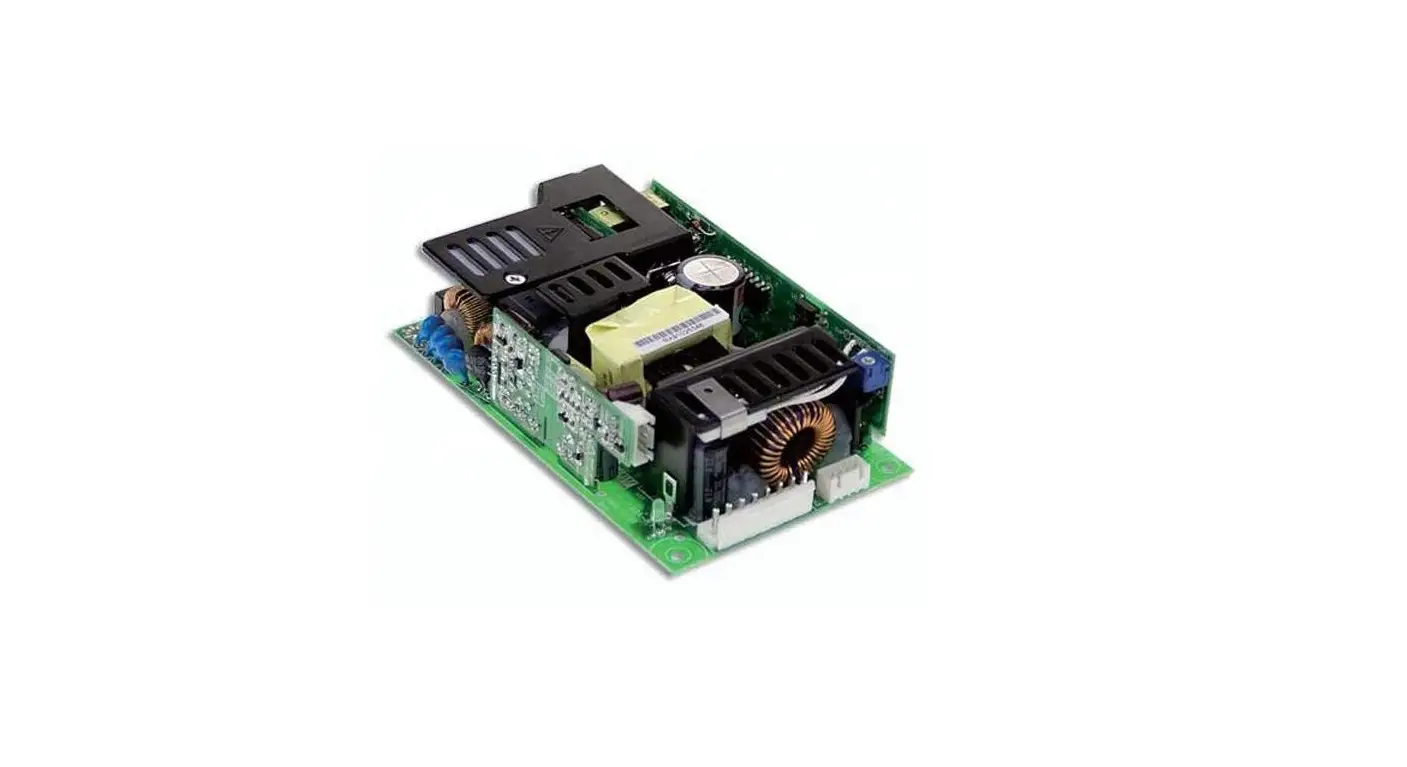
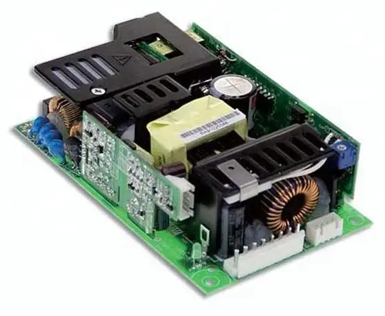
RPT-160 series
The RPT-160 series is a medical-grade power supply with a triple output of 5V, 12V, and -5V. It comes in four different models – RPT(G)-160A, RPT(G)-160B, RPT(G)-160C, and RPT(G)-160D. The power supply has a maximum rated power of 145W and a ripple and noise level of up to 120mVp-p. It has a wide input voltage range of
90-264VAC and a frequency range of 47-63Hz. The power supply is designed to be highly efficient with a typical efficiency rate of 84%. It is also designed to be safe and reliable with various protection features.
Product Usage Instructions
The RPT-160 series power supply is designed for medical applications and should only be used by qualified personnel. Before using the power supply, please read the user manual carefully.
- Connect the input power to the power supply according to the specified input voltage range (90-264VAC).
- Connect the load to the output terminals of the power supply.
The power supply has three output channels – CH1, CH2, and CH3. Each channel has a different voltage and current range as specified in the user manual. - Turn on the power supply using the PS-ON input signal (for G model) or by connecting the input power.
- The power supply has various protection features such as overload protection, overvoltage protection, and over-temperature protection. In case of any fault condition, the power supply will automatically recover after the fault condition is removed.
- The power supply has a wide operating temperature range of -20 to +70 degrees Celsius. However, please refer to the derating curve in the user manual for the recommended operating temperature based on the load conditions.
- When not in use, store the power supply in a dry and cool place with a temperature range of -40 to +85 degrees Celsius and a humidity range of 10-95% RH non-condensing.
- The power supply has undergone various safety and EMC tests and meets the standards specified in the user manual. However, please follow the safety precautions specified in the user manual while using the power supply.
Features
- 5″×3″ compact size
- Medical safety approved (2 × MOPP) according to ANSI/AAMI ES60601-1 and IEC/BS EN/EN 60601-1
- Suitable for BF application with appropriate system consideration
- 100W convection, 145W force air
- EMI Class B for Class I configuration
- No load power consumption<0.75W by PS-ON control (G model)
- Extremely low leakage current
- 5Vdc standby output, Power Good, Power Fail
- Protections: Short circuit / Overload / Over voltage / Over temperature
- Lifetime > 85K hours
- 3 years warranty
Applications
- Oral irrigator
- Hemodialysis machine
- Medical monitors
- Sleep apnea devices
- Pumps machine
Description
RPT(G)-160 is a 145W highly reliable PCB-type medical power supply with a high power density on the 5″ by 3″ footprint. It accepts 90~264 VAC input and offers triple output voltages. The extremely low leakage current is less than 160 MA. In addition, it conforms to international medical regulations (2*MOPP) and EMC BS EN/EN55011, perfectly fitting all kinds of BF-rated “patient contact” medical system equipment. RPT(G)-160 series also offers the enclosed style model [RPT (G)-160-C].
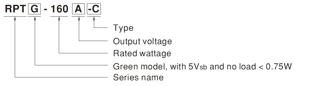
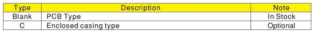
Model Encoding
SPECIFICATION
for PCB Type(standard)
| MODEL | RPT(G)-160A | RPT(G)-160B | RPT(G)-160C | RPT(G)-160D | ||||||||||
|
OUTPUT | OUTPUT NUMBER | CH1 | CH2 | CH3 | CH1 | CH2 | CH3 | CH1 | CH2 | CH3 | CH1 | CH2 | CH3 | |
| DC VOLTAGE | 5V | 12V | -5V | 5V | 12V | -12V | 5V | 15V | -15V | 5V | 12V | 24V | ||
| CURRENT | RATED (20.5CFM) | 14A | 5.5A | 1A | 14A | 5A | 1A | 14A | 3.6A | 1A | 11A | 5A | 1.2A | |
| RANGE (20.5CFM) | 0.6 ~ 14A | 0.2 ~ 5.5A | 0.1 ~ 1A | 0.6 ~ 14A | 0.2 ~ 5A | 0.1 ~ 1A | 0.6 ~ 14A | 0.1 ~ 3.6A | 0.1 ~ 1A | 0.3 ~ 11A | 0.2 ~ 5A | 0.15 ~ 1.2A | ||
| RANGE (convection) | 0.6 ~ 9A | 0.2 ~ 3.8A | 0.1 ~ 0.6A | 0.6 ~ 9A | 0.2 ~ 3.4A | 0.1 ~ 0.8A | 0.6 ~ 9A | 0.1 ~ 2.6A | 0.1 ~ 0.8A | 0.3 ~ 8A | 0.2 ~ 2.6A | 0.15 ~ 1A | ||
| RATED POWER | 20.5CFM Note.2 | 145W | 146W | 143W | 147.8W | |||||||||
| Convection Note.3 | 98.6W | 98.4W | 99W | 98.2W | ||||||||||
| RIPPLE & NOISE (max.) Note.4 | 60mVp-p | 80mVp-p | 120mVp-p | 60mVp-p | 100mVp-p | 100mVp-p | 60mVp-p | 80mVp-p | 100mVp-p | 80mVp-p | 100mVp-p | 120mVp-p | ||
| VOLTAGE ADJ. RANGE | CH1:5 ~ 5.5V | |||||||||||||
| VOLTAGE TOLERANCE Note.5 | ±2.0% | ±5.0% | -5,+7% | ±2.0% | ±5.0% | -4,+5% | ±2.0% | ±4.0% | ±8.0% | ±2.0% | ±5.0% | +7,-5% | ||
| LINE REGULATION | ±0.5% | ±1.0% | ±1.0% | ±0.5% | ±1.0% | ±1.0% | ±0.5% | ±1.0% | ±1.0% | ±0.5% | ±1.0% | ±1.0% | ||
| LOAD REGULATION | ±1.5% | ±3.0% | -5,+6% | ±1.5% | ±3.0% | -4,+5% | ±2.0% | ±3.0% | ±8.0% | ±1.5% | ±3.0% | -3,+4% | ||
| SETUP, RISE TIME | 1800ms, 30ms/230VAC 3500ms, 30ms/115VAC at full load | |||||||||||||
| HOLD UP TIME (Typ.) | 30ms/230VAC 20ms/115VAC at full load | |||||||||||||
|
INPUT | VOLTAGE RANGE Note.6 | 90 ~ 264VAC 127 ~ 370VDC | ||||||||||||
| FREQUENCY RANGE | 47 ~ 63Hz | |||||||||||||
| POWER FACTOR (Typ.) | PF>0.93/230VAC PF>0.98/115VAC at full load | |||||||||||||
| EFFICIENCY (Typ.) | 84% | 84% | 83% | 83% | ||||||||||
| AC CURRENT (Typ.) | 1.8A/115VAC 0.9A/230VAC | |||||||||||||
| INRUSH CURRENT (Typ.) | COLD START 35A/115VAC 70A/230VAC | |||||||||||||
| LEAKAGE CURRENT (max.) Note.7 | Earth leakage current < 160μA/264VAC , Touch current < 100μA/264VAC | |||||||||||||
|
PROTECTION | OVERLOAD | 105 ~ 135% rated output power | ||||||||||||
| Protection type : Hiccup mode, recovers automatically after fault condition is removed | ||||||||||||||
| OVER VOLTAGE | Ch1: 5.7 ~ 6.8V | |||||||||||||
| Protection type : Shut down o/p voltage, re-power on to recover | ||||||||||||||
| OVER TEMPERATURE | TSW1: Shut down o/p voltage, recovers automatically after temperature goes down | |||||||||||||
| TSW2: Shut down o/p voltage, re-power on to recover | ||||||||||||||
| FUNCTION | 5V STANDBY (G model) | 5Vsb : [email protected] without fan, 0.8A with fan 20.5CFM ; Tolerance ± 2%, ripple : 50mVp-p(max.) | ||||||||||||
| PS-ON INPUT SIGNAL (G model) | Power on: PS-ON = “Hi” or ” > 2 ~ 5V” ; Power off: PS-ON = “Low” or ” < 0 ~ 0.5V” | |||||||||||||
| POWER GOOD / POWER FAIL | 500ms>PG>10ms PF>1ms | |||||||||||||
|
ENVIRONMENT | WORKING TEMP. | -20 ~ +70℃ (Refer to “Derating Curve”) | ||||||||||||
| WORKING HUMIDITY | 20 ~ 90% RH non-condensing | |||||||||||||
| STORAGE TEMP., HUMIDITY | -40 ~ +85℃, 10 ~ 95% RH non-condensing | |||||||||||||
| TEMP. COEFFICIENT | ±0.03%/℃ (0 ~ 50℃) | |||||||||||||
| VIBRATION | 10 ~ 500Hz, 2G 10min./1cycle, 60min. each along X, Y, Z axes | |||||||||||||
| OPERATING ALTITUDE Note.8 | 3000 meters | |||||||||||||
|
SAFETY & EMC (Note 10) | SAFETY STANDARDS | IEC60601-1, EAC TP TC 004,UL ANSI/AAMI ES60601-1, CAN/CSA-C22.2 No. 60601-1:14 – Edition 3 approved, TUV BS EN/EN60601-1 approved | ||||||||||||
| ISOLATION LEVEL | Primary-Secondary: 2xMOPP, Primary-Earth:1xMOPP, Secondary-Earth:1xMOPP | |||||||||||||
| WITHSTAND VOLTAGE | I/P-O/P:4KVAC I/P-FG:2KVAC O/P-FG:1.5KVAC | |||||||||||||
| ISOLATION RESISTANCE | I/P-O/P, I/P-FG, O/P-FG:100M Ohms / 500VDC / 25℃/ 70% RH | |||||||||||||
| EMC EMISSION | Parameter | Standard | Test Level / Note | |||||||||||
| Conducted emission | BS EN/EN55011 (CISPR11) | Class B | ||||||||||||
| Radiated emission | BS EN/EN55011 (CISPR11) | Class B | ||||||||||||
| Harmonic current | BS EN/EN61000-3-2 | Class A | ||||||||||||
| Voltage flicker | BS EN/EN61000-3-3 | —– | ||||||||||||
|
EMC IMMUNITY | BS EN/EN60601-1-2 | |||||||||||||
| Parameter | Standard | Test Level / Note | ||||||||||||
| ESD | BS EN/EN61000-4-2 | Level 4, 15KV air ; Level 4, 8KV contact | ||||||||||||
| RF field susceptibility | BS EN/EN61000-4-3 | Level 3, 10V/m( 80MHz~2.7GHz ) Table 9, 9~28V/m( 385MHz~5.78GHz ) | ||||||||||||
| EFT bursts | BS EN/EN61000-4-4 | Level 3, 2KV | ||||||||||||
| Surge susceptibility | BS EN/EN61000-4-5 | Level 3, 2KV/Line-FG ; 1KV/Line-Line | ||||||||||||
| Conducted susceptibility | BS EN/EN61000-4-6 | Level 3, 10V | ||||||||||||
| Magnetic field immunity | BS EN/EN61000-4-8 | Level 4, 30A/m | ||||||||||||
| Voltage dip, interruption | BS EN/EN61000-4-11 | 100% dip 1 periods, 30% dip 25 periods, 100% interruptions 250 periods | ||||||||||||
| OTHERS | MTBF | 1719.1K hrs min. Telcordia SR-332 (Bellcore) ; 175.1K hrs min. MIL-HDBK-217F (25℃) | ||||||||||||
| DIMENSION (L*W*H) | PCB type: 127*76.2*34.6mm or 5″*3″*1.36″ inch | |||||||||||||
| PACKING | 0.33Kg; 36pcs/12.9Kg/0.96CUFT | |||||||||||||
| NOTE | 1. All parameters NOT specially mentioned are measured at 230VAC input, rated load and 25°C of ambient temperature. 2. The rated power includes 5Vsb @ 0.8A. 3. The rated power includes 5Vsb @ 0.6A. 4. Ripple & noise are measured at 20MHz of bandwidth by using a 12″ twisted pair-wire terminated with a 0.1 uf & 47 f parallel capacitor. 5. Tolerance : includes set up tolerance, line regulation and load regulation. 6. Derating may be needed under low input voltages. Please check the derating curve for more details. 7. Touch current was measured from primary input to DC output. 8. The ambient temperature derating of 3.5°C/1000m with fanless models and of 5°C/1000m with fan models for operating altitude higher than 2000m(6500ft) 9. HS1,HS2 & HS3 can not be shorted. 10. The power supply is considered a component which will be installed into a final equipment. All the MC tests are been executed by mounting the unit on a 360mm*360mm metal plate with 1mm of thickness. The final equipment must be re-confirmed that it still meets MC directives. For guidance on how tc perform these MC tests, please refer to “EMI testing of component power supplies.” (as available on http://www.meanwell.com) % Product Liability Disclaimer: For detailed information, please refer to https://www.meanwell.com/service Disclaimer.asp https://www.meanwell.com/serviceDisclaimer.aspx | |||||||||||||
SPECIFICATION for Enclosed Type(optional)
| MODEL | RPT(G)-160A-C | RPT(G)-160B-C | RPT(G)-160C-C | RPT(G)-160D-C | ||||||||||||
|
OUTPUT | OUTPUT NUMBER | CH1 | CH2 | CH3 | CH1 | CH2 | CH3 | CH1 | CH2 | CH3 | CH1 | CH2 | CH3 | |||
| DC VOLTAGE | 5V | 12V | -5V | 5V | 12V | -12V | 5V | 15V | -15V | 5V | 12V | 24V | ||||
| CURRENT | RATED (20.5CFM) | 13.3A | 5.2A | 0.95A | 13.3A | 4.8A | 0.95A | 13.3A | 3.4A | 0.95A | 10.5A | 4.8A | 1.14A | |||
| RANGE (20.5CFM) | 0.6 ~ 13.3A | 0.2 ~ 5.2A | 0.1 ~ 0.95A | 0.6 ~ 13.3A | 0.2 ~ 4.8A | 0.1 ~ 0.95A | 0.6 ~ 13.3A | 0.1 ~ 3.4A | 0.1 ~ 0.95A | 0.3 ~ 10.5A | 0.2 ~ 4.8A | 0.15 ~ 1.14A | ||||
| RANGE (convection) | 0.6 ~ 8.5A | 0.2 ~ 3.6A | 0.1 ~ 0.57A | 0.6 ~ 8.5A | 0.2 ~ 3.2A | 0.1 ~ 0.76A | 0.6 ~ 8.5A | 0.1 ~ 2.5A | 0.1 ~ 0.76A | 0.3 ~ 7.6A | 0.2 ~ 2.5A | 0.15 ~ 0.95A | ||||
| RATED POWER | 20.5CFM Note.2 | 137.7W | 139.5W | 135.8W | 141.5W | |||||||||||
| Convection Note.3 | 91.6W | 93W | 94.4W | 93.8W | ||||||||||||
| RIPPLE & NOISE (max.) Note.4 | 60mVp-p | 80mVp-p | 120mVp-p | 60mVp-p | 100mVp-p | 100mVp-p | 60mVp-p | 80mVp-p | 100mVp-p | 80mVp-p | 100mVp-p | 120mVp-p | ||||
| VOLTAGE ADJ. RANGE | CH1:5 ~ 5.5V | |||||||||||||||
| VOLTAGE TOLERANCE Note.5 | ±2.0% | ±5.0% | -5,+7% | ±2.0% | ±5.0% | -4,+5% | ±2.0% | ±4.0% | ±8.0% | ±2.0% | ±5.0% | +7,-5% | ||||
| LINE REGULATION | ±0.5% | ±1.0% | ±1.0% | ±0.5% | ±1.0% | ±1.0% | ±0.5% | ±1.0% | ±1.0% | ±0.5% | ±1.0% | ±1.0% | ||||
| LOAD REGULATION | ±1.5% | ±3.0% | -5,+6% | ±1.5% | ±3.0% | -4,+5% | ±2.0% | ±3.0% | ±8.0% | ±1.5% | ±3.0% | -3,+4% | ||||
| SETUP, RISE TIME | 1800ms, 30ms/230VAC 3500ms, 30ms/115VAC at full load | |||||||||||||||
| HOLD UP TIME (Typ.) | 30ms/230VAC 20ms/115VAC at full load | |||||||||||||||
|
INPUT | VOLTAGE RANGE | Note.6 | 90 ~ 264VAC 127 ~ 370VDC | |||||||||||||
| FREQUENCY RANGE | 47 ~ 63Hz | |||||||||||||||
| POWER FACTOR (Typ.) | PF>0.93/230VAC PF>0.98/115VAC at full load | |||||||||||||||
| EFFICIENCY (Typ.) | 84% | 84% | 83% | 83% | ||||||||||||
| AC CURRENT (Typ.) | 1.8A/115VAC 0.9A/230VAC | |||||||||||||||
| INRUSH CURRENT (Typ.) | COLD START 35A/115VAC 70A/230VAC | |||||||||||||||
| LEAKAGE CURRENT (max.) Note.7 | Earth leakage current < 160μA/264VAC , Touch current < 100μA/264VAC | |||||||||||||||
|
PROTECTION | OVERLOAD | 105 ~ 135% rated output power | ||||||||||||||
| Protection type : Hiccup mode, recovers automatically after fault condition is removed | ||||||||||||||||
| OVER VOLTAGE | Ch1: 5.7 ~ 6.8V | |||||||||||||||
| Protection type : Shut down o/p voltage, re-power on to recover | ||||||||||||||||
| OVER TEMPERATURE | TSW1: Shut down o/p voltage, recovers automatically after temperature goes down | |||||||||||||||
| TSW2: Shut down o/p voltage, re-power on to recover | ||||||||||||||||
| FUNCTION | 5V STANDBY (G model) | 5Vsb : [email protected] without fan, 0.8A with fan 20.5CFM ; Tolerance ± 2%, ripple : 50mVp-p(max.) | ||||||||||||||
| PS-ON INPUT SIGNAL (G model) | Power on: PS-ON = “Hi” or ” > 2 ~ 5V” ; Power off: PS-ON = “Low” or ” < 0 ~ 0.5V” | |||||||||||||||
| POWER GOOD / POWER FAIL | 500ms>PG>10ms PF>1ms | |||||||||||||||
|
ENVIRONMENT | WORKING TEMP. | -20 ~ +70℃ (Refer to “Derating Curve”) | ||||||||||||||
| WORKING HUMIDITY | 20 ~ 90% RH non-condensing | |||||||||||||||
| STORAGE TEMP., HUMIDITY | -40 ~ +85℃, 10 ~ 95% RH non-condensing | |||||||||||||||
| TEMP. COEFFICIENT | ±0.03%/℃ (0 ~ 50℃) | |||||||||||||||
| VIBRATION | 10 ~ 500Hz, 2G 10min./1cycle, 60min. each along X, Y, Z axes | |||||||||||||||
| OPERATING ALTITUDE Note.8 | 3000 meters | |||||||||||||||
|
SAFETY & EMC (Note 10) | SAFETY STANDARDS | Design refer to IEC60601-1, EAC TP TC 004,TUV BS EN/EN60601-1(Pending for CB/TUV) | ||||||||||||||
| ISOLATION LEVEL | Primary-Secondary: 2xMOPP, Primary-Earth:1xMOPP, Secondary-Earth:1xMOPP | |||||||||||||||
| WITHSTAND VOLTAGE | I/P-O/P:4KVAC I/P-FG:2KVAC O/P-FG:1.5KVAC | |||||||||||||||
| ISOLATION RESISTANCE | I/P-O/P, I/P-FG, O/P-FG:100M Ohms / 500VDC / 25℃/ 70% RH | |||||||||||||||
| EMC EMISSION | Parameter | Standard | Test Level / Note | |||||||||||||
| Conducted emission | BS EN/EN55011 (CISPR11) | Class B | ||||||||||||||
| Radiated emission | BS EN/EN55011 (CISPR11) | Class B | ||||||||||||||
| Harmonic current | BS EN/EN61000-3-2 | Class A | ||||||||||||||
| Voltage flicker | BS EN/EN61000-3-3 | —– | ||||||||||||||
|
EMC IMMUNITY | BS EN/EN60601-1-2 | |||||||||||||||
| Parameter | Standard | Test Level / Note | ||||||||||||||
| ESD | BS EN/EN61000-4-2 | Level 4, 15KV air ; Level 4, 8KV contact | ||||||||||||||
| RF field susceptibility | BS EN/EN61000-4-3 | Level 3, 10V/m( 80MHz~2.7GHz ) Table 9, 9~28V/m( 385MHz~5.78GHz ) | ||||||||||||||
| EFT bursts | BS EN/EN61000-4-4 | Level 3, 2KV | ||||||||||||||
| Surge susceptibility | BS EN/EN61000-4-5 | Level 3, 2KV/Line-FG ; 1KV/Line-Line | ||||||||||||||
| Conducted susceptibility | BS EN/EN61000-4-6 | Level 3, 10V | ||||||||||||||
| Magnetic field immunity | BS EN/EN61000-4-8 | Level 4, 30A/m | ||||||||||||||
| Voltage dip, interruption | BS EN/EN61000-4-11 | 100% dip 1 periods, 30% dip 25 periods, 100% interruptions 250 periods | ||||||||||||||
| OTHERS | MTBF | 1719.1K hrs min. Telcordia SR-332 (Bellcore) ; 175.1K hrs min. | MIL-HDBK-217F (25℃) | |||||||||||||
| DIMENSION | Enclosed type: 130*86*43mm or 5.11″*3.39″*1.69″ inch | |||||||||||||||
| PACKING | 0.49Kg; 24pcs/12.8Kg/0.77CUFT | |||||||||||||||
| NOTE | 1. All parameters NOT specially mentioned are measured at 230VAC input, rated load and 25°C of ambient temperature. 2. The rated power includes 5Vsb @ 0.8A. 3. The rated power includes 5Vsb @ 0.6A. 4. Ripple & noise are measured at 20MHz of bandwidth by using a 12″ twisted pair-wire terminated with a 0.1 f & 47 f parallel capacitor. 5. Tolerance : includes set up tolerance, line regulation and load regulation. 6. Derating may be needed under low input voltages. Please check the derating curve for more details. 7. Touch current was measured from primary input to DC output. 8. The ambient temperature derating of 3.5°C/1000m with fanless models and of 5°C/1000m with fan models for operating altitude higher than 2000m(6500ft). 9. HS1,HS2 & HS3 can not be shorted. 10. The power supply is considered a component which will be installed into a final equipment. All the MC tests are been executed by mounting the unit on a 360mm*360mm metal plate with 1mm of thickness. The final equipment must be re-confirmed that it still meets MC directives. For guidance on how tc perform these MC tests, please refer to “EMI testing of component power supplies.” (as available on http://www.meanwell.com) ⅚ Product Liability Disclaimer: For detailed information, please refer to https://www.meanwell.com/serviceDisclaimer.aspx | |||||||||||||||
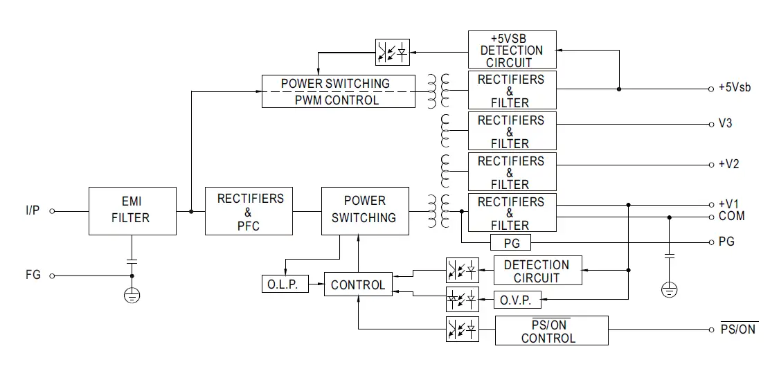
Block Diagram
 Derating Curve
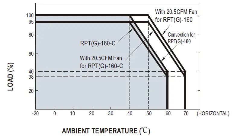
Output Derating VS Input Voltage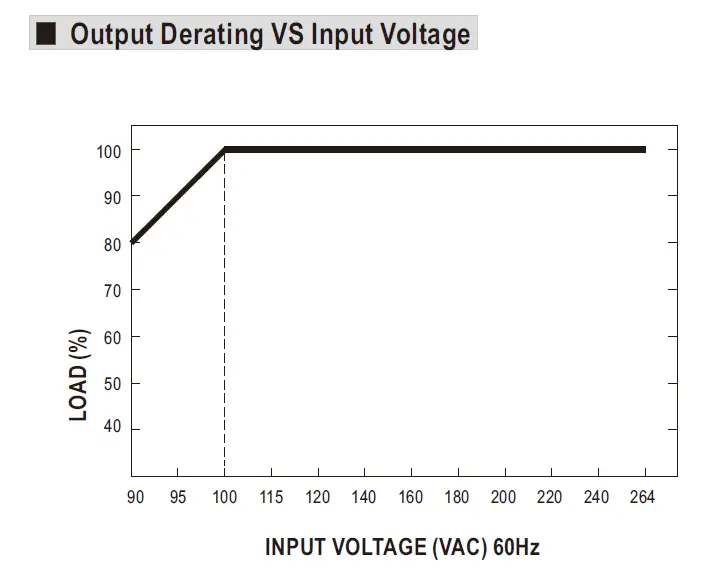
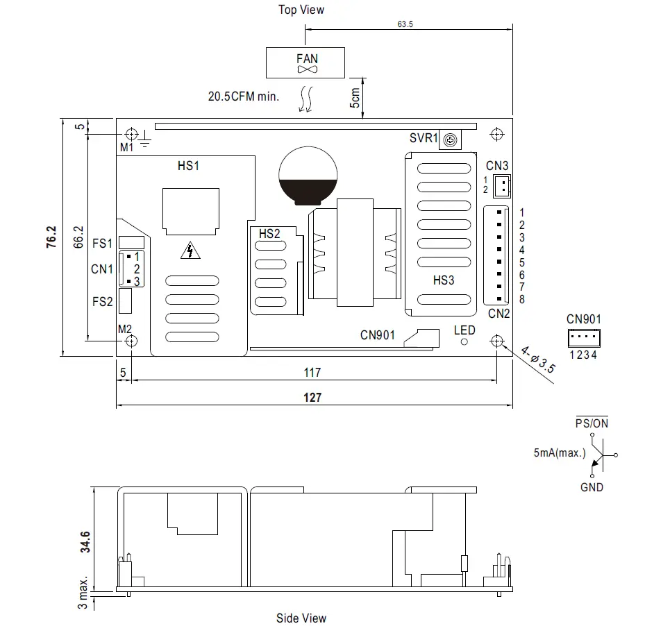
Mechanical Specification
PCB Type: RPT-160(G)
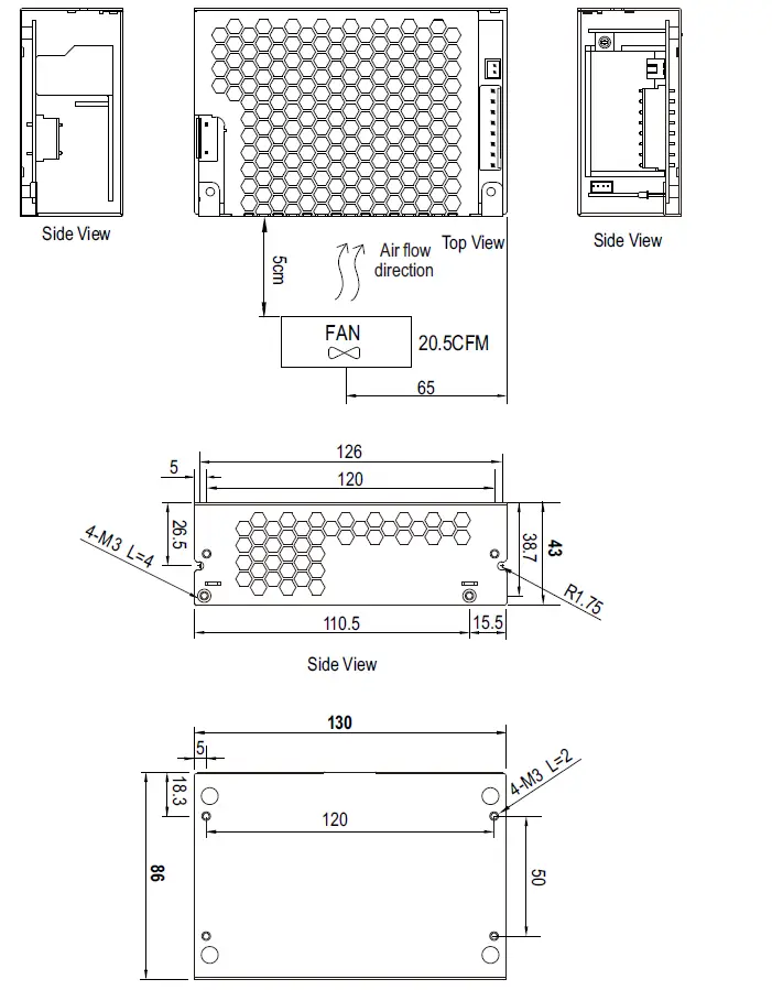
 Enclosed Type: RPT-160(G)-C
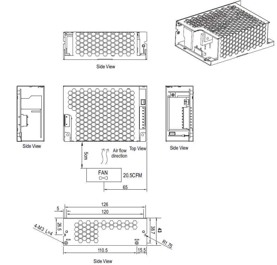
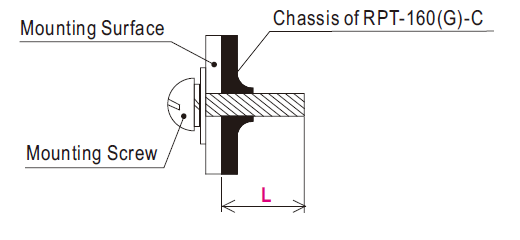
Mounting Instruction
| Hole No. | Recommended Screw Size | MAX. Penetration Depth L | Recommended mounting torque |
| 1 2 | M3 | 2mm | 4~6Kgf-cm |
AC Input Connector (CN1) : JST B3P-VH or equivalent
| Pin No. | Assignment | Mating Housing | Terminal |
| 1 | AC/L | JST VHR or equivalent | JST SVH-21T-P1.1 or equivalent |
| 2 | No Pin | ||
| 3 | AC/N |
DC Output Connector (CN2) : JST B8P-VH or equivalent
| Pin No. | Assignment | Mating Housing | Terminal |
| 1,2,3,4 | COM | JST VHR or equivalent | JST SVH-21T-P1.1 or equivalent |
| 5,6 | CH1 | ||
| 7 | CH2 | ||
| 8 | CH3 |
Power Good Connector(CN3):JST B2B-XH or equivalent
| Pin No. | Status | Mating Housing | Terminal |
| 1 | PG | JST XHP or equivalent | JST SXH-001T-P0.6 or equivalent |
| 2 | GND |
5VSB Connector(CN901) : JST B-XH or equivalent
| Pin No. | Assignment | Mating Housing | Terminal |
| 1 | PS/ON | JST XHP or equivalent | JST SXH-001T or equivalent |
| 2,4 | GND | ||
| 3 | 5VSB |
- HS1, HS2,HS3 can not be shorted
- M1 and M2 are Safety ground and should all be grounded.
Note:
- The PCB type (Blank Type) model delivers EMI Class B for both conducted emission and radiated emission for the power supply when configured into either Class I (with FG).
- The enclosed type (-C type) model is not suitable for configuration within a Class II (no FG) system but is suggested within a Class I (with FG) system.
- Mounting Instruction for Enclosed type only.
INSTALLATION MANUAL
Please refer to: http://www.meanwell.com/manual.html


