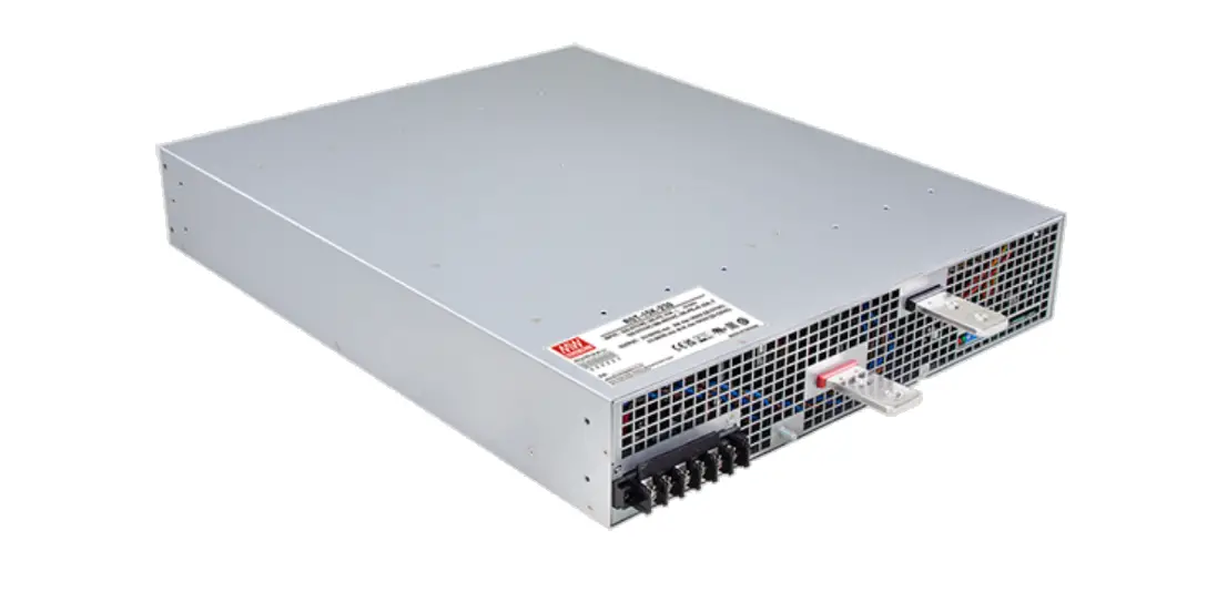
MEAN WELL RST-15K-HV 15KW Input With High Voltage Output

Features
- 3ψ 3-wire / △196~305VAC or 3ψ 4-wire / Y 340~530VAC
- High efficiency up to 94%
- Forced air cooling
- Output voltage and constant current level programmable
- Wide voltage adjustment range 1~120%
- Active current sharing up to 2 units(28.5KW)
- Built-in remote ON-OFF control / Alarm signal
- Protections: Short circuit / Overload / Over voltage / Over temperature / Fan fail
- 5 years warranty
Applications
Energy & power system
- U.V or laser diode application
- Electrolysis system
- Factory control or automation apparatus
- Burn-in facility
- RF application
·EV charging station
- Description
RST-15K-HV is a 15KW 3ψinput enclosed type AC/DC power supply. This series operates for the wide range three phase AC input and offers the models with the high voltage DC output(115V/230V/380V) that mostly demanded from the industry. This series provides models with forced air cooling, that can be working at ambient temperature up to 70℃. Moreover, RST-15K-HV provides vast design flexibility by equipping various built-in functions such as the output programming, active current sharing, remote ON- OFF control, alarm signals. etc.
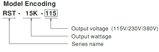
- Model Encoding

SPECIFICATION
| MODEL | RST-15K-115 | RST-15K-230 | RST-15K-380 | |
| OUTPUT | DC VOLTAGE (factory default) | 115V | 230V | 380V |
| CURRENT (factory default) | 130A | 64.8A | 39.55A | |
| CURRENT RANGE | 0 ~ 130A | 0 ~ 69A | 0 ~ 45A | |
| RATED POWER | 14950W | 14904W | 15030W | |
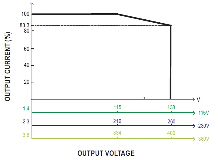
| FULL POWER VOLTAGE RANGE | 115 ~ 138V | 216 ~ 260V | 334 ~ 400V | |
| RIPPLE & NOISE (max.) Note.2 | 1Vp-p | 2Vp-p | 4Vp-p | |
| VOLTAGE ADJ. RANGE | 90 ~ 138V | 170 ~ 260V | 260 ~ 400V | |
| Can be adjusted via built-in potentiometer | ||||
| VOLTAGE TOLERANCE Note.3 | ±1.0% | ±1.0% | ±1.0% | |
| LINE REGULATION | ±0.5% | ±0.5% | ±0.5% | |
| LOAD REGULATION | ±0.5% | ±0.5% | ±0.5% | |
| SETUP, RISE TIME | 3000ms, 200ms at full load | |||
| HOLD UP TIME (Typ.) | 16ms 230VAC/400VAC at 75% load 10ms / 230VAC/400VAC at full load | |||
| INPUT | VOLTAGE RANGE | 3ψ 3W/△196~305VAC or 3ψ 4W/Y 340~530VAC | ||
| FREQUENCY RANGE | 47 ~ 63Hz | |||
| POWER FACTOR (Typ.) | ≧0.98/230VAC(400VAC)/≧0.97/277VAC(480VAC) at full load | |||
| EFFICIENCY (Typ.) Note.7 | 93% | 94% | 94% | |
| AC CURRENT (Typ.) | 45A/230VAC(3ψ 3-wire / △) 26A/230VAC(3ψ 4-wire / Y) | |||
| INRUSH CURRENT (Typ.) | 150A/230VAC(3ψ 3-wire / △) 100A/230VAC(3ψ 4-wire / Y) | |||
| LEAKAGE CURRENT | <3.5mA/Y 530VAC <21mA /△305VAC | |||
| PROTECTION | OVERLOAD | 100 ~ 107% of rated current | ||
| Protection type : Constant current limiting, unit will shutdown after 5 sec. re-power on to recover | ||||
| OVER VOLTAGE | 145 ~ 166V | 273 ~ 312V | 420 ~ 480V | |
| Protection type : Shut down o/p voltage, re-power on to recover | ||||
| OVER TEMPERATURE | Shut down o/p voltage, recovers automatically after temperature goes down | |||
| FUNCTION | CURRENT SHARING | Up to 2 units. Please refer to the Function Manual | ||
| OUTPUT VOLTAGE PROGRAMMABLE | Adjustment of output voltage is allowable between 1 ~ 120% of nominal output voltage. Please refer to the PV curve Function Manual | |||
| CONSTANT CURRENT LEVEL PROGRAMMABLE | Adjustment of constant current level is allowable between 20 ~ 100% of rated current. Please refer to the Function Manual | |||
| REMOTE ON-OFF CONTROL | Please refer to the Function Manual | |||
| ALARM SIGNAL OUTPUT | AC fail, DC OK, fan fail, OTP. Please refer to the Function Manual. | |||
| ENVIRONMENT | WORKING TEMP. | -30 ~ +70℃ (Refer to “Derating Curve”) | ||
| WORKING HUMIDITY | 20 ~ 90% RH non-condensing | |||
| STORAGE TEMP., HUMIDITY | -40 ~ +85℃, 10 ~ 95% RH non-condensing | |||
| TEMP. COEFFICIENT | ±0.03%/℃ (0 ~ 45℃) | |||
| VIBRATION | 10 ~ 500Hz, 2G 10min./1cycle, 60min. each along X, Y, Z axes | |||
| SAFETY & EMC (Note 6,8) | SAFETY STANDARDS | UL62368-1, CAN/CSA C22.2 No. 62368-1, TUV BS EN/EN62368-1, EAC TP TC 004 approved | ||
| WITHSTAND VOLTAGE | I/P-O/P:4.3KVDC I/P-FG:2.8KVDC O/P-FG:2.8KVDC | |||
| ISOLATION RESISTANCE | I/P-O/P, I/P-FG, O/P-FG:100M Ohms / 500VDC / 25℃/ 70% RH | |||
| EMC EMISSION | Parameter | Standard | Test Level / Note | |
| Conducted | BS EN/EN55032 (CISPR32) / BS EN/EN55011 (CISPR11) | Class B | ||
| Radiated | BS EN/EN55032 (CISPR32) / BS EN/EN55011 (CISPR11) | Class A | ||
| Harmonic Current | BS EN/EN61000-3-12 | —– | ||
| Voltage Flicker | BS EN/EN61000-3-3 | —– | ||
| EMC IMMUNITY | BS EN/EN55024 , BS EN/EN61204-3, BS EN/EN61000-6-2 | |||
| Parameter | Standard | Test Level / Note | ||
| ESD | BS EN/EN61000-4-2 | Level 3, 8KV air ; Level 2, 4KV contact | ||
| Radiated | BS EN/EN61000-4-3 | Level 3 | ||
| EFT / Burst | BS EN/EN61000-4-4 | Level 3 | ||
| Surge | BS EN/EN61000-4-5 | Level 4, 4KV/Line-Earth ; Level 3, 2KV/Line-Line | ||
| Conducted | BS EN/EN61000-4-6 | Level 3 | ||
| Magnetic Field | BS EN/EN61000-4-8 | Level 4 | ||
| Voltage Dips and Interruptions | BS EN/EN61000-4-11 | >95% dip 0.5 periods, 30% dip 25 periods, >95% interruptions 250 periods | ||
| OTHERS | MTBF | 121.9K hrs min. Telcordia SR-332 (Bellcore) ; 16.2K hrs min. MIL-HDBK-217F (25℃) | ||
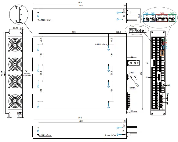
| DIMENSION | 540*424*83.5mm (L*W*H) | |||
| PACKING | 25Kg; 1pcs/25Kg/2.82CUFT | |||
| NOTE |
| |||
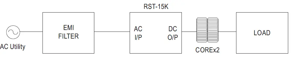
Block Diagram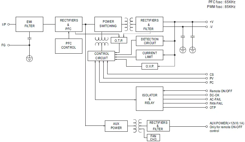 DERATING CURVE
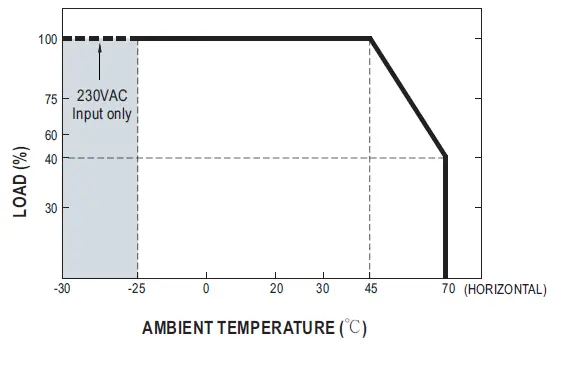
STATIC CHARACTERISTICS EFFICIENCY VS LOAD (380V MODEL)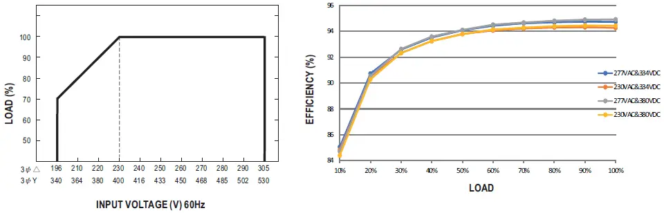
AC Power Connection
Fig 1.2
◎3ψ3-wire /△196~305VAC 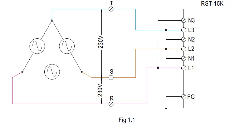 ψ 3 4-wire / Y 340~530VAC
 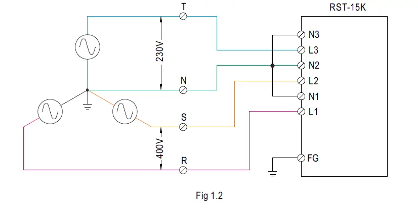 Note : RST-15K can also be operated by 1ψ2-wire 196~305VAC input. Please refer to the connection diagram below.
Operating with 1ψ2-wire may lead to certain characteristics different from the specification, such as the larger Ripple and Noise. Should there be any issues, please contact MEAN WELL. 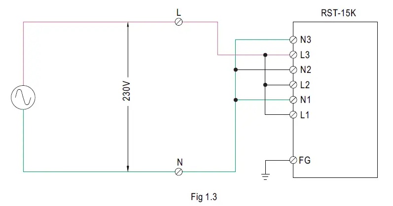
Function Manual
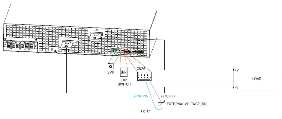
- Output Voltage Programming (or, PV / remote voltage programming / remote adjust / margin programming / dynamic voltage trim)
- Default by potentiometer (SVR)
- Have the DIP switch position-3 set as
- Output voltage can be trimmed by SVR.
- By Output Voltage Programming
- Have the DIP switch position-3 set as
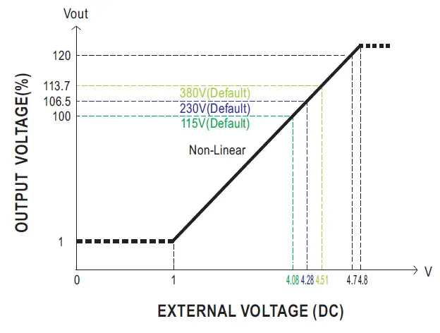
- The output voltage can be trimmed to 1~120% by applying EXTERNAL VOLTAGE between PV+ and PV- on CN26 or CN27.


- The 100% output voltage is 115/216/334V.
- When PV signal to adjust voltage under Vo<11.5V(115V model) / 21.6V(230V model) / 33.4V(380V model) with dynamic load condition, the Vo overshoot & undershoot might go over rating.

- The rated current should change with the Output Voltage Programming accordingly.
- Maximum output current is Based on rated power wattage.
- Default by potentiometer (SVR)
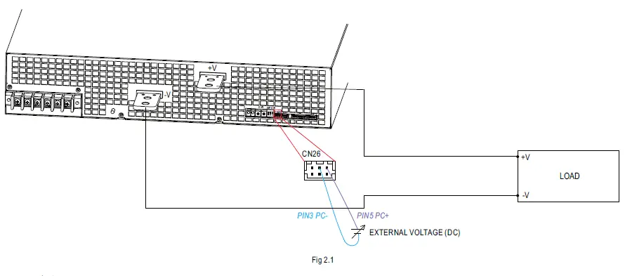
- Constant Current Programming (or, PC / remote current programming / dynamic current trim)
- Default Overload Protection(OLP) 100~107% of rated current
- Have the DIP switch position-2 set as
- Output current is set default value.
- by Constant Current Level Programming
- Have the DIP switch position-2 set as
- The constant current level can be trimmed to 20~100% of the rated current by applying EXTERNAL VOLTAGE between PC+ and PC- on CN26 or CN27.
- Default Overload Protection(OLP) 100~107% of rated current
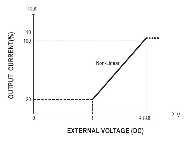 EXTERNAL VOLTAGE (DC)
Fig 2.2
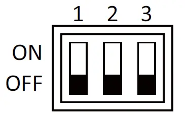
3. Select Overload Protection (OLP) Mode
(1) Default Continuous Constant Current mode
Have the DIPswitch position-1 set as ,and RST-15K will work in continuous constant current mode when the output is overloaded andthe output voltage is greater than 50% of the rated output voltage.
Delay Shutdown mode
Have the DIPswitch position-1 set as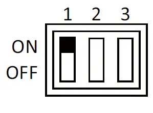 ,and RST-15K will shut down after 5 seconds of constant current operation, when the output is overloaded or short-circuited.
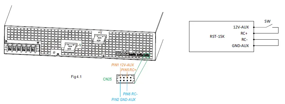
Remote ON-OFF Control
- The power supply can be turned ON-OFF by using the “Remote ON-OFF” function.
Between Remote ON-OFF(CN25 pin5) and 12V-AUX(CN25 pin1) Output Status Switch close (Short) power supply ON Switch open (Open) power supply OFF Table 4.1
 5. Alarm Signal Output
※ There are 4 alarm signals on CN22, and each signal can select two types of output circuit.
(1)Relay contact output {OTP1, OTP1-GND) ; (DC-OK1, DC-OK1-GND) ; (AC-FAIL1-GND, AC-FAIL1) ; (FAN-FAIL1-GND, FAN-FAIL1)} Normally open contact. “Short” when the alarm arises. Relay contact rating(maximum) is 30V/1A resistive.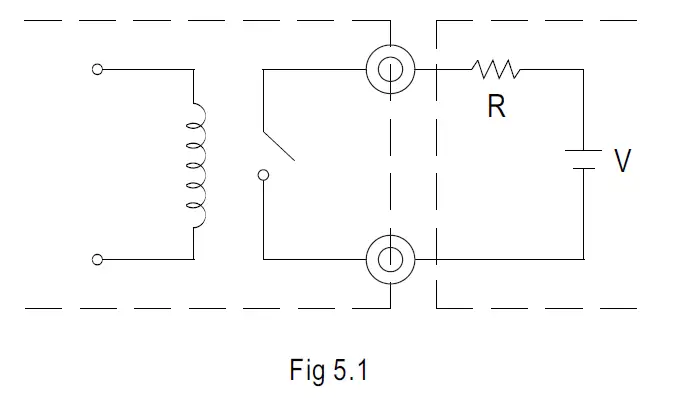 (2)Open collector output {DC-OK2-GND, DC-OK2) ; (AC-FAIL2-GND, AC-FAIL2) ; (OTP2, OTP2-GND) ; (FAN-FAIL2, FAN-FAIL2-GND)} An external voltage source is required for this function that is shown in Fig 5.2. These signals are isolated from output. The maximum sink current is 10mA and the maximum external voltage is 20V (there is a built-in 24V zener diode in inner circuitry).
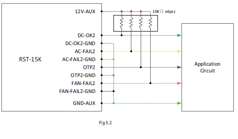 6. Current Sharing
RST-15K has the built-in active current sharing function and can be connected in parallel, up to 2 units, to provide higher output power as exhibited below :
※ The voltage difference among each output should be minimized that less than 0.2V is required.
※ The total output current must not exceed the value determined by the following equation.
Maximum output current at parallel operation=(The rated current per unit)x(Number of unit)x0.95
※ When the total output current is less than 5% of the total rated current, or say (5% of Rated current per unit)×(Number of unit)
the current shared among units may not be fully balanced. 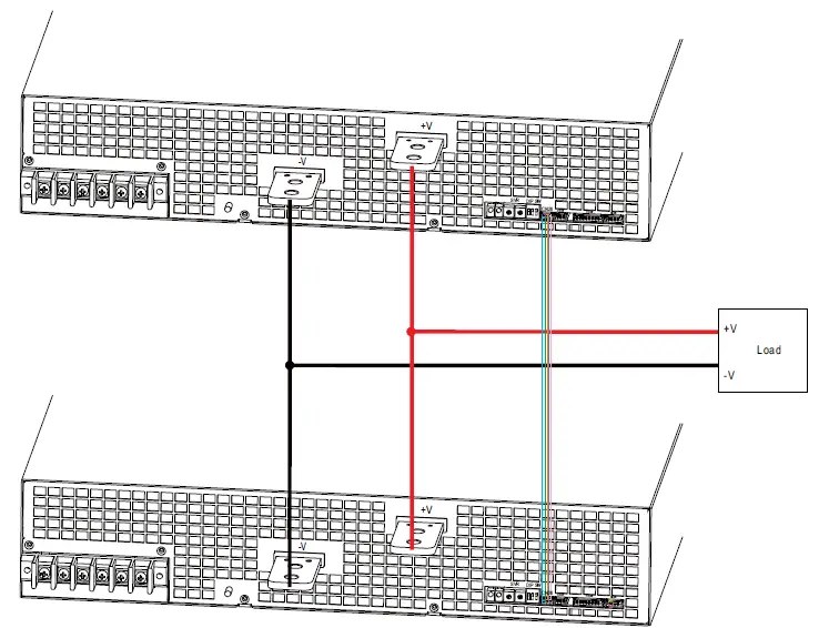 CS+, CS- and RC+, RC- are connected mutually in parallel.
Mechanical Specification
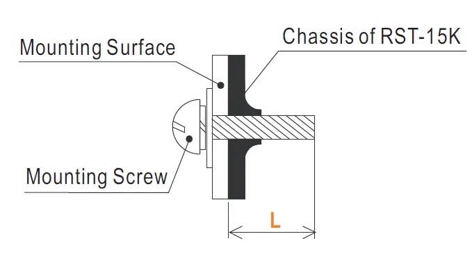
 Mounting Instruction
| Hole No. | Recommended Screw Size | MAX. Penetration Depth L | Recommended mounting torque |
| 1 | M4 | 5mm | 7~10Kgf-cm |
 Control Pin No. Assignment CN26,CN27(): HRS DF11-06DP-2DS or equivalent 15
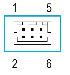
| Mating Housing | HRS DF11-06DS or equivalent |
| Terminal | HRS DF11-**SC or equivalent |
CN26 and CN27 are connected internally.
| Pin No. | Function | Description |
| 1 | CS- | Current sharing signal. When units are connected in parallel, the CS pins of the units should be connected to allow current balance between units. |
| 2 | CS+ | |
| 3 | PC- | Connection for output current programming. |
| 4 | PV- | Connection for output voltage programming. |
| 5 | PC+ | Connection for output current programming. |
| 6 | PV+ | Connection for output voltage programming. |
Control Pin No. Assignment CN22(): HRS DF11-16DP-2DS or equivalent 1 15
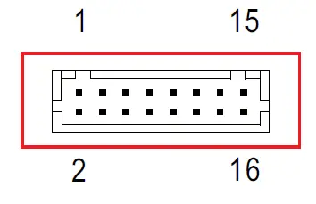
| Mating Housing | HRS DF11-16DS or equivalent |
| Terminal | HRS DF11-**SC or equivalent |
| Pin No. | Function | Description |
| 1 | DC-OK1 | Alarm signal of DC-OK. Normally open contact. “Short” when the PSU turns on. Relay contact rating(maximum) is 30V/1A resistive. |
| 2 | AC-FAIL1 | Alarm signal of AC-fail. Normally open contact. “Short” when the PSU input voltage is too low. Relay contact rating(maximum) is 30V/1A resistive. |
| 3 | DC-OK1-GND | Alarm signal of DC-OK. Normally open contact. “Short” when the PSU turns on. Relay contact rating(maximum) is 30V/1A resistive. |
| 4 | AC-FAIL1-GND | Alarm signal of AC-fail. Normally open contact. “Short” when the PSU input voltage is too low. Relay contact rating(maximum) is 30V/1A resistive. |
| 5 | DC-OK2 | Alarm signal of DC-OK. Open collector signal. Low when the PSU turns on. The maximum sink current is 10mA and the maximum external voltage is 20V. |
| 6 | AC-FAIL2 | Alarm signal of AC fail. Open collector signal. Low when the PSU input voltage is too low. The maximum sink current is 10mA and the maximum external voltage is 20V. |
| 7 | DC-OK2-GND | Alarm signal of DC-OK. Open collector signal. Low when the PSU turns on. The maximum sink current is 10mA and the maximum external voltage is 20V. |
| 8 | AC-FAIL2-GND | Alarm signal of AC fail. Open collector signal. Low when the PSU input voltage is too low. The maximum sink current is 10mA and the maximum external voltage is 20V. |
| 9 | OTP1 | Alarm signal of OTP. Normally open contact. “Short” when the PSU over temperature protection occurs. Relay contact rating(maximum) is 30V/1A resistive. |
| 10 | FAN-FAIL2 | Alarm signal of fan fail. Open collector signal. Low when the internal fan fails. The maximum sink current is 10mA and the maximum external voltage is 20V. |
| 11 | OTP1-GND | Alarm signal of OTP. Normally open contact. “Short” when the PSU over temperature protection occurs. Relay contact rating(maximum) is 30V/1A resistive. |
| 12 | FAN-FAIL2-GND | Alarm signal of fan fail. Open collector signal. Low when the internal fan fails. The maximum sink current is 10mA and the maximum external voltage is 20V. |
| 13 | OTP2 | Alarm signal of OTP. Open collector signal. Low when the PSU over temperature protection occurs. The maximum sink current is 10mA and the maximum external voltage is 20V. |
| 14 | FAN-FAIL1 | Alarm signal of fan fail. Normally open contact. “Short” when the internal fan fails. Relay contact rating(maximum) is 30V/1A resistive. |
| 15 | OTP2-GND | Alarm signal of OTP. Open collector signal. Low when the PSU over temperature protection occurs. The maximum sink current is 10mA and the maximum external voltage is 20V. |
| 16 | FAN-FAIL1-GND | Alarm signal of fan fail. Normally open contact. “Short” when the internal fan fails. Relay contact rating(maximum) is 30V/1A resistive. |
Control Pin No. Assignment (CN25) : HRS DF11-08DP-2DS or equivalent 1 7
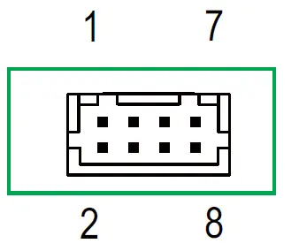
| Mating Housing | HRS DF11-08DS or equivalent |
| Terminal | HRS DF11-**SC or equivalent |
| Pin No. | Function | Description |
| 1,3 | 12V-AUX | Auxiliary voltage output, 11.4~12.6V, referenced to pin 2,4(GND-AUX). Only for remote on-off control & Alarm signal. The maximum load current is 0.1A. This output is not controlled by the “Remote ON/OFF” function. |
| 2,4 | GND-AUX | Auxiliary voltage output GND. The signal return is isolated from the output terminals (+V & -V). |
| 5,7 | RC+ |
The output can be turned ON-OFF in association with RC+ and RC-. |
| 6,8 | RC- |
References
 TÜV Rheinland - Home | US | TÜV Rheinland
 MEAN WELL Switching Power Supply Manufacturer
-
Installation Manual-MEAN WELL Switching Power Supply Manufacturer
-
Product Liability Disclaimer-MEAN WELL Switching Power Supply Manufacturer
-
Global Trade Item Number (GTIN)-MEAN WELL Switching Power Supply Manufacturer


