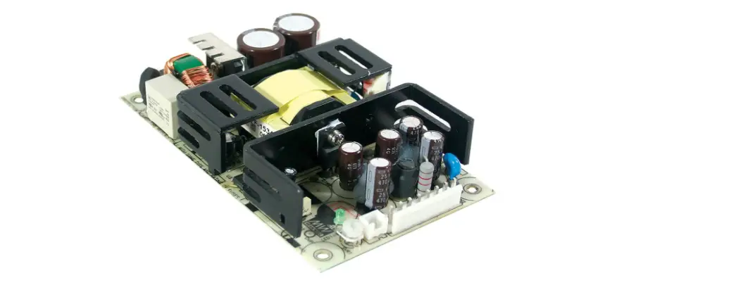
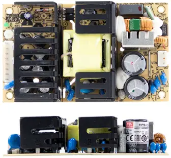
MEAN WELL RPD-75 Series 75W Dual Output Medical Grade
Features
- 5×3 compact size
- Medical safety approved (2 x MOPP) according to ANSI/AAMI ES60601-1 and IEC/BS EN/EN60601-1
- Suitable for BF application with appropriate system consideration.
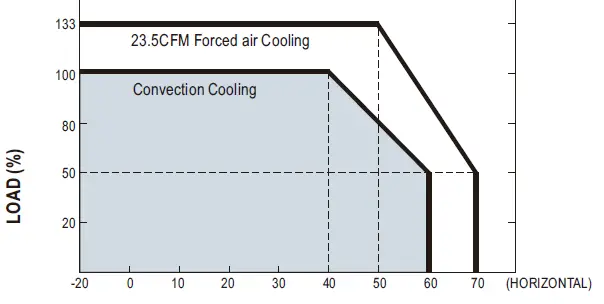
- Free air convection for rated power and 23.5CFM forced air convection for peak load.
- EMI class B for class Ⅰ configuration.
- Extremely low leakage current.
- Protections: Short circuit / Overload / Over voltage
- Lifetime > 140K hours
- 3 years warranty.
Applications
- Oral irrigator
- Hemodialysis machine
- Medical computer monitors
- Sleep apnea devices
GTIN CODE
MW Search: https://www.meanwell.comiserice GTIN asp
Description
RPD-75 is a 75W highly reliable green PCB type medical power supply with a high power density on the 5 by 3 footprint. It accepts 90~264VAC input and offers dual output voltages. RPD-75 is able to be used for Class Ⅰ with FG system design. The extremely low leakage current is less than 150 μA. In addition, it conforms to international medical regulations (2 MOPP) and EMC BS EN/EN55011.
Model Encoding
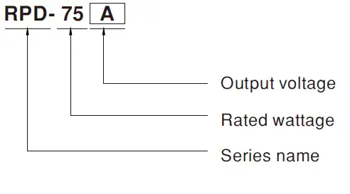
75 Reliable Dual Output Medical Grade
| MODEL | RPD-75A | RPD-75B | |||||
|
OUTPUT | OUTPUT NUMBER | CH1 | CH2 | CH1 | CH2 | ||
| DC VOLTAGE | 5V | 12V | 5V | 24V | |||
| RATED CURRENT | 7A | 3A | 5A | 2A | |||
| CURRENT RANGE | 1 ~ 9.5A | 0.3 ~ 4A | 1 ~ 6.8A | 0.2 ~ 2.7A | |||
| RATED POWER | 71W | 73W | |||||
| PEAK LOAD (23.5CFM) | 95.5W | 98.8W | |||||
| RIPPLE & NOISE max Note.2 | 80mVp-p | 120mVp-p | 80mVp-p | 120mVp-p | |||
| VOLTAGE ADJ. RANGE | CH1: 4.75 ~ 5.5V | CH1: 4.75 ~ 5.5V | |||||
| VOLTAGE TOLERANCE Note.3 | ±2.0% | ±6.0% | ±2.0% | ±6.0% | |||
| LINE REGULATION | ±0.5% | ±1.0% | ±0.5% | ±1.0% | |||
| LOAD REGULATION | ±1.5% | ±3.0% | ±1.5% | ±3.0% | |||
| SETUP, RISE TIME | 500ms, 30ms/230VAC 500ms, 30ms/115VAC at full load | ||||||
| HOLD UP TIME (Typ.) | 90ms/230VAC 20ms/115VAC at full load | ||||||
|
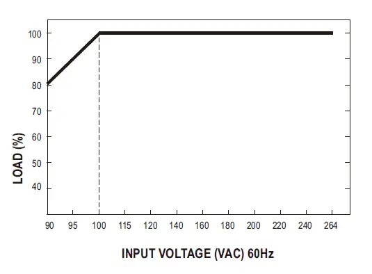
INPUT | VOLTAGE RANGE | 90 ~ 264VAC 127 ~ 370VDC | |||||
| FREQUENCY RANGE | 47 ~ 63Hz | ||||||
| EFFICIENCY (Typ.) | 77% | 79% | |||||
| AC CURRENT (Typ.) | 1.5A/115VAC 1A/230VAC | ||||||
| INRUSH CURRENT (Typ.) | COLD START 25A/115VAC 50A/230VAC | ||||||
| LEAKAGE CURRENT Note.4 | Earth leakage current < 150μA/264VAC , Touch current < 100μA/264VAC | ||||||
| PROTECTION | OVERLOAD | 140 ~ 180% rated output power | |||||
| Protection type : Hiccup mode, recovers automatically after fault condition is removed | |||||||
| OVER VOLTAGE | Ch1: 5.7 ~ 6.8V | ||||||
| Protection type : Shut down o/p voltage, re-power on to recover | |||||||
|
ENVIRONMENT | WORKING TEMP. | -20 ~ +70℃ (Refer to “Derating Curve”) | |||||
| WORKING HUMIDITY | 20 ~ 90% RH non-condensing | ||||||
| STORAGE TEMP., HUMIDITY | -40 ~ +85℃, 10 ~ 95% RH non-condensing | ||||||
| TEMP. COEFFICIENT | ±0.03%/℃ (0 ~ 50℃) | ||||||
| VIBRATION | 10 ~ 500Hz, 2G 10min./1cycle, period for 60min. each along X, Y, Z axes | ||||||
| OPERATING ALTITUDE Note.5 | 3000 meters | ||||||
|
SAFETY & EMC (Note 8) | SAFETY STANDARDS | IEC60601-1, EAC TP TC 004, UL ANSI/AAMI ES60601-1, CAN/CSA-C22.2 No. 60601-1:14 – Edition 3 approved, TUV BS EN/EN60601-1 approved | |||||
| ISOLATION LEVEL | Primary-Secondary:2xMOPP, Primary-Earth:1xMOPP | ||||||
| WITHSTAND VOLTAGE | I/P-O/P:4KVAC I/P-FG:2KVAC O/P-FG:1.5KVAC | ||||||
| ISOLATION RESISTANCE | I/P-O/P, I/P-FG, O/P-FG:100M Ohms / 500VDC / 25℃/ 70% RH | ||||||
| EMC EMISSION | Parameter | Standard | Test Level / Note | ||||
| Conducted emission | BS EN/EN55011 (CISPR11) | Class B | |||||
| Radiated emission | BS EN/EN55011 (CISPR11) | Class B | |||||
| Harmonic current | BS EN/EN61000-3-2 | Class A | |||||
| Voltage flicker | BS EN/EN61000-3-3 | —– | |||||
|
EMC IMMUNITY | BS EN/EN60601-1-2 | ||||||
| Parameter | Standard | Test Level / Note | |||||
| ESD | BS EN/EN61000-4-2 | Level 4, 15KV air ; Level 4, 8KV contact | |||||
| RF field susceptibility | BS EN/EN61000-4-3 | Level 3, 10V/m 80MHz~2.7GHz Table 9, 9~28V/m 385MHz~5.78GHz | |||||
| EFT bursts | BS EN/EN61000-4-4 | Level 3, 2KV | |||||
| Surge susceptibility | BS EN/EN61000-4-5 | Level 4, 4KV/Line-FG ; 2KV/Line-Line | |||||
| Conducted susceptibility | BS EN/EN61000-4-6 | Level 3, 10V | |||||
| Magnetic field immunity | BS EN/EN61000-4-8 | Level 4, 30A/m | |||||
| Voltage dip, interruption | BS EN/EN61000-4-11 | 100% dip 1 periods, 30% dip 25 periods, 100% interruptions 250 periods | |||||
| OTHERS | MTBF | 2575.6K hrs min. Telcordia SR-332 (Bellcore) ; 569.9K hrs min. MIL-HDBK-217F (25℃) | |||||
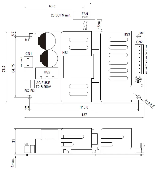
| DIMENSION L WH | 127*76.2*31mm or 5 31.22 nch | ||||||
| PACKING | 0.25Kg; 63pcs/17.3Kg/1.28CUFT | ||||||
| NOTE
| All parameters NOT specially mentioned are measured at 230VAC input, rated load and 25 of ambient temperature. Ripple & noise are measured at 20MHz of bandwidth by using a 12 twisted pair-wire terminated with a 0.1af & 47uf parallel capacitor. Tolerance: includes set up tolerance, line regulation and load regulation. Touch Current was measured from primary input to DC output. The ambient temperature derating of 3.5 C/1000m with fan less models and of 5 C/1000m with fan models for operating altitude higher than 2000m(6500ft) Length of set up time is measured at cold first start. Turning ONOFF the power supply may lead to increase of the set up time.Heat Sik HS1,HS2,HS3 can not be shorted. The power supply is considered a component which will be installed into a final equipment. All the EMC tests are been executed by mounting the unit on a 360mm*360mm metal plate with 1mm of thickness. The final equipment must be re-confirmed that it still meets EMC directives. For guidance on how to perform these EMC tests, please refer to “EMI testing of component power supplies as avalilable on http://www.meanwell.com X Product Liability Disclaimer: For detailed information. please refer to https://www.meanwell.com/service Disclaimer.asp | ||||||
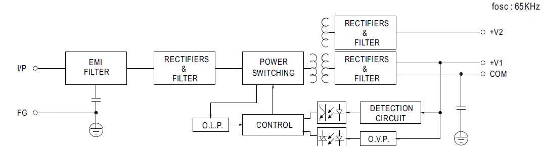
Block Diagram
Derating Curve
Output Derating VS Input Voltage
Mechanical Specification
Front and Side View
 AC Input Connector CN1 : JST B3P-VH or equivalent
 AC Input Connector CN1 : JST B3P-VH or equivalent
| Pin No. | Assignment | Mating Housing | Terminal |
| 1 | AC/N | JST VHR or equivalent | JST SVH-21T-P1.1 or equivalent |
| 2 | No Pin | ||
| 3 | AC/L |
DC Output Connector (CN2) : JST B8P-VH or equivalent
| Pin No. | Assignment | Mating Housing | Terminal |
| 1,2 | V1 | JST VHR or equivalent | JST SVH-21T-P1.1 or equivalent |
| 3,4,5 | COM | ||
| 6,7 | V2 | ||
| 8 | NC |
Grounding Required
HS1,HS2,HS3 cannot be shorted. M1 is safety ground. For better EMC performance. Please secure an electrical connection between M1,M2 and chassis grounding.
M 1 M2 Installation Manual Please refer to : http://www.meanwell.com/manual.html


