![]() Operating Instructions
Operating Instructions
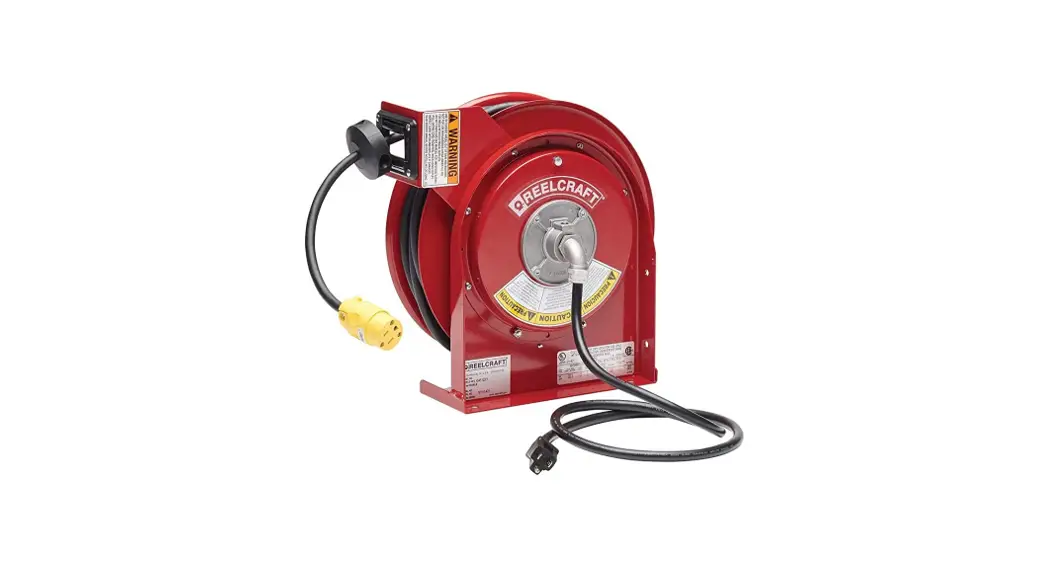
Series L 3000 Spring Driven Cord Reels
L 3030 123 3 L 3030 123 7 L 3030 123 7Q L 3030 123 X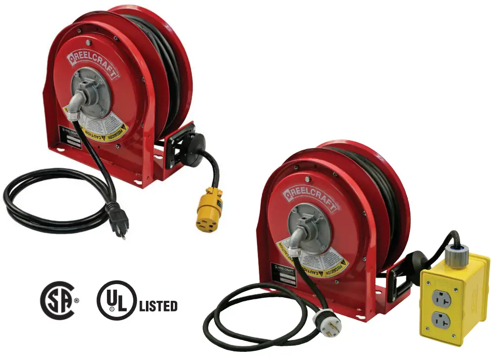
L 3000 Series Spring Driven Cord Reels
IMPORTANT
Read this manual carefully before installing, operating or servicing this equipment.
Dimensions
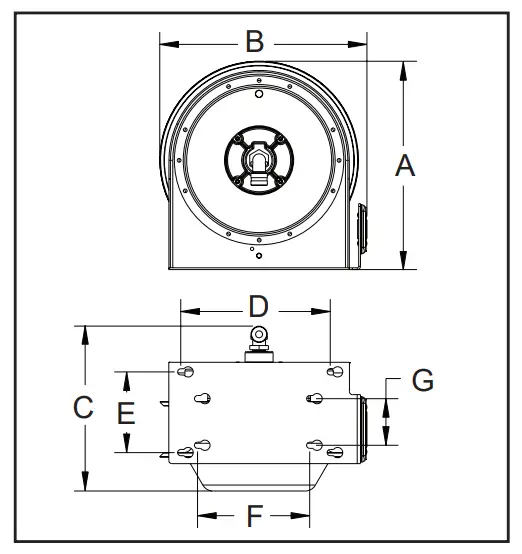
| A | 11 3/16” |
| B | 11 1/16” |
| C | 9 1/4” |
| D | 8” |
| E | 4 3/16” |
| F | 6” |
| G | 2 1/2” |
Safety Precautions
Personal injury and / or equipment damage may result if proper safety precautions are not observed.
- Ensure that only a qualified electrician installs / services this equipment.
- Ensure that power supply voltage does not exceed maximum voltage rating of reel.
- Ensure that reel is properly installed before connecting to power supply.
- All cord reels with flying leads must be hard wired to ensure proper function.
- Ensure that all electrical power is removed from reel before servicing.
- A high-tension spring assembly is contained within the reel. Exercise extreme caution.
Optional Guide Arm Dimensions
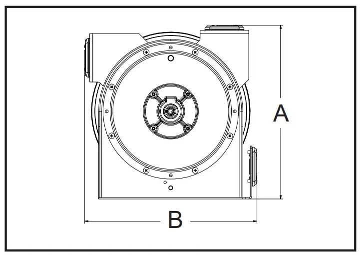
| A | 11 5/8” |
| B | 11 9/16” |
WARNING: Even low voltage can cause irreparable damage or death! Exercise extreme caution while operating or servicing this equipment.
- Check for frayed and/or broken wires before each use. Pull electrical cord from reel by grasping the electrical cord itself, not the work device.
- If an electrical malfunction should occur, remove power from reel immediately.
- Ensure that reel, electrical cord, and equipment being serviced are properly grounded. Use an ohmmeter to check ground continuity.
- If reel ceases to unwind or rewind, remove power immediately. Do not pull or jerk on electrical cord!
- Treat and respect the reel as any other piece of machinery, observing all common safety practices.
Installation Instructions
Mounting
CAUTION: Unless reel was specified differently when ordering, maximum installation height is 16 feet. Do not exceed this distance. Ensure that only a qualified electrician installs/ services this equipment. Installation of GFCI cord reels should be performed by a qualified and licensed professional in accordance with building codes and applicable NEC standards.
- Unpack and inspect reel for damage. Turn by hand to check for smooth operation.
- Standard configuration of reel is bottom wind. For top or side wind electrical cord dispensing you will need guide arm accessory kit (sold separately). Install by removing two nuts and bolts (1) and (2), that are securing the spring case. Determine new guide arm location. Position guide arm bracket to reel and replace bolts.
- Position reel under workbench, on floor, wall, or ceiling.
Secure into place, using four (customer supplied) screws or bolts (3).
Service Instructions
Maintain reel by following the service instructions given below.
Refer all other repairs, other than those listed, only to an authorized service person or directly to Reelcraft. Failure to do so can result in personal injury and/or equipment damage and may void the warranty (refer to page 4 when referencing parts).
WARNING: Remove power from reel before performing any of the following procedures.
Adjustments – Spring Tension
If necessary, adjust spring tension on reel by adding or removing wraps of electrical cord from spool, one wrap at a time, until desired tension is obtained. Add wraps to increase tension. Remove wraps to decrease tension.
WARNING: When adding wraps of electrical cord, be careful not to exceed the winding mechanism’s spring capacity. Add just enough wraps of cord to achieve the desired tension. Damage to the winding mechanism will result if spring is overtensioned. Always be aware of spring tension on reel. Exercise extreme caution. Refer to online tech bulletin.
Troubleshooting Instructions
Troubleshooting of the reel consists of isolating a problem to a defective electrical cord/work device, brush holder/brushes, or collector assembly. Refer any other discrepancies only to an authorized service person or directly to Reelcraft.
WARNING: The following procedure directs the technician to take voltage measurements. Remember, even low voltage is dangerous and can cause personal injury or death. Exercise extreme caution! Ensure that only a qualified electrician installs / services this equipment.
- If work device is an electrical receptacle, ensure that tool or fixture connected to it is in good working order. If it is, proceed to step 2.
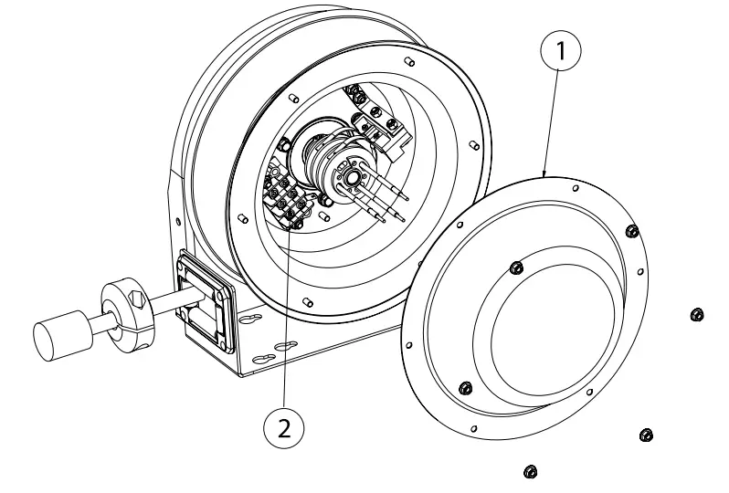
- Remove power from reel.
- Remove access cover (1).
- Reapply power to reel.
- Check for correct voltage (120 V AC) at terminal strip (2).
If voltage reading is correct, replace output electrical cord / device. If voltage reading is incorrect, proceed to step 6. - Remove power from reel.
- Using ohmmeter, check continuity of input electrical cord.
If cord checks good, proceed to step 8. If cord is faulty, replace it. - Remove brush holder / brushes from reel and inspect.
Replace defective components then proceed to step 9. - Reapply power to reel.
- Check for correct voltage (120 V AC) at terminal strip (2). If voltage reading is still incorrect, replace defective collector assembly.
- Replace access cover (1).
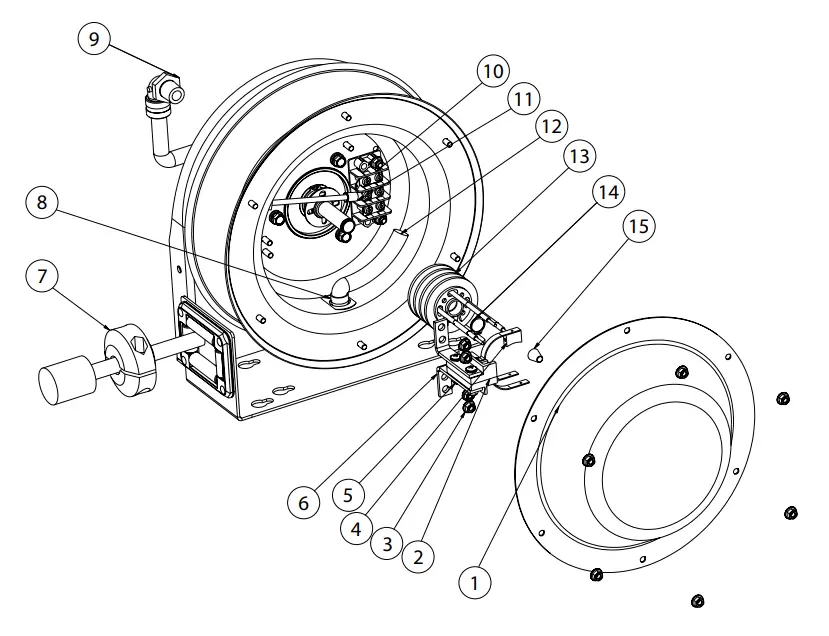
Replacing the Output Electrical Cord/Work Device
WARNING: Use extreme caution, reel under tension. Avoid releasing latch mechanism.
- Pull output electrical cord from reel until fully extended, then latch.
- Remove output electrical bumper stop (7).
- Disconnect output electrical cord / work device (12) at terminal strip (10).
- Remove strain relief (8). Remove output electrical cord / work device.
- Install replacement electrical cord / work device by reversing steps 2 through 4.
- Release latch and rewind electrical cord on reel.
- Replace access cover (1).
Replacing the Input Electrical Cord
- Remove wire nuts (15) securing input electrical cord to collector assembly (13).
- Remove 90 degree elbow (9).
- Remove input electrical cord.
- Remove 11” of outer jacket from replacement input electrical cord (input electrical cord wires must protrude a minimum of 6” from center of collector assembly).
- Install replacement input electrical cord by reversing steps 1 through 3.
- Replace access cover (1).
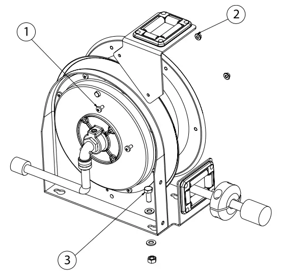
Replacing the Brush Holder/Brushes
- At terminal strip (10), remove wires connecting brushes (11) to terminal strip.
- Remove lock nuts (3) securing brush holder (6) to reel.
Relocate cable clamp temporarily and remove brush holder. - Remove brushes (4) from brush holder (6).
- Install replacement brush holder / brushes by reversing steps 1 through 3. Upon completion of installation, adjust brush-to-ring alignment by loosening nuts (5) and sliding finger assembly (2).
Replacing the Collector Assembly
- Remove wire nuts (15) securing input electrical cord to collector assembly.
- At terminal strip (10), disconnect wires (11) connecting brushes (4) to terminal strip.
- Remove lock nuts (3) securing brush holder (6) to reel.
Relocate cable clamp temporarily and remove brush holder. - Remove snap ring (14).
- Remove collector assembly (13).
- Install replacement collector assembly by reversing steps 1 through 5. Upon completion of installation, adjust brush- to-ring alignment by loosening nuts (5) and sliding finger assembly (2).
- Replace access cover (1).
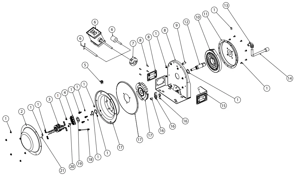
| Item # | Description | # Req. | Part # |
| 1 | Hardware assembly | 1 | S602810 |
| Flex lock nut M5 | 20 | ||
| Snap ring | 1 | ||
| Flex washer screw | 3 | ||
| Flat washer | 3 | ||
| Lock washer | 3 | ||
| Screw set 3/8-16 x 1/2″ | 1 | ||
| Machine screw M5 x 10 | 8 | ||
| Spacing washer 1.005″ ID x 1.312″ OD x.020″ THK | 2 | ||
| Snap ring | 1 | ||
| 2 | Cover, slip ring | 1 | S263152 |
| 3 | Slip ring and brush assy | 1 | 602296 |
| 4 | Terminal block | 1 | 600205 |
| 5 | Cord clamp | 1 | 260633 |
| 6 | Cord and outlet assembly | 1 | See below |
| 7 | Bumper assembly | 2 | 1-HR1004-A |
| 8 | Base and spring assembly | 1 | S602808 |
| Tube rivet | 4 | ||
| Universal roller (21 | 1 | ||
| Base weldment assembly | 1 | ||
| 9 | Spring case stud | 1 | 261360 |
| 10 | Drive spring assembly | 1 | 400030 |
| 11 | Spring case assembly | 1 | 400103 |
| 12 | Main shaft with snap ring | 1 | 602348 |
| 13 | Connector 90 degree | 1 | 261140-C |
| 14 | Cord inlet 5-15 SP, 2-POLE, 3-WIRE grounding | 1 | 260630 |
| 15 | Guide arm assembly w/hardware (sold separately) | 1 | S602805 |
| 16 | Latch pawl assembly | 1 | S602809 |
| Torsion spring | 1 | ||
| Latch pawl | 1 | ||
| Latch pin | 1 | ||
| 17 | Sheave assembly | 1 | S602811 |
| Arbor, ratchet | 1 | ||
| Sheave disc | 1 | ||
| Sheave flange and studs assembly | 1 | ||
| 18 | Cord assembly (grounding) | 1 | 600283 |
| 19 | Adapter plate | 1 | 261577 |
| 20 | Connector | 1 | 260609 |
| 21 | Nut, wire (AWG 12-10, WN4, YELLOW) | 3 | 260774 |
| Item # | Description | # Req. | L 3030 123 3 | L 3030 123 7 | L 3030 123 7Q | L 3030 123 X |
| 6 | Cord and outlet assembly | 1 | S602812-30 | Coming Soon | S602813-30 | S602353-30 |
| Cord size and length | 12 /3 x 30′ | 12/3×30′ | 12 /3 x30′ | 12 /3 x 30′ | ||
| Cord ending | Single Receptacle | Duplex Box | Quad Box | Flying Lead | ||
| Volts | 125 | 125 | 125 | 125 | ||
| Amps | 15 | 15 | 20 | 20 | ||
| Cord Type | SJTO | SJTO | SJTO | SJTO | ||
Reelcraft Industries, Inc.
2842 E Business Hwy 30, Columbia City, IN 46725
Ph: 800-444-3134 / 260-248-8188
Fax: 800-444-4587 / 260-248-2605
Customer Service: 855-634-9109
[email protected]
www.reelcraft.com
www.reelcraft.com


