![]()
ADI Power by Linear™
DEMO MANUAL
EVAL-LT8357-AZ
LT8357
60V Low IQ Boost Controller
DESCRIPTION
Evaluation circuit EVAL-LT8357-AZ features the LT ® 8357as a 200kHz low EMI and low IQ, boost controller with a 24V output from 4.5V to 20V input. This evaluation circuit features Spread Spectrum Frequency Modulation (SSFM) and EMI filters to provide optimum EMI performance. The board also contains placeholders and an outline to attach clips for an optional EMI Shield attachment. This application circuit can output 2A (see Figure 4 Maximum Output Current vs VIN curve). When placed in shutdown, the converter has very low quiescent current, ideal in automotive and other battery-powered applications. PULSE SKIP and BURST modes are selectable with jumper JP1. Each user-selectable option enables low quiescent current at light load and can also be combined with SSFM operation using JP1.
The LT8357 boost controller IC operates over an input range of 3V to 60V, suitable for automotive, telecom, and industrial applications. It exhibits a low quiescent current of 8μA, making it ideal for battery-operated systems. It drives a low-side N-channel power MOSFET with a 5V split gate drive. The converter provides adjustable and synchronizable operation from 100kHz to 2MHz with the SSFM option. At light load, either PULSE SKIP or low-ripple BURST mode can be selected to improve the efficiency.
The LT8357 pack’s popular features such as soft-start, input under-voltage lockout, adjustable switching frequency and clock synchronization. The Power Good (PGOOD) flag indicates when the output voltage is in regulation. The LT8357 comes in a thermally enhanced 12-lead plastic MSE package. The LT8357 data sheet gives a complete description of the part, pins, features, operation, and application information. The data sheet must be read in conjunction with this user guide for EVAL-LT8357-AZ.
Design files for this circuit board are available.
All registered trademarks and trademarks are the property of their respective owners.
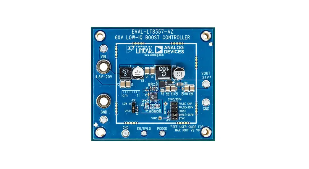
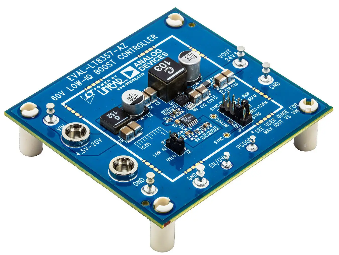
BOARD PHOTO
PERFORMANCE SUMMARY
Specifications are at TA = 25°C
| PARAMETER | CONDITIONS | MIN | TYP | MAX | UNITS |
| Input Voltage (VIN) | 24VOUT | 4.5 | 20 | V | |
| Output Voltage (VOUT) | R7 = 10MΩ, R9 = 432kΩ | 24 | V | ||
| Maximum Output Current* | 12VOUT, 4.5VIN 12VOUT, 8VIN to 20VIN | 1 2 | A A | ||
| Switching Frequency | R11 = 174kΩ, SSFM OFF R11 = 174kΩ, SSFM ON | 200 | 200 | 238 | kHz kHz |
| Input EN Voltage (Rising) | R1 = 1MΩ, R2 = 374kΩ, JP2 = UVLO | 4.5 | V | ||
| Input UVLO Voltage (Falling) | R1 = 1MΩ, R2 = 374kΩ, JP2 = UVLO | 4.3 | V | ||
| Typical Efficiency (with EMI filters) | 12VIN, 24V 2.0A Output, JP1 = BURST | 95 | % | ||
| PGOOD (Power Good) Voltage | Power Good Power NOT Good | 5.0 0 | V V | ||
| Zero Load Quiescent Current (24VOUT) JP2 = LOW IQ R7 = 10MΩ, R9 = 432kΩ | 9VIN, JP1 = PULSE SKIP 9VIN, JP1 = BURST 12VIN, JP1 = PULSE SKIP 12V,IN JP1 = BURST | 950 28 870 22 | µA µA µA µA | ||
*Please see Figure 4 and Output Voltage and Power section for more details.
QUICKSTART PROCEDURE
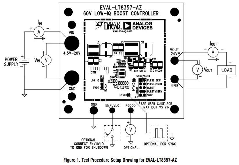
Evaluation circuit EVAL-LT8357-AZ is easy to set up to evaluate the performance of the LT8357. Refer to Figure 1 for proper measurement equipment setup and follow the procedure below:
- Connect EN/UVLO turret to GND.
- With power off, connect the input power supply to the board through VIN and GND terminals. Connect the load to the terminals VOUT and GND.
- Turn on the power at the input. Increase VIN slowly to 12V. NOTE: Make sure that the input voltage is always within specification. To operate the board with higher input/ output voltage, input and output capacitors with higher voltage ratings might be needed.
- Disconnect EN/UVLO from GND and the output turns on.
- Check for the proper output voltage. The output should be regulated at 24V and the PGOOD flag should be high (5V).
- Once the proper output voltage is established, adjust the input voltage and load current within the operating range and observe the output voltage regulation, ripple voltage, efficiency, and other parameters.
- Set JP1 and JP2 to examine the low IQ, light load operation of the LT8357. SSFM can be turned on and off with JP1 as well.
NOTE: When measuring the input or output voltage ripple, care must be taken to avoid a long ground lead on the oscilloscope probe. Measure the input or output voltage ripple by touching the probe tip directly across the input and output capacitors.
OUTPUT VOLTAGE AND POWER
The LT8357 is a low IQ boost controller. It can boost voltages up with input up to 60V and 5V gate drive MOSFETs. The 5V INTVCC provides the gate drive for the external N-channel power MOSFET. Although EVAL-LT8357-AZ is set for 24V output, the feedback resistors R7 and R9 can be easily adjusted for higher or lower output voltage. In addition to adjusting feedback resistors, the input and output capacitors should be sized appropriately. The catch diode, D1, and MOSFET, Q1, must also be able to handle the output voltage. Q1 and D1 are assembled with appropriately rated components for the 24V output application.
The peak switch’s current limit is 15A, allowing for 2A operation throughout the entire VIN range. However, the thermal limitations of some components limit full 2A DC operation below 8V. See Figure 4 to see the full DC operation maximum output current versus VIN. 2A load with transient operation down to 4.5V is allowed. The output ferrite bead limits output current to 2A maximum.
PULSE SKIP, BURST, SSFM, SYNC
The LT8357 achieves low power consumption at light loads. The different SYNC/MODE pin states can be evaluated by changing the position of jumper JP1. It is easy to change from BURST to PULSE SKIP and to explore SSFM ON, SSFM OFF, and external SYNC with this jumper.
PULSE SKIP allows low quiescent current at light load consumption without changing switching frequency until a very light load. BURST allows the lowest light load power consumption and has a unique low ripple feature on the LT8357. These two features can be explored further in the datasheet of the LT8357. For extremely light load power consumption on EVAL-LT8357-AZ, the feedback resistor R7 is set to 10MΩ, and R9 to 432kΩ resistor.
For an even lower no-load input current, the JP2 jumper should be set to LOW IQ. Then the quiescent current of the converter can drop as low as 20µA. Spread Spectrum Frequency Modulation (SSFM) can be enabled to reduce the emissions of the converter. SSFM spreads the frequency between the RT frequency and +19% higher.
If an external SYNC signal is provided, the SYNC option of JP1 can be used to synchronize with an external clock. The clock frequency should be slightly higher than the RT programmed frequency for best performance.
SPLIT GATE RESISTORS
The LT8357 features split gate drive pins. GATEP pulls the N-channel MOSFET gate high and GATEN pulls the gate low. These rates can be set separately with two different gate resistors. EVAL-LT8357-AZ features a 5.1Ω GATEP resistor R3 and a board shorted (0Ω) GATEN resistor R5. The board user can evaluate different gate speeds for a balance of emissions, efficiency, and thermal performance. If one desires to populate R5 with a resistor, the copper trace on the board must be cut.
EN/UVLO
R1 and R2 set the Undervoltage lockout falling and rising thresholds. The LT8357 data sheet gives a formula for calculating these values. EVAL-LT8357-AZ has a falling UVLO threshold of 4.3V and a rising threshold of 4.5V. This threshold can easily be adjusted by changing resistors R1 and R2 according to the datasheet equations.
PGOOD
The Power Good (PGOOD) flag indicates when the output voltage is valid on the LT8357. The PGOOD flag can be monitored with a simple multimeter at the PGOOD turret. A high signal indicates that the output voltage is within range and a low signal indicates that the output voltage is not within its valid range. See datasheet for details. The turret can be left floating when not in use.
TEST RESULTS
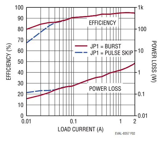
Figure 2. EVAL-LT8357-AZ Efficiency and Power Loss with VIN = 12V to VOUT = 24V. EVAL-LT8357-AZ is Assembled with EMI Filters
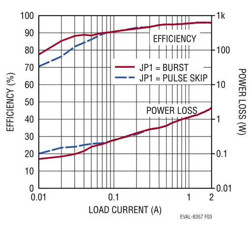
Figure 3. EVAL-LT8357-AZ Efficiency and Power Loss with VIN = 16V to VOUT = 24V. EVAL-LT8357-AZ is Assembled with EMI Filters
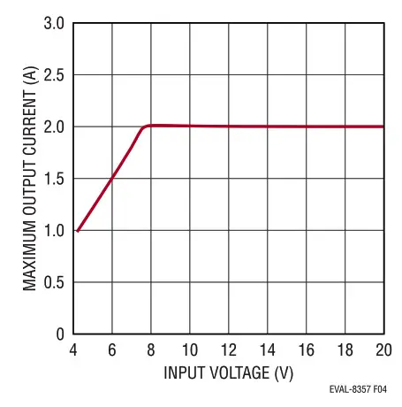
Figure 4. EVAL-LT8357-AZ Steady State Maximum Output Current vs Input Voltage
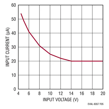
Figure 5. EVAL-LT8357-AZ No Load: Input Current vs Input Voltage with JP1 = BURST, JP2 = LOW IQ
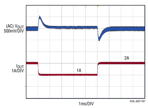
Figure 7. EVAL-LT8357-AZ VOUT Transient Response with JP1 = PULSE SKIP 12VIN 24VOUT 2A to 1A Transient
Figure 8. EVAL-LT8357-AZ CISPR25 Voltage Conducted EMI Average
Performance with 12VIN to 24VOUT at 2A, JP1 = BURST + SSFM
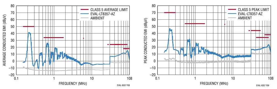
Figure 9. EVAL-LT8357-AZ CISPR25 Voltage Conducted EMI Peak Performance with 12V to 24V at 2A, JP1 = BURST + SSFM
Figure 10. EVAL-LT8357-AZ CISPR25 Radiated EMI Average Performance with 12VIN to 24VOUT at 2A, JP1 = BURST + SSFM
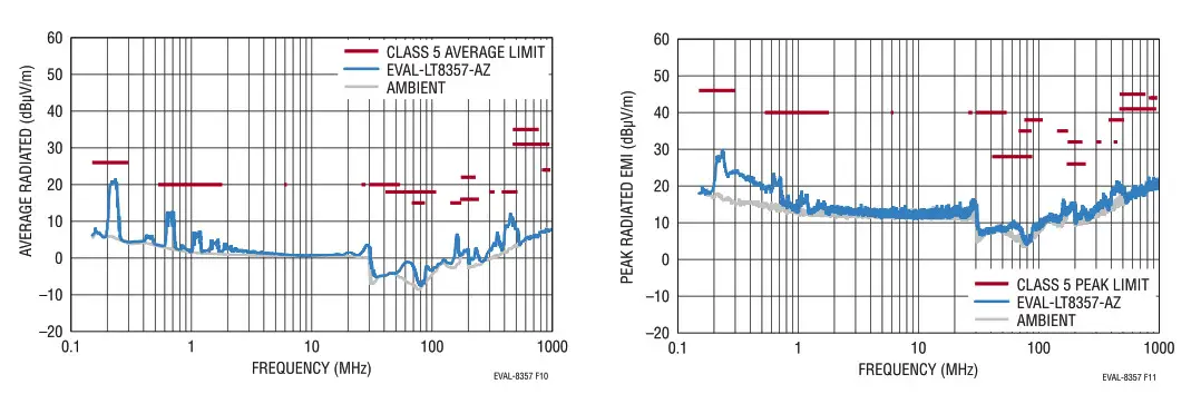
Figure 11. EVAL-LT8357-AZ CISPR25 Radiated EMI Peak Performance with 12VIN to 24VOUT at 2A, JP1 = BURST + SSFM
EMISSIONS SHIELD (OPTION)
For the ultimate lowest emissions, an EMI shield can be attached to EVAL-LT8357-AZ. The PCB was fabricated with placeholders for eight shield clips that can hold a 44mm × 44mm metal shield. Part numbers for an example shield are provided in the Parts List section under the Hardware. The top silkscreen picture (Figure 12) shows the placeholders for the eight surface mount shield clips. Then the emissions of the board can be tested with and without the removable clip shield.
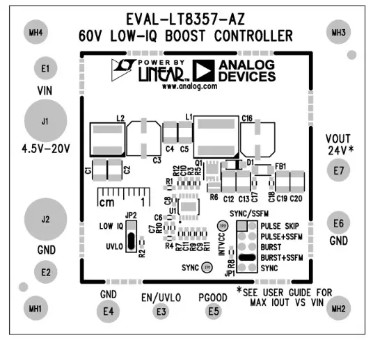
Figure 12. EMI Shield Clips Can Be Soldered to the Eight Placeholders on the PCB. A Square 44mm × 44mm Outline Shows Where the EMI Shield Fits onto the PCB
PARTS LIST
| ITEM | QTY | REFERENCE | PART DESCRIPTION | MANUFACTURER/PART NUMBER |
| Required Electrical Components | ||||
| 1 | 2 | C4, C5 | CAR, 22pF, X7R, 25V, 20%, 1210, AEC-0200 | TAIYO YUDEN, TMK325B7226MMHP |
| 2 | 1 | C7 | CAR, 0.022pF, X7R, 25V, 10%, 0603, AEC-0200 | KEMET, C0603C223K3RACAUTO |
| 3 | 1 | C8 | CAR, 1pF, X7R, 25V, 10%, 0603, AEC-0200 | MURATA, GCM188R71E105KA64D |
| 4 | 1 | C9 | CAR, 0.1pF, X7R, 50V,10%, 0603, AEC-0200 | TDK, CGA3E2X7R1H104K |
| 5 | 1 | C10 | CAR, 2.2pF, X5R, 50V,10%, 0603 | TAIYO YUDEN, UMK107BBJ225KA-T |
| 6 | 4 | C12, C13, C19, C20 | CAR, 10pF, X7S, 50V, 10%, 1210, AEC-Q200 | MURATA, GCM32EC71H106KAO3L |
| 7 | 1 | C16 | CAR, 100pF, ALUM, 35V, 20%, SMD, AEC-0200 | PANASONIC, EEHZK1V101XP |
| 8 | 1 | D1 | DIODE, SCHOTTKY, 40V, 3A, SOD-123W, AEC-13101 | NEXPERIA, PMEG4030ER |
| 9 | 1 | L1 | IND., 10pH, POWER, 20%, 8.7A, 23.1 mf2, 8.8mm x 8.3mm | COILCRAFT, XAL8080-103MEB |
| 10 | 1 | 1 | XSTR., MOSFET, N-CH, 30V, 40A, TSDSON-8 FL | INFINEON, BSZO500NSI |
| 11 | 1 | R1 | RES., 1M, 1%, 1/10W, 0603, AEC-0200 | VISHAY, CRCW06031MOOFKEA |
| 12 | 1 | R2 | RES., 374k, 1%, 1/10W, 0603, AEC-Q200 | PANASONIC, ERJ3EKF3743V |
| 13 | 1 | R6 | RES., 0.00452,1%, 1W, 0508, LONG-SIDE, AEC-Q200-SENSE | SUSUMU, KRL2012E-M-R004-F-T5 |
| 14 | 1 | R7 | RES., 10M, 1%, 1/10W, 0603, AEC-0200 | PANASONIC, ERJ3EKF1005V |
| 15 | 1 | R9 | RES., 432k, 1%, 1/10W, 0603, AEC-Q200 | NIC, NRCO6F4323TRF |
| 16 | 1 | R10 | RES., 13k, 1%, 1/10W, 0603, AEC-0200 | VISHAY, CRCW060313KOFKEA |
| 17 | 1 | R11 | RES., 174k, 1%, 1/10W, 0603, AEC-Q200 | PANASONIC, ERJ3EKF1743V |
| 18 | 1 | U1 | IC, CURRENT MODE, DC/DC CONTROLLER, WIDE INPUT RANGE, MSOP-12 | ANALOG DEVICES, LT8357JMSE#PBF |
| Optional Low EMI Components | ||||
| 1 | 2 | C1, C2 | CAP, 22pF, X7R, 25V, 20%, 1210, AEC-Q200 | TAIYO YUDEN, TMK325B7226MMHP |
| 2 | 1 | C3 | CAP, 68pF, ALUM ELECT 25V, 20%, 6.3mm x 5.8mm, RADIAL, SMD, AEC-0200 | PANASONIC, EEEFN1E680P |
| 3 | 2 | C17, C18 | CAP, 1pF, X5R, 50V, 10%, 0603, AEC-0200 | TAIYO YUDEN, UMK107ABJ105KAHT |
| 4 | 1 | FB1 | IND., 60052 AT 100MHz, FERRITE BEAD, 25%, 2A, 100mQ, 1206 | WURTH, 74279218 |
| 5 | 1 | L2 | IND., 1.5pH, SHIELDED PWR, 20%, 10.3A, 6.2mQ, 6.71mm x 6.51 mm, AEC-Q200 | COILCRAFT, XGL6030-152MEB |
| 6 | 1 | R3 | RES., 5.152, 1%, 1/10W, 0603, AEC-Q200 | VISHAY, CRCW06035R1OFKEA |
| 7 | 0 | R5 | RES., OPTION, 0603 | |
| Optional Electrical Components | ||||
| 1 | 0 | C6, C11 | CAP, OPTION, 0603 | |
| 2 | 0 | R4 | RES., OPTION, 0603 | |
| 3 | 2 | R8, R12 | RES., 100k, 1%, 1/10W, 0603, AEC-0200 | VISHAY, CRCW0603100KFKEA |
| ITEM | I QTY | I REFERENCE | I PART DESCRIPTION | MANUFACTURER/PART NUMBER | ||||
| Hardware: For Evaluation Circuit Only | ||||||||
| 1 | 5 | E1, E2, E4, E6, E7 | TEST POINT TURRET 0.094″ MTG. HOLE, PCB 0.062″ THK | MILL-MAX, 2501-2-00-80-00-00-07-0 | ||||
| 2 | 2 | E3, E5 | TEST POINT TURRET 0.064″ MTG. HOLE, PCB 0.062″ THK | MILL-MAX, 2308-2-00-80-00-00-07-0 | ||||
| 3 | 2 | J1, J2 | CONN., BANANA JACK, FEMALE, THT, NON INSULATED, SWAGE, 0.218″ | KEYSTONE, 575-4 | ||||
| 4 | 1 | JP1 | CONN., HDR, MALE, 2×5, 2mm, VERT, ST THT | WURTH ELEKTRONIK, 62001021121 | ||||
| 5 | 1 | JP2 | CONN., HDR., MALE, 1×3, 2mm, VERT, ST THT | SULLINS CONNECTOR SOLUTIONS, NRPNO31PAEN-RC | ||||
| 6 | 4 | MP1, MP2, MP3, MP4 | STANDOFF NYLON, SNAP-ON, 0.50″ | KEYSTONE, 8833 | ||||
| 7 | 2 | XJP1, XJP2 | CONN., SHUNT FEMALE, 2-POS, 2mm | WURTH ELEKTRONIK, 60800213421 | ||||
| 8 | 0 | CL1-CL8 | EIGHT EMI SHIELD CLIPS | WURTH ELEKTRONIK, 36900000 | ||||
| 9 | 0 | SH1 | EMI SHIELD 44mm x 44mm | WURTH ELEKTRONIK, 36907406S | ||||
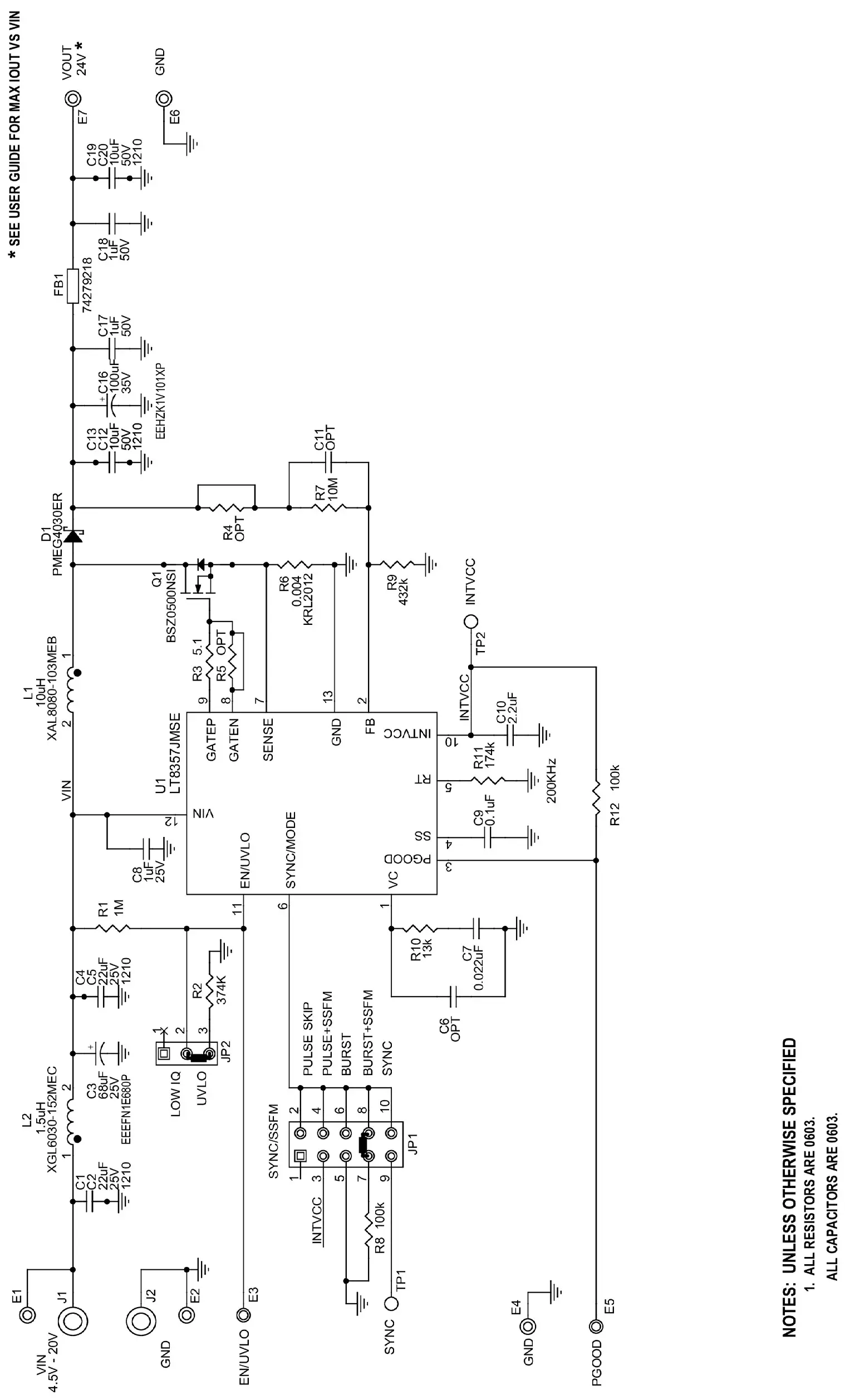
SCHEMATIC DIAGRAM
Information furnished by Analog Devices is believed to be accurate and reliable. However, no responsibility is assumed by Analog Devices for its use, nor for any infringements of patents or other rights of third parties that may result from its use. Specifications are subject to change without notice. No license is granted by implication or otherwise under any patent or patent rights of Analog Devices.
 ESD Caution
ESD (electrostatic discharge) sensitive device. Charged devices and circuit boards can discharge without detection. Although this product features patented or proprietary protection circuitry, damage may occur on devices subjected to high-energy ESD. Therefore, proper ESD precautions should be taken to avoid performance degradation or loss of functionality.
Legal Terms and Conditions
By using the evaluation board discussed herein (together with any tools, components documentation, or support materials, the “Evaluation Board”), you are agreeing to be bound by the terms and conditions set forth below (“Agreement”) unless you have purchased the Evaluation Board, in which case the Analog Devices Standard Terms and Conditions of Sale shall govern. Do not use the Evaluation Board until you have read and agreed to the Agreement. Your use of the Evaluation Board shall signify your acceptance of the Agreement. This Agreement is made by and between you (“Customer”) and Analog Devices, Inc. (“ADI”), with its principal place of business at One Technology Way, Norwood, MA 02062, USA. Subject to the terms and conditions of the Agreement, ADI hereby grants to Customer a free, limited, personal, temporary, non-exclusive, non-sublicensable, non-transferable license to use the Evaluation Board FOR EVALUATION PURPOSES ONLY. The customer understands and agrees that the Evaluation Board is provided for the sole and exclusive purpose referenced above, and agrees not to use the Evaluation Board for any other purpose. Furthermore, the license granted is expressly made subject to the following additional limitations: Customer shall not (i) rent, lease, display, sell, transfer, assign, sublicense, or distribute the Evaluation Board; and (ii) permit any Third Party to access the Evaluation Board. As used herein, the term “Third Party” includes any entity other than ADI, Customer, their employees, affiliates, and in-house consultants. The Evaluation Board is NOT sold to Customer; all rights not expressly granted herein, including ownership of the Evaluation Board, are reserved by ADI. CONFIDENTIALITY. This Agreement and the Evaluation Board shall all be considered the confidential and proprietary information of ADI. The customer may not disclose or transfer any portion of the Evaluation Board to any other party for any reason. Upon discontinuation of use of the Evaluation Board or termination of this Agreement, Customer agrees to promptly return the Evaluation Board to ADI. ADDITIONAL RESTRICTIONS. The customer may not disassemble, decompile or reverse engineer chips on the Evaluation Board. The customer shall inform ADI of any occurred damages or any modifications or alterations it makes to the Evaluation Board, including but not limited to soldering or any other activity that affects the material content of the Evaluation Board. Modifications to the Evaluation Board must comply with applicable law, including but not limited to the RoHS Directive. TERMINATION. ADI may terminate this Agreement at any time upon giving written notice to the Customer. The customer agrees to return to ADI the Evaluation Board at that time. LIMITATION OF LIABILITY. THE EVALUATION BOARD PROVIDED HEREUNDER IS PROVIDED “AS IS” AND ADI MAKES NO WARRANTIES OR REPRESENTATIONS OF ANY KIND WITH RESPECT TO IT. ADI SPECIFICALLY DISCLAIMS ANY REPRESENTATIONS, ENDORSEMENTS, GUARANTEES, OR WARRANTIES, EXPRESS OR IMPLIED, RELATED TO THE EVALUATION BOARD INCLUDING, BUT NOT LIMITED TO, THE IMPLIED WARRANTY OF MERCHANTABILITY, TITLE, FITNESS FOR A PARTICULAR PURPOSE, OR NON-INFRINGEMENT OF INTELLECTUAL PROPERTY RIGHTS. IN NO EVENT WILL ADI AND ITS LICENSORS BE LIABLE FOR ANY INCIDENTAL, SPECIAL, INDIRECT, OR CONSEQUENTIAL DAMAGES RESULTING FROM CUSTOMER’S POSSESSION OR USE OF THE EVALUATION BOARD, INCLUDING BUT NOT LIMITED TO LOST PROFITS, DELAY COSTS, LABOR COSTS OR LOSS OF GOODWILL. ADI’S TOTAL LIABILITY FROM ANY AND ALL CAUSES SHALL BE LIMITED TO THE AMOUNT OF ONE HUNDRED US DOLLARS ($100.00). EXPORT. The customer agrees that it will not directly or indirectly export the Evaluation Board to another country and that it will comply with all applicable United States federal laws and regulations relating to exports. GOVERNING LAW. This Agreement shall be governed by and construed in accordance with the substantive laws of the Commonwealth of Massachusetts (excluding conflict of law rules). Any legal action regarding this Agreement will be heard in the state or federal courts having jurisdiction in Suffolk County, Massachusetts, and Customer hereby submits to the personal jurisdiction and venue of such courts. The United Nations Convention on Contracts for the International Sale of Goods shall not apply to this Agreement and is expressly disclaimed.
![]()
Rev. 0
08/21
www.analog.com
©ANALOG DEVICES, INC. 2021


