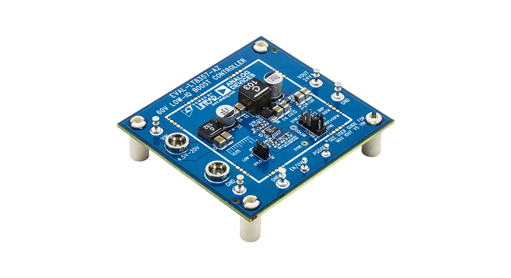
![]() EVAL-LT8391D-AZ Evaluation Board
EVAL-LT8391D-AZ Evaluation Board
User Manual
LT8391D
Synchronous 4-Switch Buck-Boost LED
Driver 6V to 45V Input, Up to 50V LED
DESCRIPTION
Evaluation circuit EVAL-LT8391D-AZ is a 4-switch synchronous buck-boost LED driver featuring the LT® 8391D.
It drives a single string of LEDs at up to 1.5A and up to 50V when VIN is between 6V and 45V. EVAL-LT8391D-AZ runs at 400kHz switching frequency and efficiency can exceed 97%. It comes with low EMI features including optimized layout, spread spectrum frequency modulation (SSFM), and input EMI filter. SSFM can be turned on or off
with a simple jumper.
The LT8391D 4-switch buck-boost controller is the new member of the LT8391 family (see Table 1). It has an input voltage range of 4V to 60V and an output voltage range of 0V to 60V. It has input under voltage lockout (UVLO) which can also be used to enable or disable the controller. On the output side, it is protected against both open and short LED conditions.
The LT8391D allows adjustable switching frequencies between 150kHz and 650kHz. It can be PWM dimmed with an external PWM signal. When run with PWM dimming and either fixed switching frequency or SSFM, the internal oscillator aligns itself with the PWM signal for flicker-free operation. On EVAL-LT8391D-AZ, the PWM pin is pulled up to INTVCC through a 100k resistor. Therefore, the LED string is 100% ON when there is no external PWM signal.
It can also be analog dimmed with a control voltage on its control pin (CTRL).
EVAL-LT8391D-AZ features MOSFETs that complement the 5V gate drive of the LT8391D to achieve high efficiency. All MOSFETs used on the 4-switch topology are rated at 60V and AEC-Q101 qualified. Ceramic capacitors are used at both the input and output sides due to their small size and high ripple current capability. In addition to ceramic capacitors, there is one aluminum electrolytic capacitor at the input side to mitigate the effects of the input and output transients.
Sense resistor for LED current can be placed either on the high side (LED+) or the low side (GND). With a high-side sense resistor, LED– is directly connected to GND. This gives the option to run only one wire (LED+) to LED string and use chassis ground as a return path in automotive or similar applications. LT8391D guarantees ±4% current regulation accuracy with a high-side sense resistor. Low-side sense resistor gives the most accurate LED current regulation.
EVAL-LT8391D-AZ implemented both high-side and low-side sense resistors, with the high-side sense resistor as default and the low-side sense resistor as optional.
The LT8391D data sheet gives a complete description of the part, operation, and application information. The data sheet must be read in conjunction with this user guide for evaluation circuit EVAL-LT8391D-AZ. The LT8391DJUFDM is assembled in a 28-lead plastic 4mm × 5mm QFN package with a thermally enhanced GND pad.
The proper board layout is essential for maximum thermal performance and EMI performance. Please see the evaluation kit design files for details, including top layer layout, inner traces, and grounding.
Refer to the Emission Results section for the excellent EMI performance of this evaluation board.
Table 1. Comparison of LT839X Family
| LT8391 | LT8391A | LT8391D | LT8393 | |
| VIN Range | 4V – 60V | 4V – 60V | 4V – 60V | 4V – 60V |
| VOuT Range | OV – 60V | OV – 60V | OV – 60V | OV – 100V |
| fsw | 150kHz – 650kHz | 600kHz – 2MHz | 150kHz – 650kHz | 350kHz – 2MHz |
| Clock Sync | Yes | Yes | No | Yes |
| SSFM | Yes | Yes | Yes | Yes |
| PWM Dimming | External and 128:1 Internal | External and 128:1 Internal | External | External and 128:1 Internal |
| PWM Driver | 5V High Side | 5V High Side | N/A | 10V High Side |
| FB Short LED Threshold | 0.25V Falling | 0.25V Falling | 0.05V Falling | 0.25V Falling |
| Package | FE28 and UFD28 | FE28 and UFD28 | UFDM28 | FE28 and UFDM28 |
| Temperature Range | -40°C to 150°C | -40°C to 150°C | -40°C to 150°C | -40°C to 150°C |
| Price | Normal | Low | Lowest | Normal |
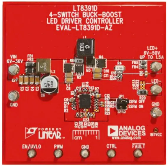
BOARD PHOTO
PERFORMANCE SUMMARY
Specifications are at TA = 25°C
| PARAMETER | CONDITION | MIN | TYP | MAX | UNIT |
| Input Voltage VIN Range (Output 22.5W) | Operating. 6V VLED 50V, ILED 1.5A | 6 | 45 | V | |
| Input Voltage VIN Range (Output 45W) | Operating, 6V VLED 36V. LED 1.5A | 9 | 45 | V | |
| Safe Input Voltage VIN Range | 0 | 50 | V | ||
| VIN Undervoltage Lockout (UVLO) Falling | Operating, VLED = 30V, ILED = 1.5A | 4.2 | V | ||
| VIN Enable Turn-On (EN) Rising | 5.0 | V | |||
| Switching Frequency (FSW) | R17 =100k. SSFM = OFF R17 = 100k. SSFM = ON | 400 340 to 460 | kHz kHz | ||
| LED Current ILED | R4 = 0.0685. 9V < VIN < 45V. 6V VLED 30V, VCTRL = 2V | 1.47 | A | ||
| LED Voltage VLED Range | R15 = 1M. R16 = 17.4k | 6 | 50 | V | |
| Open LED Voltage V0UT | R15 = 1M. R16 = 17.4k | 55.5 | V | ||
| Efficiency (100% PWM DC) | VIN = 12.0V, VLED = 30V, ILED = 1.5A, SSFM = ON or OFF. EMI Filters Included | 94 | % |
QUICK START PROCEDURE
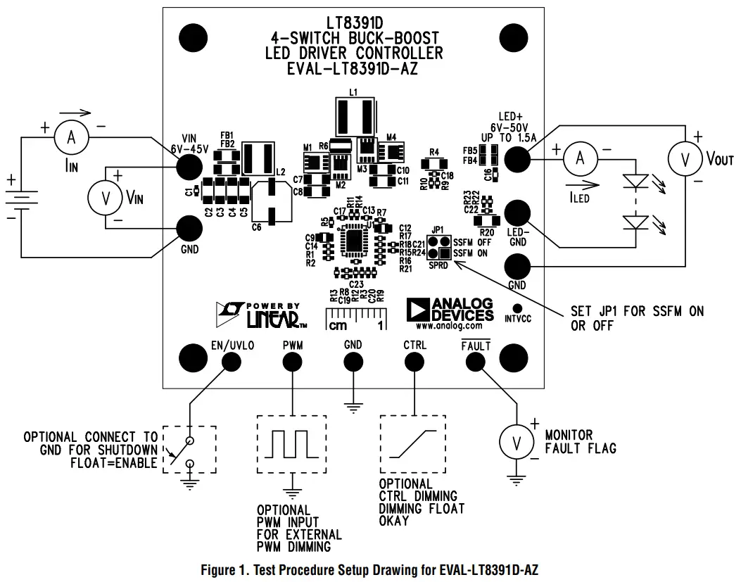
The EVAL-LT8391D-AZ is easy to set up to evaluate the performance of the LT8391D. Refer to Figure 1 for proper measurement equipment setup and follow the procedure below.
NOTE: Make sure that the voltage applied to VIN does not exceed 50V.
- With power off, connect a string of LEDs that runs with a forward voltage less than or equal to 50V at 1.5A to the LED+ and LED– terminals.
- Connect the EN/UVLO terminal to GND.
- To enable spread spectrum frequency modulation, set JP1 to “SSFM ON”. Setting JP1 to “SSFM OFF” turns off SSFM.
- With power off, connect the input power supply to the VIN and GND terminals.
- Turn the input power supply on and make sure the voltage is between 6V and 45V for proper operation.
- Release the EN/UVLO-to-GND connection.
- Observe the LED string running at the programmed LED current.
- To change the brightness with analog dimming, simply attach a voltage source to the CTRL terminal and set the voltage between 0V and 1.35V. See the datasheet for details.
- To change brightness with external PWM dimming, attach a 0V to 3V rectangular waveform with varying duty cycles to the PWM terminal.
Optimize Efficiency
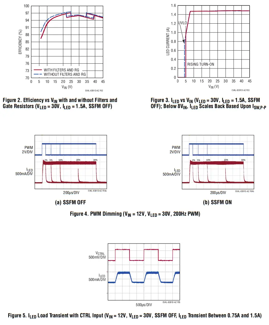
If the EMI performance is less of a priority than efficiency and thermal performance, the EMI filters and gate resistors for MOSFETs can be removed (short the ferrite beads and inductor in EMI filters and short all gate resistors).
The components for EMI filters are listed separately in the parts list. The gate resistors are R5, R7, R11, and R14.
Figure 2 gives the efficiency curves with and without EMI filters and gate resistors.
High Side and Low Side Sense Resistors
EVAL-LT8391D-AZ implemented both high-side and low-side LED current sense resistors to facilitate different application requirements. With a high-side sense resistor, LED– is directly connected to GND. This gives the option to run only one wire (LED+) to LED string and use chassis ground as a return path in automotive or similar applications.
If this feature is not necessary, the sense resistor can be placed on the low side to get the most accurate current regulation. By default, EVAL-LT8391D-AZ is assembled with a high-side sense resistor. To switch to low side sense resistor, please follow these steps:
- Remove R9, R10, and short R4.
- Populate R22 and R23 with 0Ω resistors.
- Populate C22 with a 2.2μF/6.3V capacitor (same part number as C18).
- Cut the trace that shorts R20 and populate R20 with 0.068Ω resistor (same part number as R4).
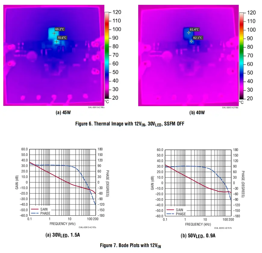
TEST RESULTS
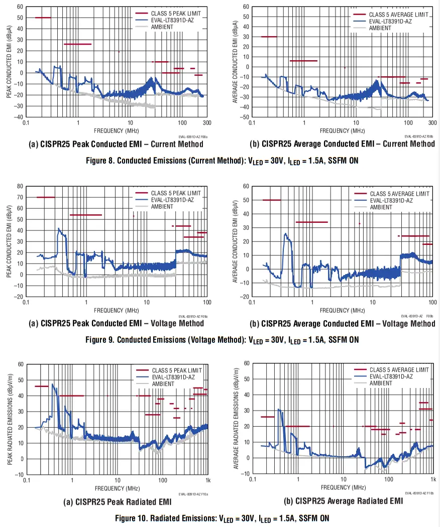
EMISSION RESULTS
PARTS LIST
| ITEM | QTY | REFERENCE | PART DESCRIPTION | MANUFACTURER/PART NUMBER |
| Required Electrical Components | ||||
| 1 | 2 | C7, C8 | CAP., 10p F, X5R, 50V,10%, 1206, AEC-0200 | MURATA, GRT31CR61H106KEO1L |
| 2 | 1 | C9 | CAP., 1 p F, X7R, 50V,10%, 0805, AEC-0200 | MURATA, GCM21BR71H105KAO3L |
| 3 | 2 | C10, C11 | CAP., 4.7pF, X7S, 100V, 20%, 1 206 | MURATA, GRM31CC72A475ME11L |
| 4 | 1 | C12 | CAP., 1p F, X7S, 100V, 10%, 0805, AEC-0200 | MURATA, GCM21BC72A105KE36L |
| 5 | 3 | C13, C17, C20 | CAP, 0.1pF, X7R, 16V, 10%, 0402, AEC-0200 | MURATA, GCM1 55R71C104KA55D |
| 6 | 1 | C14 | CAP., 4.7pF, X5R, 6.3V, 20%, 0402, AEC-0200 | TAIYO YUDEN, JMK1 05BBJ475MVHF |
| 7 | 1 | C18 | CAP., 2.2pF, X5R, 6.3V, 20%, 0402, AEC-0200 | TAIYO YUDEN, JMK1 05BJ225MVHF |
| 8 | 1 | C19 | CAP, 0.47p F, X7R, 6.3V, 10%, 0402, AEC-0200 | TAIYO YUDEN, JMK1 05B7474KVHF |
| 9 | 1 | C21 | CAP, 6800pF, X7R, 50V, 10%, 0402, AEC-0200 | MURATA, GCM1 55R71H682KA55D |
| 10 | 1 | Ll | IND., 10pH, SHIELDED PWR, 20%, 7A, 29.82mQ, 6.56mm x 6.36mm, AEC-0200 | COILCRAFT, XAL6060-1 03MEB |
| 11 | 4 | M1-M4 | XSTR., MOSFET, N-CH, 60V, 38A, LFPAK33, AEC-0101 | NEXPERIA, BUK9M19-60EX |
| 12 | 1 | R1 | RES., 3 83k, 1%, 1/1 6W, 0402, AEC-0200 | VISHAY, CRCW04023 83KFKED |
| 13 | 1 | R2 | RES., 1 65k, 1%, 1/16W, 0402, AEC-0200 | VISHAY, CRCW04021 65KFKED |
| 14 | 2 | R3, R17 | RES., 1 00k, 1%, 1/1 6W, 0402, AEC-0200 | VISHAY, CRCW04021 LOOKED |
| 15 | 1 | R4 | RES., 0.068Q, 1%, 3/4W, 1206, SHORT SIDE TERM, AEC-0200 | SUSUMU, KRL163 2E-M-R06 8-F-T5 |
| 16 | 4 | R5, R7, R11, R14 | RES., 252, 1%, 1/16W, 0402, AEC-0200 | VISHAY, CRCW04022ROOFKED |
| 17 | 1 | R6 | RES., 0.00752, 1%, 1.5W, 1206, LONG SIDE TERM, METAL SENSE, AEC-0200 | SUSUMU, KRL321 6E-M-R007-F-T1 |
| 18 | 2 | R8, R13 | RES., 1 00k, 5%, 1/16W, 0402, AEC-0200 | VISHAY, CRCW04021 OOKJNED |
| 19 | 2 | R9, R10 | RES., 052,1/10W, 0402, AEC-Q200 | PANASONIC, ERJ2GEOROOX |
| 20 | 1 | R15 | RES., 1M, 1%, 1/16W, 0402, AEC-0200 | VISHAY, CRCW04021 MOOFKED |
| 21 | 1 | R16 | RES., 1 7.4k, 1%, 1/16W, 0402, AEC-0200 | VISHAY, CRCW04021 7K4FKED |
| 22 | 1 | R18 | RES., 2.2k, 1%, 1/10W, 0402, AEC-0200 | PANASONIC, ERJ2RKF2201X |
| 23 | 1 | R20 | RES., 00, 1/4W, 1 206, AEC-0200 | VISHAY, CRCW1 2060 000Z0EA |
| 24 | 1 | U1 | IC, 4-SWITCH BUCK-BOOST CTRLR, QFN-28, WETTABLE | ANALOG DEVICES, LT8391DJUFDM#WPBF |
| Optional EMI Filter Components | ||||
| 25 | 1 | C1 | CAP, 0.1pF, X7R, 50V,10%, 0402, AEC-0200 | MURATA, GCM1 55R71H104KEO2D |
| 26 | 4 | C2-05 | CAP, 10pF, X5R, 50V, 10%, 1 206, AEC-0200 | MURATA, GRT31CR61H106KEO1L |
| 27 | 1 | C6 | CAP, 47p F, ALUM ELECT, 50V, 20%, 6.3mm x 5.8mm SMD, RADIAL, AEC-0200 | PANASONIC, EEEFT1 H470AP |
| 29 | 1 | C16 | CAP, 0.1pF, X7R, 100V, 10%, 0805, AEC-0200 | MURATA, GCM21BR72A104KA37L |
| 30 | 2 | FB1, FB2 | IND., 47052 AT 100MHz, FERRITE BEAD, 25%, 4A, 20m12, 120 6, AEC-0200 | MURATA, BLM31KN4 71SZ1L |
| 31 | 2 | FB4, FB5 | IND., 1k AT 100MHz, FERRITE BEAD, 25%, 1.5A, 150mQ, 0805, AEC-0200 | TDK, MPZ2012S1 02ATD25 |
| 32 | 1 | L2 | IND., 3.3pH, SHIELDED, 20%, 10.6A, 14.6mQ, 5.48mm x 5.28mm, AEC-0200 | COILCRAFT, XEL5050-332MEB |
| Additional Electrical Components | ||||
| 33 | 2 | C22, C23 | CAP, OPTION, 0402 | |
| 34 | 6 | R12, R19, R21-R24 | RES., OPTION, 04 02 | |
| Hardware: Fo Demo Board Only | ||||
| 35 | 5 | El, E2, E7, E9, El 0 | TEST POINT, TURRET, 0.094′ MTG. HOLE, PCB 0.062′ THK | MILL-MAX 2501-2-00-80-00-00-07-0 |
| 36 | 5 | E3-E6, E8 | TEST POINT, TURRET, 0.064′ MTG. HOLE, PCB 0.062′ THK | MILL-MAX 2308-2-00-80-00-W-07-0 |
| 37 | 1 | JP1 | CONN., HDR, MALE, 2×2, 2mm, VERT, STR, THT | WURTH ELEKTRONIK, 62000421121 |
| 38 | 1 | XJP1 | CONN., SHUNT, FEMALE, 2 POS, 2mm | WURTH ELEKTRONIK, 60800213421 |
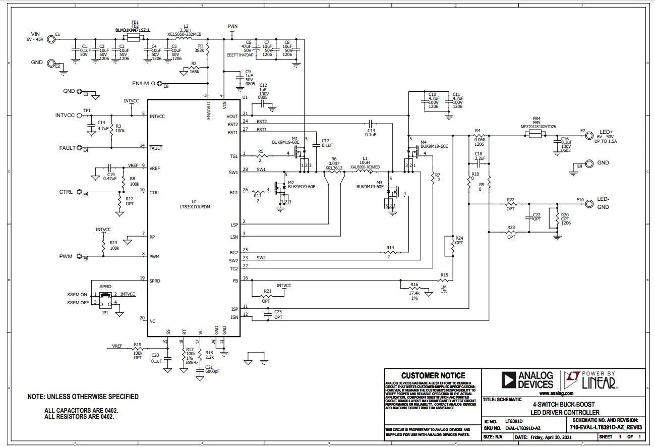
SCHEMATIC DIAGRAM
Information furnished by Analog Devices is believed to be accurate and reliable. However, no responsibility is assumed by Analog
Devices for its use, nor for any infringements of patents or other rights of third parties that may result from its use. Specifications are subject to change without notice. No license is granted by implication or otherwise under any patent or patent rights of Analog Devices.
![]() ESD Caution
ESD Caution
ESD (electrostatic discharge) sensitive device. Charged devices and circuit boards can discharge without detection. Although this product features patented or proprietary protection circuitry, damage may occur on devices subjected to high-energy ESD. Therefore, proper ESD precautions should be taken to avoid performance degradation or loss of functionality.
Legal Terms and Conditions
By using the evaluation board discussed herein (together with any tools, components documentation, or support materials, the “Evaluation Board”), you are agreeing to be bound by the terms and conditions set forth below (“Agreement”) unless you have purchased the Evaluation Board, in which case the Analog Devices Standard Terms and conditions of Sale shall govern. Do not use the Evaluation Board until you have read and agreed to the Agreement. Your use of the Evaluation Board shall signify your acceptance of the Agreement. This Agreement is made by and between you (“Customer”) and Analog Devices, Inc. (“ADI”), with its principal place of business at One Technology Way, Norwood, MA 02062, USA. Subject to the terms and conditions of the Agreement, ADI hereby grants to Customer a free, limited, personal, temporary, non-exclusive, non-sublicensable, non-transferable license to use the Evaluation Board FOR EVALUATION PURPOSES ONLY. The customer understands and agrees that the Evaluation Board is provided for the sole and exclusive purpose referenced above, and agrees not to use the Evaluation Board for any other purpose. Furthermore, the license granted is expressly made subject to the following additional limitations: Customer shall not (i) rent, lease, display, sell, transfer, assign, sublicense, or distribute the Evaluation board; and (ii) permit any Third Party to access the Evaluation Board. As used herein, the term “Third Party” includes any entity other than ADI, Customers, their employees, affiliates, and in-house consultants. The Evaluation Board is NOT sold to Customer; all rights not expressly granted herein, including ownership of the Evaluation Board, are reserved by ADI. CONFIDENTIALITY. This Agreement and the Evaluation Board shall all be considered the confidential and proprietary information of ADI. The customer may not disclose or transfer any portion of the Evaluation Board to any other party for any reason. Upon discontinuation of use of the Evaluation Board or termination of this Agreement, Customer agrees to promptly return the Evaluation Board to ADI. ADDITIONAL RESTRICTIONS. Customers may not disassemble, decompile or reverse engineer chips on the Evaluation Board. Customer shall inform ADI of any occurred damages or any modifications or alterations it makes to the Evaluation Board, including but not limited to soldering or any other activity that affects the material content of the Evaluation Board. Modifications to the Evaluation Board must comply with applicable law, including but not limited to the RoHS Directive. TERMINATION. ADI may terminate this Agreement at any time upon giving written notice to Customer. The customer agrees to return to ADI the Evaluation Board at that time. LIMITATION OF LIABILITY. THE EVALUATION BOARD PROVIDED HEREUNDER IS PROVIDED “AS IS” AND ADI MAKES NO WARRANTIES OR REPRESENTATIONS OF ANY KIND WITH RESPECT TO IT. ADI SPECIFICALLY DISCLAIMS ANY REPRESENTATIONS, ENDORSEMENTS, GUARANTEES, OR WARRANTIES, EXPRESS OR IMPLIED, RELATED TO THE EVALUATION BOARD INCLUDING, BUT NOT LIMITED TO, THE IMPLIED WARRANTY OF MERCHANTABILITY, TITLE, FITNESS FOR A PARTICULAR PURPOSE, OR NON-INFRINGEMENT OF INTELLECTUAL PROPERTY RIGHTS. IN NO EVENT WILL ADI AND ITS LICENSORS BE LIABLE FOR ANY INCIDENTAL, SPECIAL, INDIRECT, OR CONSEQUENTIAL DAMAGES RESULTING FROM THE CUSTOMER’S POSSESSION OR USE OF THE EVALUATION BOARD, INCLUDING BUT NOT LIMITED TO LOST PROFITS, DELAY COSTS, LABOR COSTS, OR LOSS OF GOODWILL. ADI’S TOTAL LIABILITY FROM ANY AND ALL CAUSES SHALL BE LIMITED TO THE AMOUNT OF ONE HUNDRED US DOLLARS ($100.00). EXPORT. The customer agrees that it will not directly or indirectly export the Evaluation Board to another country and that it will comply with all applicable United States federal laws and regulations relating to exports. GOVERNING LAW. This Agreement shall be governed by and construed in accordance with the substantive laws of the Commonwealth of Massachusetts (excluding conflict of law rules). Any legal action regarding this Agreement will be heard in the state or federal courts having jurisdiction in Suffolk County, Massachusetts, and Customer hereby submits to the personal jurisdiction and venue of such courts. The United Nations Convention on Contracts for the International Sale of Goods shall not apply to this Agreement and is expressly disclaimed.


