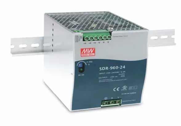
Mean Well SDR-960-48 Industrial DIN rail power supply
Features
- AC input 180-264VAC only
- 130% peak load capability
- 110mm slim design
- Built-in active PFC function compliance to BS EN/EN61000-3-2
- High efficiency 94% and low power dissipation
- Protections: Short circuit/ Overload /Over voltage/Over temperature
- Cooling by free air convection
- Built-in constant current limiting circuit
- Can be installed on DIN rail TS-35/7.5 or 15
- UL508(industrial control equipment)approved
- BS EN/EN61000-6-2(BS EN/EN50082-2) industrial immunity level
- Current sharing up to 3840VW(3+1)
- Built-in DC OK relay contact
- 100% full load burn-in test
- 3 years warranty
GTIN CODE
MW Search: htps://www.meanwell.com/serviceGIN.aspx
SPECIFICATION
| MODEL | SDR-960-24 | SDR-960-48 | |
|
OUTPUT | DC VOLTAGE | 24V | 48V |
| RATED CURRENT | 40A | 20A | |
| CURRENT RANGE | 0 ~ 40A | 0 ~ 20A | |
| RATED POWER | 960W | 960W | |
| PEAK CURRENT | 52A | 26A | |
| PEAK POWER Note.6 | 1248W (3sec.) | ||
| RIPPLE & NOISE (max.) Note.2 | 180mVp-p | 250mVp-p | |
| VOLTAGE ADJ. RANGE | 24 ~ 28V | 48 ~ 55V | |
| VOLTAGE TOLERANCE Note.3 | ±1.0% | ±1.0% | |
| LINE REGULATION | ±0.5% | ±0.5% | |
| LOAD REGULATION | ±1.0% | ±1.0% | |
| SETUP, RISE TIME | 1000ms, 100ms/230VAC at full load | ||
| HOLD UP TIME (Typ.) | 14ms / 230VAC at full load | ||
|
INPUT | VOLTAGE RANGE Note.7 | 180 ~ 264VAC 254 ~ 370VDC | |
| FREQUENCY RANGE | 47 ~ 63Hz | ||
| POWER FACTOR (Typ.) | PF≧0.95/230VAC at full load | ||
| EFFICIENCY (Typ.) | 94% | 94% | |
| AC CURRENT (Typ.) | 6A/230VAC | ||
| INRUSH CURRENT (Typ.) | COLD START 50A / 230VAC | ||
| LEAKAGE CURRENT | <3.5mA / 240VAC | ||
|
PROTECTION | OVERLOAD | Normally works within 105 ~ 130% rated output power for more than 3 seconds and then shut down o/p voltage with auto-recovery after 30 seconds if the peak load condition is removed | |
| Constant current limiting within 130 ~ 150% rated output power for more than 3 seconds and then shut down o/p voltage, re-power on to recover | |||
| OVER VOLTAGE | 29 ~ 33V | 56 ~ 65V | |
| Protection type : Shut down o/p voltage, with auto-recovery or re-power on to recover | |||
| OVER TEMPERATURE | Shut down o/p voltage, recovers automatically after temperature goes down | ||
| FUNCTION | DC OK REALY CONTACT RATINGS (max.) | 60Vdc/0.3A, 30Vdc/1A, 30Vac/0.5A resistive load | |
| CURRENT SHARING | Please refer to function manual | ||
|
ENVIRONMENT | WORKING TEMP. Note.5 | -30 ~ +70℃ (Refer to “Derating Curve”) | |
| WORKING HUMIDITY | 20 ~ 95% RH non-condensing | ||
| STORAGE TEMP., HUMIDITY | -40 ~ +85℃, 10 ~ 95% RH non-condensing | ||
| TEMP. COEFFICIENT | ±0.03%/℃ (0 ~ 50℃) | ||
| VIBRATION | Component:10 ~ 500Hz, 2G 10min./1cycle, 60min. each along X, Y, Z axes; Mounting: Compliance to IEC60068-2-6 | ||
| SAFETY & EMC (Note 4) | SAFETY STANDARDS | UL508, TUV BS EN/EN62368-1, BSMI CNS14336-1, AS/NZS62368.1, EAC TP TC 004 approved ; (meet BS EN/EN60204-1) | |
| WITHSTAND VOLTAGE | I/P-O/P:3KVAC I/P-FG:2KVAC O/P-FG:0.5KVAC O/P-DC OK:0.5KVAC | ||
| ISOLATION RESISTANCE | I/P-O/P, I/P-FG, O/P-FG:>100M Ohms / 500VDC / 25℃/ 70% RH | ||
| EMC EMISSION Note.8 | Compliance to BS EN/EN55032 (CISPR32), BS EN/EN61204-3 Conduction class B, Radiation class A, BS EN/EN61000-3-2,-3, EAC TP TC 020, BSMI CNS13438 | ||
| EMC IMMUNITY | Compliance to BS EN/EN61000-4-2,3,4,5,6,8,11, BS EN/EN55024, BS EN/EN61000-6-2 (BS EN/EN50082-2), BS EN/EN61204-3, heavy industry level, EAC TP TC 020 | ||
| OTHERS | MTBF | 660.2K hrs min. Telcordia SR-332 (Bellcore) ; 70.7K hrs min. MIL-HDBK-217F (25℃) | |
| DIMENSION | 110*125.2*150mm (W*H*D) | ||
| PACKING | 2.47Kg ; 6pcs/15.8Kg/1.55CUFT | ||
| NOTE | 1. All parameters NOT specially mentioned are measured at 230VAC input, rated load and 25C of ambient temperature. 2. Ripple & noise are measured at 20MHz of bandwidth by using a 12″ twisted pair-ire terminated with a 0.1uf & 47uf parallel capacitor. 3. Tolerance: includes set up tolerance, line regulation and load regulation. 4. The power supply is considered a component which will be installed into a final equipment. The final equipment must be re-confirmed that it still meets EMC directives. 5. Installation clearances: 40mm on top, 20mm on the bottom, 5mm on the left and right side are recommended when loaded permanently with full power. In case the adjacent device is a heat source, 15mm clearance is recommended. 5. 3 seconds peak power max. and the average output power should not exceed the rate power. 7. Derating may be needed under low input voltage. Please check the derating curve for more details. 3. Consult MEAN WELL for deployment of Radiation class B. 9. The ambient temperature derating of 3.5C/1000m with fanless models and of 5 C/1000m with fan models for operating altitude higher than 2000m(6500ft). XProduct Liability Disclaimer : For detailed information, please refer to https://www.meanwell.com/serviceDisclaimer.aspx | ||
Mechanical Specification
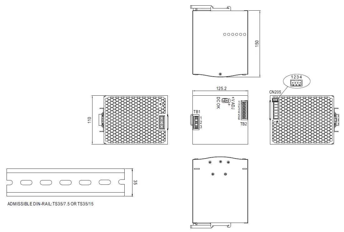
Terminal Pin No. Assignment (TB1)
| Pin No. | Assignment |
| 1 | FG |
| 2 | AC/N |
| 3 | AC/L |
Terminal Pin No. Assignment (TB2)
| Pin No. | Assignment |
| 1,2,3 | DC OUTPUT +V |
| 4,5,6 | DC OUTPUT -V |
Control Pin (CN205) : DINKLE ECH250R-04P or equivalent
| Pin No. | Assignment | Mating Housing | Wire Diameter |
| 1 | P-(Current Share) | DINKLE ESC250V-04P or equivalent (Including in the single package) | 0.081~0.517mm2 (28~20AWG) |
| 2 | P+(Current Share) | ||
| 3,4 | DC OK Relay Contact |
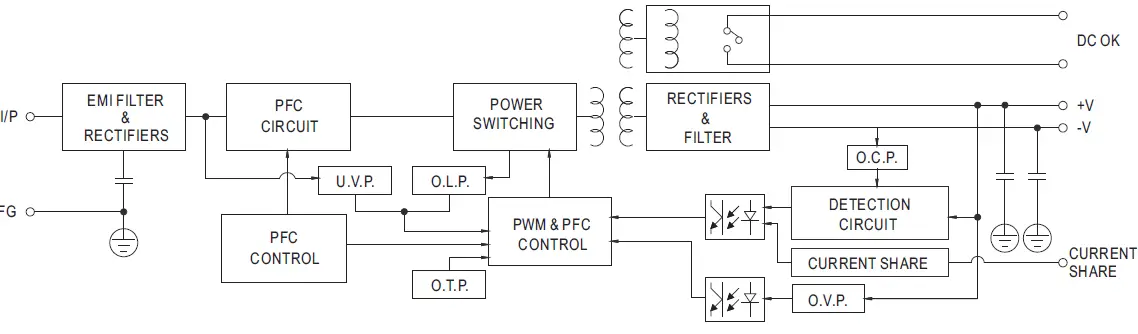
Block Diagram
 DC OK Relay Contact
| Contact Close | PSU turns on / DC OK. |
| Contact Open | PSU turns off / DC Fail. |
| Contact Ratings (max.) | 30V/1A resistive load. |
Peak Loading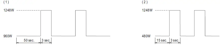 Derating Curve/Output derating VS input voltage
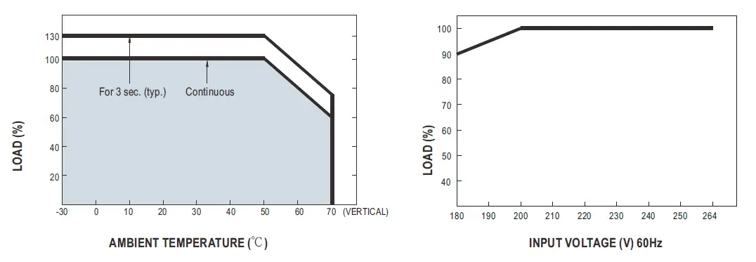
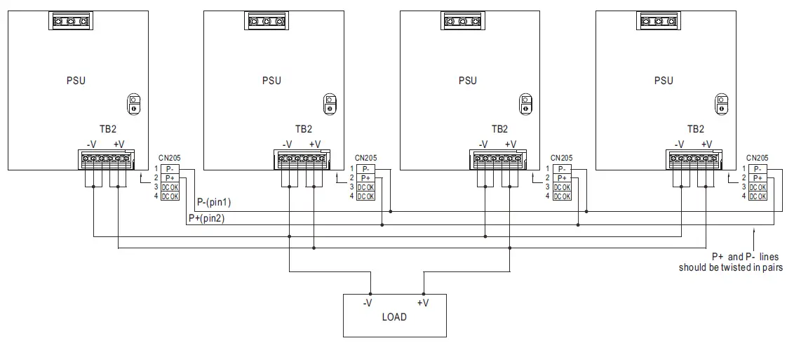
Function Manual
- Current sharing
- Parallel operation is available by connecting the units shown as below (P+,P- are connected mutually in parallel).
- Difference of output voltages among parallel units should be less than 0.2V.
- The total output current must not exceed the value determined by the following equation (Output current at parallel operation)=(The rated current per unit) x (Number of unit) x 0.9.
- In parallel operation 4 units is the maximum, please consult the manufacture for other applications.
- The power supplies should be paralleled using short and large diameter wiring and then connected to the load.
- When in parallel operation, the minimum output load should be greater than 5% of total output load. (Min. load >5% rated current per unit x number of unit)
- In parallel connection, maybe only one unit (master) operate if the total output load is less than 5% of rated load condition.
The other PSUs (slaves) may go into standby mode and their output LEDs & relays will not turn on. - Some minor noise may be heard at light load condition under parallel operation.
This is a normal phenomenon and the performance of the PSU will not be influenced.