

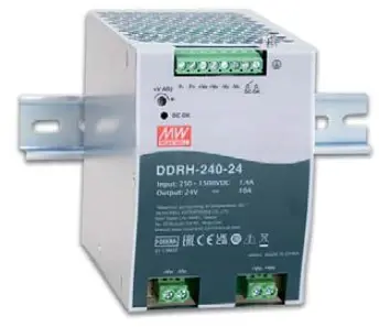
MEAN WELL DDRH-240 Series 240W Ultra Wide Input DIN Rail Type DC to DC Converter
Features
- 250 150OVdc 6:1 ultra-wide input range
- Withstand 1700Vdc surge input for 10 seconds
- 85.5mm slim width
- 4KVac /O high isolation(Reinforced isolation)
- Protections: Short circuit / Overload/ Over voltage/ Over temperature DC input under voltage / DC input reverse polarity
- Fanless design, cooling by free air convection
- Can be installed on DIN rail TS-35/7.5 or 15
- -40+80 C ultra-wide operating temperature (> +50°C derating)
- Current sharing up to 960W(3+1)
- Overvoltage category I
- Operating altitude up to 5000 meters
- DC OK relay contact
- DC Output voltage adjustable(12-15V, 24-29V, 30-36V, 48-58V)
- 3 years warranty
Applications
- Photovoltaic power generation
- Renewable Energy System
- High voltage freqency conversion
- Industrial control system
- Semiconductor fabrication equipment
- Electro-mechanical apparatus
- DC bus centralized application
- Energy storage system(ESS)
- Charging pile
- Third rail
GTIN CODE
MW Search: https://www.meanwell.com/serviceGTIN.aspx
Description
DDRH-240 series is a 250 1500Vdc high reliable ultra-high input DIN rail type DC-DC converter that can supply stable working voltage for the load. It is suitable to be mounted on TS-35/7.5 or 15 rails. The main features are as follows: easy-to-install DIN rail type, narrow width(85.5mm) in a slim design,-40~+80°C wide range operating temperature, 4KVac high isolation voltage, current sharing up to 96OW(3+1), operation at 5000m altitude, high efficiency, low ripple & noise, complete
protections and so on. DDRH-240 is compliant with BS EN/EN61000-6-2 standard regarding immunity for industrial environments. It is suitable for industrial automation, surveillance, telecommunication and can be widely deployed in the applications of new energy generation such as solar power, and windmill power generation, photovoltaic power systems, high voltage inverting application, ESS, charging piles, railway and so forth. DC bus centralized
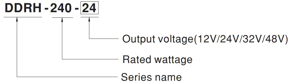
Model Encoding
SPECIFICATION
| MODEL | DDRH-240-12 | DDRH-240-24 | DDRH-240-32 | DDRH-240-48 | |||||
|
OUTPUT | DC VOLTAGE | 12V | 24V | 32V | 48V | ||||
| RATED CURRENT | 16.7A | 10A | 7.5A | 5A | |||||
| CURRENT RANGE | 0 ~ 16.7A | 0 ~ 10A | 0 ~ 7.5A | 0 ~ 5A | |||||
| RATED POWER | 200.4W | 240W | 240W | 240W | |||||
| RIPPLE & NOISE (max.) Note.2 | 120mVp-p | 240mVp-p | 240mVp-p | 300mVp-p | |||||
| VOLTAGE ADJ. RANGE | 12 ~ 15V | 24 ~ 29V | 30 ~ 36V | 48 ~ 58V | |||||
| VOLTAGE TOLERANCE Note.3 | ±1.5% | ±1.0% | ±1.0% | ±1.0% | |||||
| LINE REGULATION | ±0.5% | ±0.5% | ±0.5% | ±0.5% | |||||
| LOAD REGULATION | ±1.0% | ±0.5% | ±0.5% | ±0.5% | |||||
| EXTERNAL CAPACITANCE LOAD (Max.) | 8000μF | 5000μF | 4000μF | 2000μF | |||||
|
INPUT | VOLTAGE RANGE Note.4 | 250 ~ 1500Vdc | |||||||
| EFFICIENCY (Typ.) | 300Vdc | 85% | 87% | 87% | 87% | ||||
| 800Vdc | 88% | 90% | 90% | 90% | |||||
| 1500Vdc | 85% | 86% | 86% | 86% | |||||
| INRUSH CURRENT (max.) | COLD START 500A /1500Vdc 300A/800Vdc 120A/300Vdc | ||||||||
| EXTERNAL INPUT FUSE | 4A/1500VDC, required(Please refer to page 5 for more details) | ||||||||
| INTERNAL INPUT FUSE | 2A/1500VDC (optional) | ||||||||
|
PROTECTION | OVERLOAD | 105 ~ 135% rated output power | |||||||
| Protection type : Hiccup mode when output voltage<35%, recovers automatically after condition is removed; Constant current limiting, recovers automatically after fault condition is removed within 35% ~ 100% rated output voltage | |||||||||
| OVER VOLTAGE | 16.5 ~ 21V | 32 ~ 42V | 40 ~ 48V | 62 ~ 70V | |||||
| Protection type : Shut down o/p voltage, re-power on to recover | |||||||||
| OVER TEMPERATURE | Protection type : Hiccup mode, recovers automatically after fault condition is removed | ||||||||
| DC INPUT | REVERSE POLARITY | By internal Bridge Diode, no damage, recovers automatically after fault condition removed | |||||||
| UNDER VOLTAGE LOCKOUT | Under voltage protection range:200 ~ 230Vdc , Under voltage release range:230 ~ 245Vdc | ||||||||
| FUNCTION | DC OK SIGNAL | Relay contact rating(max.) : 30V / 1A resistive | |||||||
| CURRENT SHARING | Up to 960W(3+1 units).Please refer to the Function Manual | ||||||||
|
ENVIRONMENT | WORKING TEMP. | -40 ~ +80℃ (Refer to “Derating Curve”) | |||||||
| WORKING HUMIDITY | 20 ~ 90% RH non-condensing | ||||||||
| STORAGE TEMP., HUMIDITY | -40 ~ +80℃, 10 ~ 95% RH non-condensing | ||||||||
| TEMP. COEFFICIENT | ±0.03%/℃ (0 ~ 50℃) | ||||||||
| VIBRATION | Component: 10 ~ 500Hz, 2G 10min./1cycle, 60min. each along X, Y, Z axes; Mounting clip: Compliance to IEC60068-2-6 | ||||||||
| OPERATING ALTITUDE Note.5 | 5000m | ||||||||
| OVER VOLTAGE CATEGORY | OVCⅡ2000m, According to EN62109-1 | ||||||||
|
SAFETY & EMC (Note.7) | SAFETY STANDARDS | IEC62109-1, BS EN/EN62109-1, EAC TP TC 004 approved; Design refer to UL1741(By request) | |||||||
| WITHSTAND VOLTAGE | I/P-O/P:4KVAC I/P-FG:2KVAC O/P-FG:2KVAC O/P-DC OK:0.5KVAC | ||||||||
| ISOLATION RESISTANCE | I/P-O/P, 100M Ohms / 500VDC / 25℃/ 70% RH | ||||||||
|
EMC EMISSION | Parameter | Standard | Test Level / Note | ||||||
| Conducted | BS EN/EN55032(CISPR32) | Class A | |||||||
| Radiated | BS EN/EN55032(CISPR32) | Class A | |||||||
|
EMC IMMUNITY | BS EN/EN55035, BS EN/EN61000-6-2 | ||||||||
| Parameter | Standard | Test Level /Note | |||||||
| ESD | BS EN/EN61000-4-2 | Level 3, 8KV air; Level 2, 4KV contact, criteria A | |||||||
| Radiated Susceptibility | BS EN/EN61000-4-3 | Level 3, 10V, criteria A | |||||||
| EFT/Burest | BS EN/EN61000-4-4 | Level 3, 2KV, criteria A | |||||||
| Surge | BS EN/EN61000-4-5 | Level 4, 2KV/Vin+ ~ Vin-, 4KV/Vin~FG , criteria A | |||||||
| Conducted | BS EN/EN61000-4-6 | Level 3, 10V, criteria A | |||||||
| Magnetic Field | BS EN/EN61000-4-8 | Level 4, 30A, criteria A | |||||||
| OTHERS | MTBF | 214.2Khrs min. MIL-HDBK-217F (25℃); 1391.8Khrs min. Telcordia TR/SR-332 (Bellcore) (25℃) | |||||||
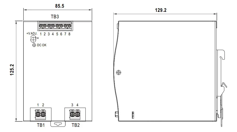
| DIMENSION | 85.5*125.2*129.2mm (W*H*D) | ||||||||
| PACKING | 0.96Kg; 8pcs/10.3Kg/1.02CUFT | ||||||||
|
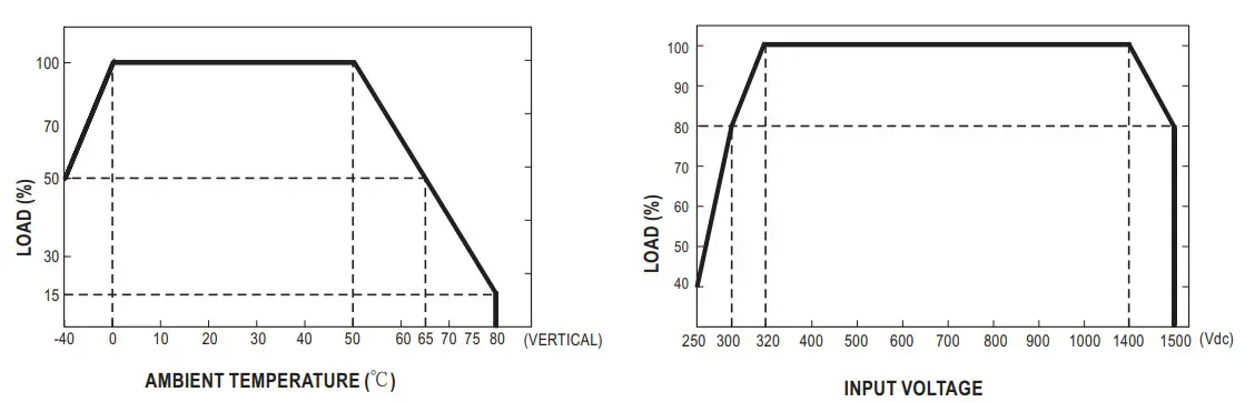
NOTE | 1. All parameters NOT specially mentioned are measured at 800Vdc input, rated load and 25℃ of ambient temperature. 2. Ripple & noise are measured at 20MHz of bandwidth by using a 12″ twisted pair-wire terminated with a 0.1μf & 47μf parallel capacitor. 3. Tolerance : includes set up tolerance, line regulation and load regulation. 4. Derating may be needed under low input voltage. Please check the derating curve for more details. 5. The ambient temperature derating of 3.5℃/1000m with fanless models and of 5℃/1000m with fan models for operating altitude higher than 2000m(6500ft). 6. Installation clearances : 40mm on top, 20mm on the bottom, 5mm on the left and right side are recommended when loaded permanently with full power. In case the adjacent device is a heat source, 15mm clearance is recommended. 7. The power supply is considered a component which will be installed into a final equipment. The final equipment must be re-confirmed that it still meets EMC directives. For guidance on how to perform these EMC tests, please refer to “EMI testing of component power supplies.” (as available on http://www.meanwell.com) ※ Product Liability Disclaimer:For detailed information, please refer to https://www.meanwell.com/serviceDisclaimer.aspx | ||||||||
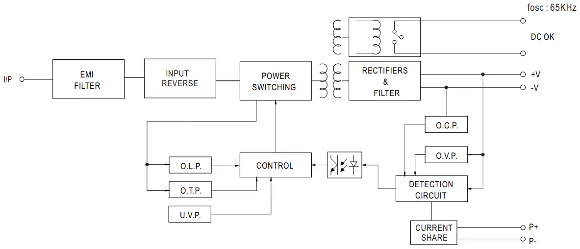
Block Diagram
- Derating Curve
- Static Characteristics


- Altitude Curve
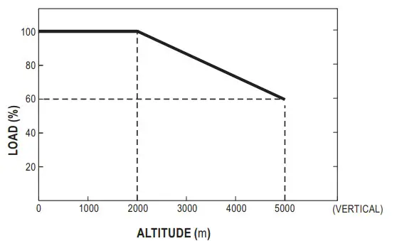
Note: Multiply by the regular power limit factor
DC OK Relay Contact
| Contact Close | PSU turns ON / DC OK. |
| Contact Open | PSU turns OFF / DC Fail. |
| Contact Ratings (max.) | 30V/1A resistive load. |
Function Manual
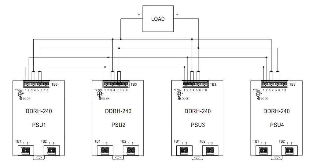
Current sharing
- Parallel operation is available by connecting the units shown as below (P+,P- are connected mutually in parallel) .
- The voltage difference among each output should be minimized that less than 0.2V is required.
- The total output current must not exceed the value determined by the following equation (Output current at parallel operation)
- =(The rated current per unit) x (Number of unit) x 0.9.
- In parallel operation 4 units is the maximum, please consult the manufacturer for other applications.
- When in parallel operation, the minimum output load should be greater than 3% of total output load.
(Min. load > 3% rated current per unit x number of unit) - In parallel operation, after overload or short circuit fault occurs, -. ) re-power on to recover.
Mechanical Specification
Terminal Pin No. Assignment (TB3)
| Pin No. | Assignment |
| 1 | P+(Current sharing) |
| 2 | P-(Current sharing) |
| 3,4 | +Vo |
| 5,6 | -Vo |
| 7,8 | DC OK Relay Contact |
External FUSE wiring instruction
External FUSE is required.FUSE specification 4A/1500Vdc.
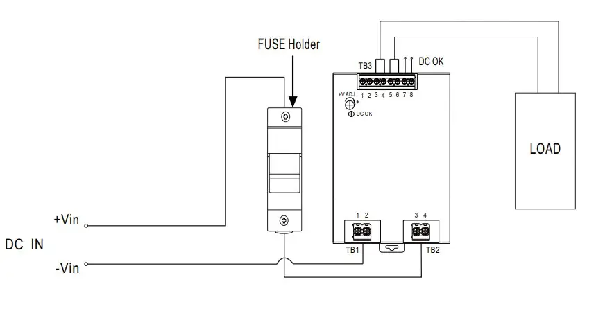
Suggested model:
| Fuse Brand | Manufacturer Part NO. | MW’s Order NO. | |
| Fuse | Fuse Holder | Fuse + Fuse Holder | |
| WalterFuse | WJ30-4 | WJ30-H | DDRH-WJ30-4-H |
| Littelfuse | SPXV-4A | LFPXV/LPXV | Not provide |
| Bussmann | PV-4A10F85L | CHPV15L85 | Not provide |
Instruction
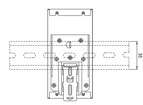
- This series fits DIN rail TS35/7.5 or TS35/15. For installation details, please refer to the Instruction manual.
- ADMISSIBLE DIN rail:TS35/7.5 OR TS35/15 (For reference only. Not included with unit.)
Installation Manual
Please refer to: http://www.meanwell.com/manual.html


