
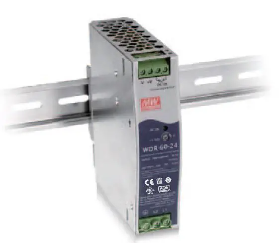
MEAN WELL WDR-60 60W Ultra Wide Input Industrial DIN Rail Power Supply
FEATURES
- 180550Vac ultra wide input for 1-phase or 2-phase
- 32mm slim width
- 4.7KVac IVO high isolation(Reinforced isolation)
- Protections: Short circuit /Overload/ Over voltage/ Over temperature
- Cooling by free air convection
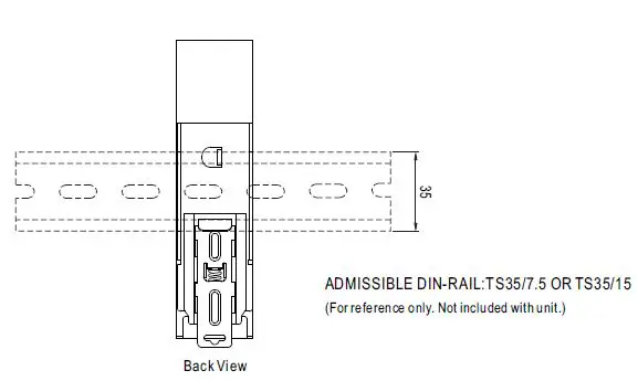
- Can be installed on DIN rail TS-35/7.5 or 15
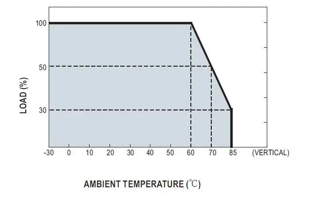
- 30+85 C ultra-wide operating temperature (>+60°C derating)
- Over voltage category I
- DC OK relay contact
- DC output voltage adjustable(+20%)
- 3 years warranty
 APPLICATIONS
- Industrial control system
- Semiconductor fabrication equipment
- Factory automation
- Electro-mechanical apparatus
Description
WDR-60 series is a 60w DIN rail power supply with ultra-wide AC input range. It is suitable to be mounted on TS-35/7.5 or TS-35/15 rails. Main features are as following: it can accept 180-550Vac ultra-wide input voltage range for single phase or 2-phase system, easy to install DIN rail type, narrow width (32mm) in slim design, -30-+85°C wide range operating temp, 4.7KVAC high isolation voltage, operation at 2000m altitude, adjustable output voltage (+20% max.), high efticiency, low ripple & noise, Complete protections and so on. WDR-60 is compliant with BS EN/EN-61000-6-2 standard regarding immunity for industrial environments. It suitable for industrial automation, surveillance, telecommunication and more applications.
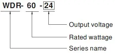
Model Encoding
SPECIFICATION
| MODEL | WDR-60-5 | WDR-60-12 | WDR-60-24 | WDR-60-48 | |||
|
OUTPUT | DC VOLTAGE | 5V | 12V | 24V | 48V | ||
| RATED CURRENT | 10A | 5A | 2.5A | 1.25A | |||
| CURRENT RANGE | 0 ~ 10A | 0 ~ 5A | 0 ~ 2.5A | 0 ~ 1.25A | |||
| RATED POWER | 50W | 60W | 60W | 60W | |||
| RIPPLE & NOISE (max.) Note.2 | 100mVp-p | 120mVp-p | 150mVp-p | 200mVp-p | |||
| VOLTAGE ADJ. RANGE | 5 ~ 6V | 12 ~ 15V | 24 ~ 29V | 48 ~ 57V | |||
| VOLTAGE TOLERANCE Note.3 | ±2% | ±1.5% | ±1.0% | ±1.0% | |||
| LINE REGULATION | ±0.5% | ±0.5% | ±0.5% | ±0.5% | |||
| LOAD REGULATION | ±1.5% | ±0.5% | ±0.5% | ±0.5% | |||
| SETUP, RISE, HOLD UP TIME | 1000ms, 70ms, 20ms/400Vac 2000ms, 70ms, 10ms/230Vac at full load | ||||||
|
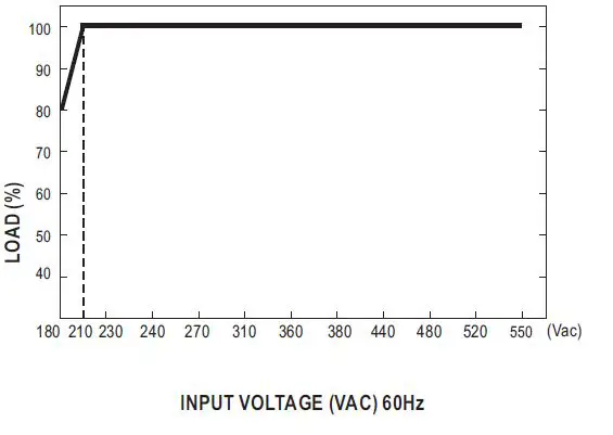
INPUT | VOLTAGE RANGE Note.4 | 180 ~ 550Vac or 254 ~ 780Vdc | |||||
| FREQUENCY RANGE | 47 ~ 63Hz | ||||||
| EFFICIENCY (Typ.) | 83.5% / 400Vac | 86.5% / 400Vac | 89% / 400Vac | 90.5% / 400Vac | |||
| AC CURRENT | 0.4A/400Vac 0.7A/230Vac | ||||||
| INRUSH CURRENT (max.) | COLD START 50A /400Vac 30A/230Vac | ||||||
| LEAKAGE CURRENT | <2mA / 530Vac | ||||||
|
PROTECTION | OVERLOAD | 105 ~ 135% rated output power | |||||
| Hiccup mode when output voltage <50%, recovers automatically after fault condition is removed Constant current limiting within 50% ~100% rated output voltage, recovers automatically after fault condition is removed | |||||||
| OVER VOLTAGE | 6.2 ~ 7.2V | 16 ~ 18V | 31 ~ 37V | 58 ~ 60.5V | |||
| Protection type : Shut down o/p voltage, re-power on to recover | |||||||
| OVER TEMPERATURE | Protection type : Shut down o/p voltage, re-power on to recover | ||||||
| FUNCTION | DC OK SIGNAL | Relay contact rating(max.) : 30V / 1A resistive | |||||
|
ENVIRONMENT | WORKING TEMP. | -30 ~ +85℃ (Refer to “Derating Curve”) | |||||
| WORKING HUMIDITY | 20 ~ 90% RH non-condensing | ||||||
| STORAGE TEMP. | -40 ~ +85℃ | ||||||
| TEMP. COEFFICIENT | ±0.03%/℃ (0 ~ 60℃) | ||||||
| VIBRATION | Component: 10 ~ 500Hz, 2G 10min./1cycle, 60min. each along X, Y, Z axes; Mounting clip: Compliance to IEC60068-2-6 | ||||||
| OPERATING ALTITUDE Note.5 | 2000 meters | ||||||
| OVER VOLTAGE CATEGORY | Ⅲ; According to EN61558, EN50178, EN60664-1, EN62477-1, EN60204-1; altitude up to 2000 meters | ||||||
|
SAFETY & EMC (Note 7) | SAFETY STANDARDS | UL61010, BS EN/EN61558-2-16, AS/NZS 62368.1, EAC TP TC 004 approved; design refer to GL and BS EN/EN60204-1(By request) | |||||
| WITHSTAND VOLTAGE | I/P-O/P:4.7KVAC I/P-FG:2.5KVAC O/P-FG:0.5KVAC O/P-DC OK:0.5KVAC | ||||||
| ISOLATION RESISTANCE | I/P-O/P, I/P-FG, O/P-FG:100M Ohms / 500VDC / 25℃/ 70% RH | ||||||
|
EMC EMISSION | Parameter | Standard | Test Level / Note | ||||
| Conducted | BS EN/EN55032(CISPR32) | Class B | |||||
| Radiated | BS EN/EN55032(CISPR32) | Class B | |||||
| Harmonic Current | BS EN/EN61000-3-2 | Class A | |||||
| Voltage Flicker | BS EN/EN61000-3-3 | ——- | |||||
|
EMC IMMUNITY | BS EN/EN55024, BS EN/EN55035, BS EN/EN61000-6-2, BS EN/EN61204-3 | ||||||
| Parameter | Standard | Test Level /Note | |||||
| ESD | BS EN/EN61000-4-2 | Level 3, 8KV air; Level 2, 4KV contact, criteria A | |||||
| Radiated Susceptibility | BS EN/EN61000-4-3 | Level 3, 10V/m, criteria A | |||||
| EFT Bursts | BS EN/EN61000-4-4 | Level 3, 2KV/5KHz, criteria A | |||||
| Surge | BS EN/EN61000-4-5 | Level 4, 2KV/Line-Line, 4KV/Line-Earth, criteria A | |||||
| Conducted | BS EN/EN61000-4-6 | Level 3, 10V, criteria A | |||||
| Magnetic Field | BS EN/EN61000-4-8 | Level 4, 30A/m, criteria A | |||||
| Voltage Dips and interruptions | BS EN/EN61000-4-11 | >95% dip 0.5 periods, 30% dip 25 periods, >95% interruptions 250 periods | |||||
| OTHERS | MTBF | 313.68K hrs min. MIL-HDBK-217F (25℃) | |||||
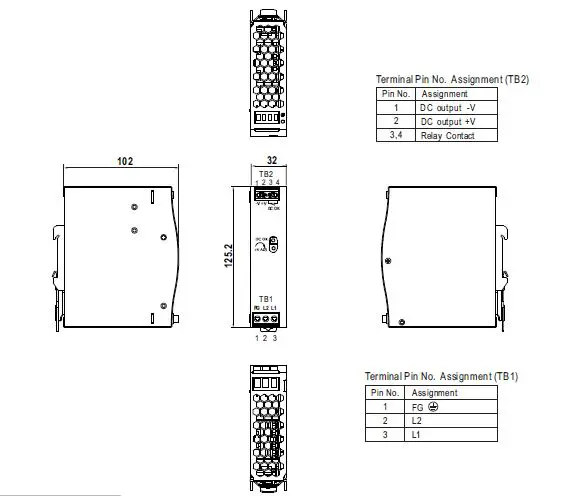
| DIMENSION | 32*125.2*102mm (W*H*D) | ||||||
| PACKING | 0.45Kg; 28pcs/13.6Kg/1.24CUFT | ||||||
|
NOTE | 1. All parameters NOT specially mentioned are measured at 400VAC input, rated load and 25℃ of ambient temperature. 2. Ripple & noise are measured at 20MHz of bandwidth by using a 12″ twisted pair-wire terminated with a 0.1μf & 47μf parallel capacitor. 3. Tolerance : includes set up tolerance, line regulation and load regulation. 4. Derating may be needed under low input voltage. Please check the derating curve for more details. 5. The ambient temperature derating of 3.5℃/1000m with fanless models and of 5℃/1000m with fan models for operating altitude higher than 2000m(6500ft). 6. Installation clearances : 40mm on top, 20mm on the bottom, 5mm on the left and right side are recommended when loaded permanently with full power. In case the adjacent device is a heat source, 15mm clearance is recommended. 7. The power supply is considered a component which will be installed into a final equipment. The final equipment must be re-confirmed that it still meets EMC directives. For guidance on how to perform these EMC tests, please refer to “EMI testing of component power supplies.” (as available on http://www.meanwell.com) ※ Product Liability Disclaimer: For detailed information, please refer to https://www.meanwell.com/serviceDisclaimer.aspx | ||||||
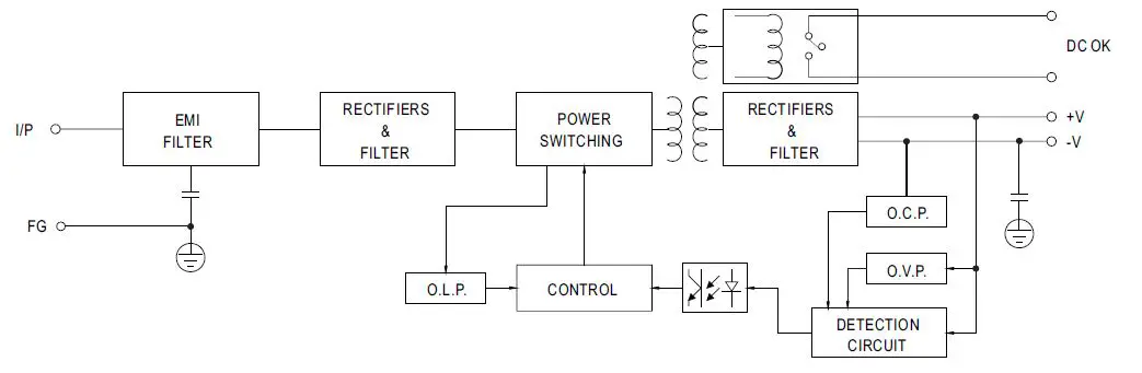
BLOCK DIAGRAM
DERATING CURVE
STATIC CHARACTERISTICS
DC OK RELAY CONTACT
| Contact Close | PSU turns ON / DC OK. |
| Contact Open | PSU turns OFF / DC Fail. |
| Contact Ratings (max.) | 30V/1A resistive load. |
MECHANICAL SPECIFICATION
INSTALLATION INSTRUCTION
INSTALLATION MANUAL
Please refer to : http://www.meanwell.com/manual.html