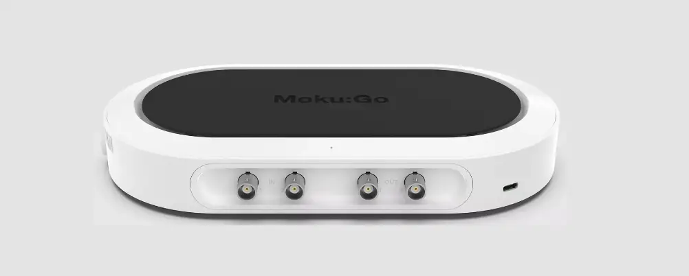
LIQUID INSTRUMENTS Moku:Go PID Controller
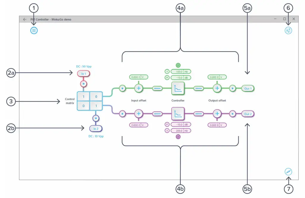
User Interface
| ID | Description |
| 1 | Main menu |
| 2a | Input configuration for Channel 1 |
| 2b | Input configuration for Channel 2 |
| 3 | Control matrix |
| 4a | Configuration for PID Controller 1 |
| 4b | Configuration for PID Controller 2 |
| 5a | Output switch for Channel 1 |
| 5b | Output switch for Channel 2 |
| 6 | Settings |
| 7 | Enable/disable the oscilloscope view |
The main menu can be accessed by pressing the icon![]() on the top-left corner.
on the top-left corner.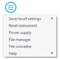
This menu provides the following options:
| Options | Shortcuts | Description |
| Save/recall settings: | ||
| Save instrument state | Ctrl+S | Save the current instrument settings. |
| Load instrument state | Ctrl+O | Load last saved instrument settings. |
| Show current sate | Show the current instrument settings. | |
| Reset instrument | Ctrl+R | Reset the instrument to its default state. |
| Power supply | Access power supply control window.* | |
| File manager | Open file manager tool.** | |
| File converter | Open file converter tool.** | |
| Help | ||
| Liquid Instruments website | Access Liquid Instruments website. | |
| Shortcuts list | Ctrl+H | Show Moku:Go app shortcuts list. |
| Manual | F1 | Access instrument manual. |
| Report an issue | Report bug to Liquid Instruments. | |
| About | Show app version, check update, or license information. |
Power supply is available on Moku:Go M1 and M2 models. Detailed information about power supply can be found in Moku:Go power
supply manual.
Detailed information about the file manager and file converter can be found toward the end of this user manual
Input Configuration
The input configuration can be accessed by tapping the![]() or
or![]() icon, allowing you to adjust the coupling, and input range for each input channel.
icon, allowing you to adjust the coupling, and input range for each input channel.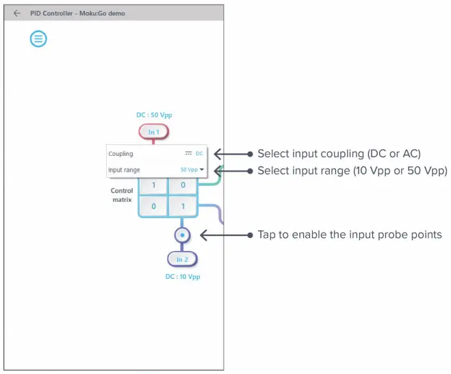
Details about the probe points can be found in the Probe Points section.
Control Matrix
The control matrix combines, rescales, and redistributes the input signal to the two independent PID controllers. The output vector is the product of the control matrix multiplied by the input vector.
where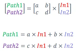
For example, a control matrix of ![]() equally combines the Input 1 and Input 2 to the top Path1 (PID Controller 1); multiples Input 2 by a factor of two, and then sends it to the bottom Path2 (PID Controller 2).
equally combines the Input 1 and Input 2 to the top Path1 (PID Controller 1); multiples Input 2 by a factor of two, and then sends it to the bottom Path2 (PID Controller 2).
The value of each element in the control matrix can be set between -20 to +20 with 0.1 increments when the absolute value is less than 10, or 1 increment when the absolute value is between 10 and 20. Tap the element to adjust the value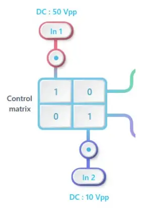
PID Controller
The two independent, fully real-time configurable PID controller paths follow the control matrix in the block diagram, represented in green and purple for controller 1 and 2, respectively.
User Interface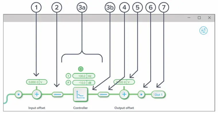
| ID | Function | Description |
| 1 | Input offset | Click to adjust the input offset (-2.5 to +2.5 V). |
| 2 | Input switch | Click to zero the input signal. |
| 3a | Quick PID control | Click to enable/disable controllers and adjust the parameters. Not available in advanced mode. |
| 3b | Controller view | Click to open full controller view. |
| 4 | Output switch | Click to zero the output signal. |
| 5 | Output offset | Click to adjust the output offset (-2.5 to +2.5 V). |
| 6 | Output probe | Click to enable/disable the output probe point. See Probe Points section for details. |
| 7 | Moku:Go output switch | Click to enable/disable the Moku:Go’s output. |
Input / Output Switches
 Closed/Enable
 Open/disable
Controller (Basic Mode)
Controller Interface
Tap![]() the icon to open the full controller view.
the icon to open the full controller view.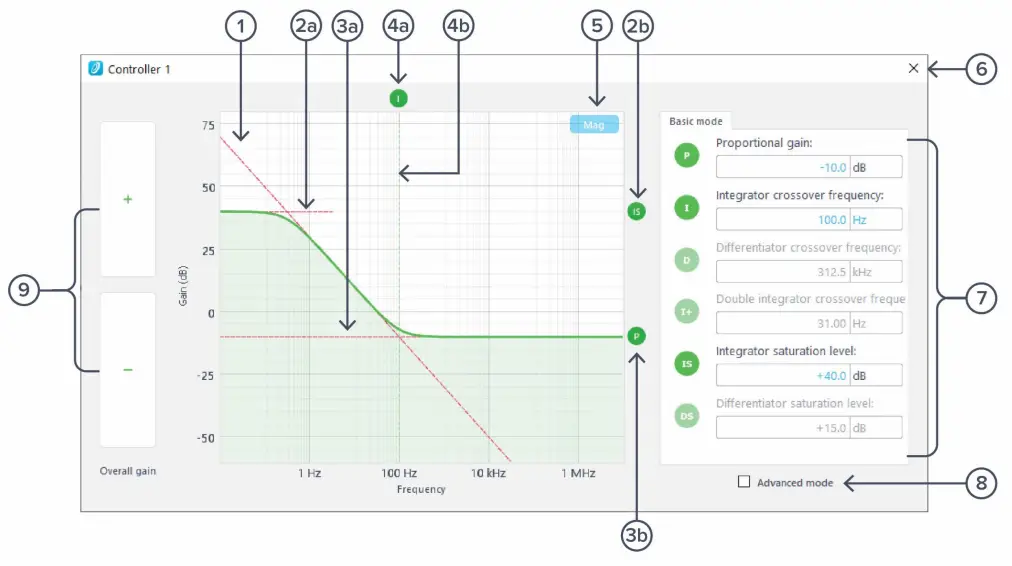
| ID | Function | Description |
| 1 | Design cursor 1 | Cursor for Integrator (I) setting. |
| 2a | Design cursor 2 | Cursor for Integrator Saturation (IS) level. |
| 2b | Cursor 2 indicator | Drag to adjust cursor 2 (IS) level. |
| 3a | Design cursor 3 | Cursor for Proportional (P) gain. |
| 3b | Cursor 3 indicator | Drag to adjust curser 3 (P) level. |
| 4a | Cursor 4 indicator | Drag to adjust curser 4 (I) frequency. |
| 4b | Design cursor 4 | Cursor for I crossover frequency. |
| 5 | Display toggle | Toggle between magnitude and phase response curve. |
| 6 | Close controller view | Click to close the full controller view. |
| 7 | PID control | Turn on/off individual controller, and adjust the parameters. |
| 8 | Advanced mode | Click to switch to the advanced mode. |
| 9 | Overall gain control | Click to adjust overall gain of the controller. |
PID Response Plot
The PID Response Plot provides an interactive representation (gain as a function of frequency) of the controller.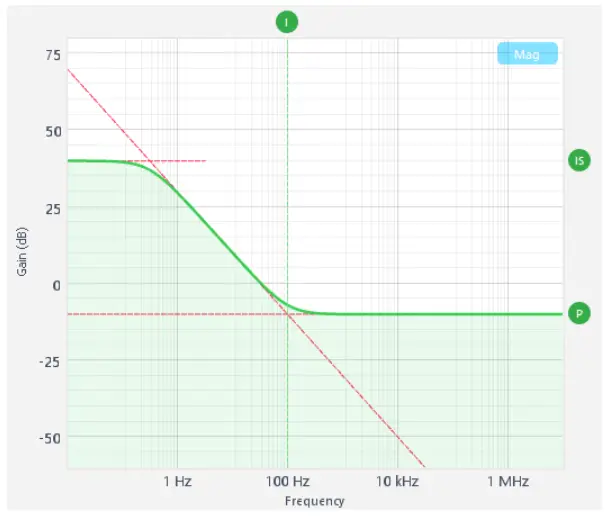
The green/purple solid curve represents the active response curve for PID Controller 1 and 2, respectively.
The green/purple dashed vertical lines (○4 ) represent the cursors crossover frequencies, and/or unity gain frequencies for PID Controller 1 and 2, respectively.
The red dashed lines (○1 ,○2 ,and ○3 ) represent the cursors for each controller.
Letter Abbreviations for Controllers
| ID | Description | ID | Description |
| P | Proportional gain | I+ | Double integrator crossover frequency |
| I | Integrator crossover frequency | IS | Integrator saturation level |
| D | Differentiator | DS | Differentiator saturation level |
List of Configurable Parameters in Basic Mode
| Parameters | Range |
| Overall gain | ± 60 dB |
| Proportional gain | ± 60 dB |
| Integrator crossover frequency | 312.5 mHz to 31.25 kHz |
| Differentiator crossover frequency | 3.125 Hz to 312.5 kHz |
| Integrator saturation level | ± 60 dB or limited by the crossover frequency/proportional gain |
| Differentiator saturation level | ± 60 dB or limited by the crossover frequency/proportional gain |
Controller (Advanced Mode)
In Advanced Mode, users can build fully customized controllers with two independent sections (A and B), and six adjustable parameters in each section. Tap the Advanced Mode button in the full controller view to switch to the Advanced Mode.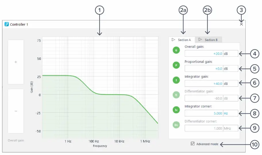
| ID | Function | Description |
| 1 | Frequency response | Frequency response of the controller. |
| 2a | Section A pane | Click to select and configure Section A. |
| 2b | Section B pane | Click to select and configure Section B. |
| 3 | Close controller view | Click to close the full controller view. |
| 4 | Overall gain | Click to adjust the overall gain. |
| 5 | Proportional panel | Click the icon to enable/disable proportional path. Click the number to adjust the gain. |
| 6 | Integrator panel | Click the icon to enable/disable integrator path. Click the number to adjust the gain. |
| 7 | Differentiator panel | Click the icon to enable/disable differential path. Click the number to adjust the gain. |
| 8 | Integrator saturation corner frequency | Click the icon to enable/disable integrator saturation path. Click the number to adjust the frequency. |
| 9 | Differentiator saturation corner frequency | Click the icon to enable/disable differentiator saturation path. Click the number to adjust the frequency. |
| 10 | Basic mode | Tap to switch to the basic mode. |
Quick PID Control
This panel allows user quickly to view, enable, disable, and adjust the PID controller without open the controller interface. It is only available in basic PID mode.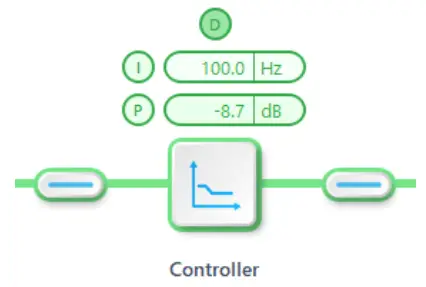
Click the P, I, or D icon to disable active controller path.
Click the shaded icon (i.e. ![]() ) to enable the path.
) to enable the path.
Click the active controller path icon (i.e.![]() ) to enter the value.
) to enter the value.
Probe Points
Moku:Go’s PID controller has an integrated oscilloscope that can be used to probe the signal at the input, pre-PID, and output stages. The probe points can be added by tapping ![]() the icon.
the icon.
Oscilloscope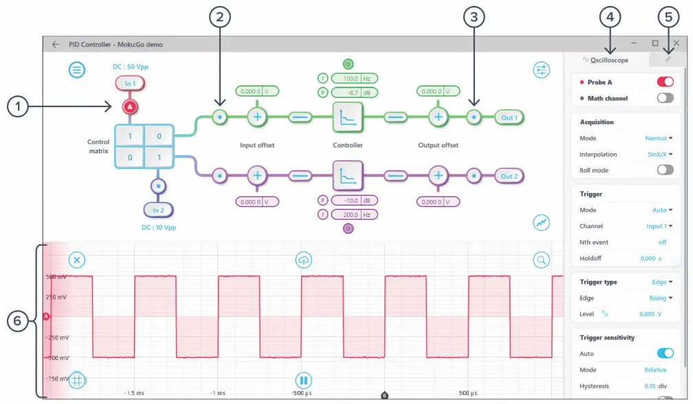
| ID | Parameter | Description |
| 1 | Input probe point | Click to place the probe point at input. |
| 2 | Pre-PID probe point | Click to place the probe after the control matrix. |
| 3 | Output probe point | Click to place the probe at output. |
| 4 | Oscilloscope settings* | Additional settings for built-in oscilloscope. |
| 5 | Measurement* | Measurement function for built-in oscilloscope. |
| 6 | Oscilloscope* | Signal display area for oscilloscope. |
*Detailed instructions for the oscilloscope instrument can be found in Moku:Go oscilloscope manual.
Additional Tools
Moku:Go’s app has two built-in file management tools: file manager and file converter. The file manager allows users to download the saved data from Moku:Go to a local computer, with optional file format conversion. The file converter converts the Moku:Go’s binary (.li) format on the local computer to either .csv, .mat, or .npy format.
File Manager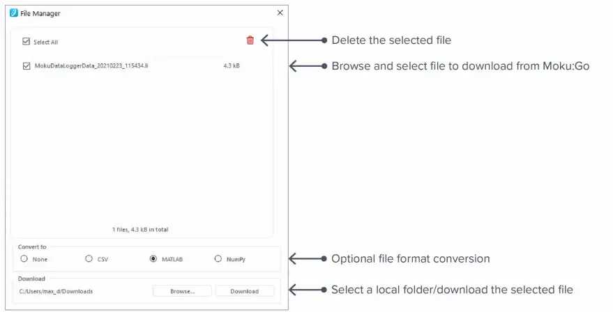
Once a file is transferred to the local computer, a ![]() icon shows up next to the file.
icon shows up next to the file.
File Converter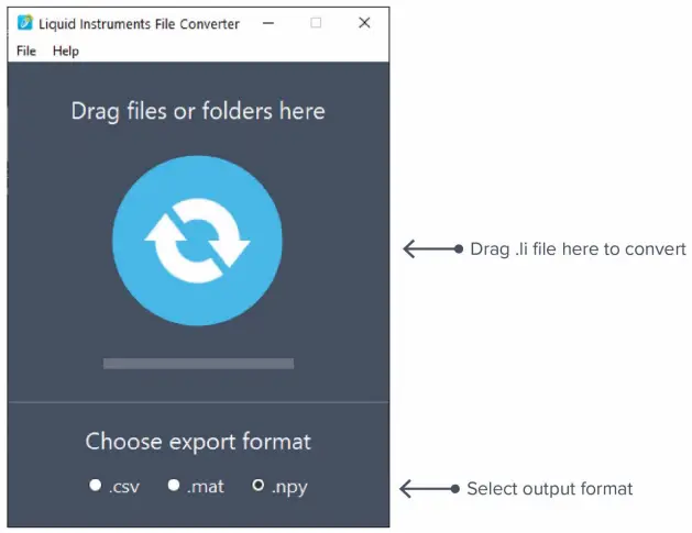
The converted file is saved in the same folder as the original file.
Liquid Instruments File Converter has the following menu options:
| Options | Shortcut | Description |
| File | ||
| · Open file | Ctrl+O | Select a .li file to convert |
| · Open folder | Ctrl+Shift+O | Select a folder to convert |
| · Exit | Close the file converter window | |
| Help | ||
| · Liquid Instruments website | Access Liquid Instruments website | |
| · Report an issue | Report bug to Liquid Instruments | |
| · About | Show app version, check update, or license information |
Power Supply
Moku:Go Power supply is available on M1 and M2 models. M1 features a 2-channel power supply, while M2 features a 4-channel power supply. The power supply control window can be accessed in all instruments under the main menu.
The power supply operates in two modes: constant voltage (CV) or constant current (CC) mode. For each channel, the user can set a current and voltage limit for the output. Once a load is connected, the power supply operates either at the set current or set voltage, whichever comes first. If the power supply is voltage limited, it operates in the CV mode. If the power supply is current limited, it operates in the CC mode.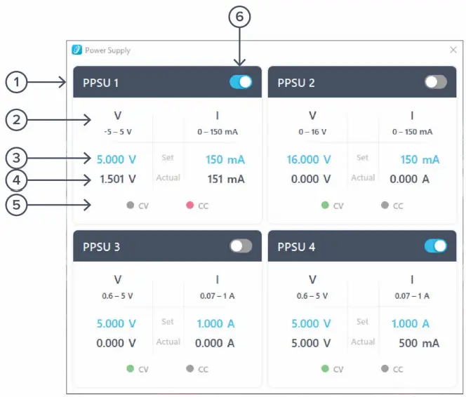
| ID | Function | Description |
| 1 | Channel name | Identifies the power supply being controlled. |
| 2 | Channel range | Indicates the voltage/current range of the channel. |
| 3 | Set value | Click the blue numbers to set the voltage and current limit. |
| 4 | Readback numbers | Voltage and current readback from the power supply, the actual voltage and current being supplied to the external load. |
| 5 | Mode indicator | Indicates if the power supply is in CV (green) or CC (red) mode. |
| 6 | On/Off Toggle | Click to turn the power supply on and off. |
Ensure Moku:Go is fully updated. For the latest information:
www.liquidinstruments.com