LIQUID INSTRUMENTS Moku: Go Digital Filter Box

Product Information
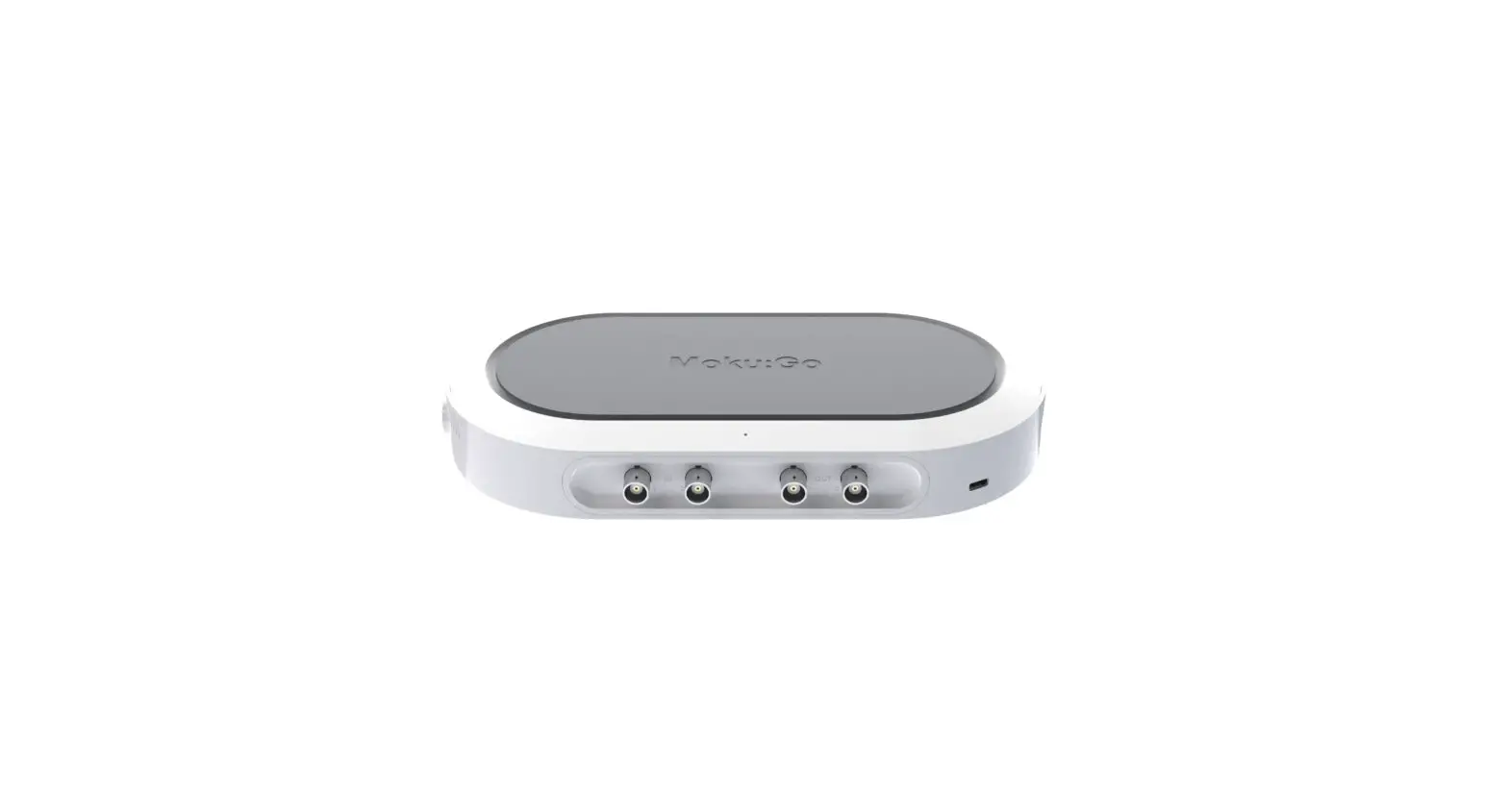
Digital Filter Box Moku
The Moku: Go Digital Filter Box is a device that allows users to design and generate different types of infinite impulse response filters with sampling rates of 61.035 kHz, 488.28 kHz and 3.9063 MHz. It offers four filter shapes, namely low pass, high pass, band pass, and band stop filter shapes, with up to eight fully configurable types including Butterworth, Chebyshev, and Elliptic.
The device features a user interface with different configuration options:
User Interface
- Main menu
- Input configuration for Channel 1 and 2
- Control matrix
- Configuration for filters 1 and 2
- Output switch for Channel 1 and 2
- Enable/disable the Oscilloscope view
- Enable/disable the Data Logger view
Main Menu
The main menu can be accessed by pressing the icon in the top-left corner. The following options are available:
- Search for Moku devices.
- Switch instruments on this Moku: Go.
- Save/recall settings: Ctrl+S, Ctrl+O.
- Show the current instrument settings.
- Reset the instrument to its default state: Ctrl+R.
- Access the Power Supply control window.*
- Open the file manager tool.**
- Open file converter tool.**
- Help: Ctrl+H, F1.
Product Usage Instructions
Before using the device, ensure that Moku: Go is fully updated. For the latest information, visit liquidinstruments.com.
To use the Digital Filter Box Moku: Go, follow these steps:
- Access the main menu by pressing the icon on the top-left corner of the user interface.
- Select the desired filter shape from the configuration options available.
- Configure the filter characteristics according to your needs, including sampling rates, filter types, filter orders, ripples, and coefficient quantization.
- If necessary, you can create a custom filter by selecting the “Custom filter” option and providing the details in the “Custom filter details” section.
- Select the output switches for Channel 1 and 2 as needed.
- You can enable or disable the Oscilloscope view and Data Logger view as needed.
For more information on using the device’s additional tools such as the Power Supply control window, file manager tool, and file converter tool, refer to the product user manual.
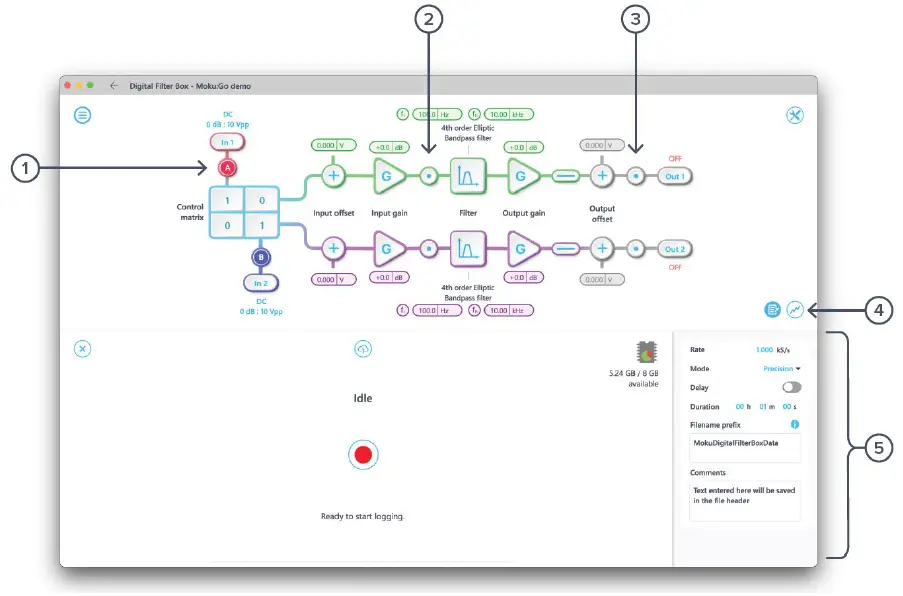
With the Moku:Go Digital Filter Box, you can interactively design and generate different types of infinite impulse response filters with sampling rates of 61.035 kHz, 488.28 kHz and 3.9063 MHz. Select between low pass, high pass, band pass, and band stop filter shapes with up to eight fully configurable types including Butterworth, Chebyshev, and Elliptic.
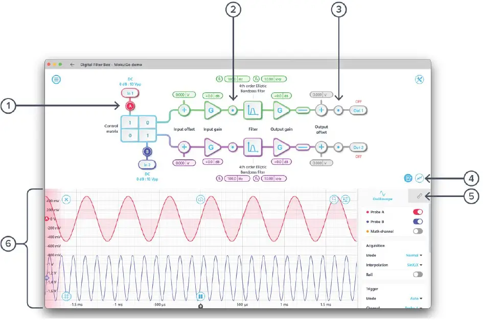
User interface
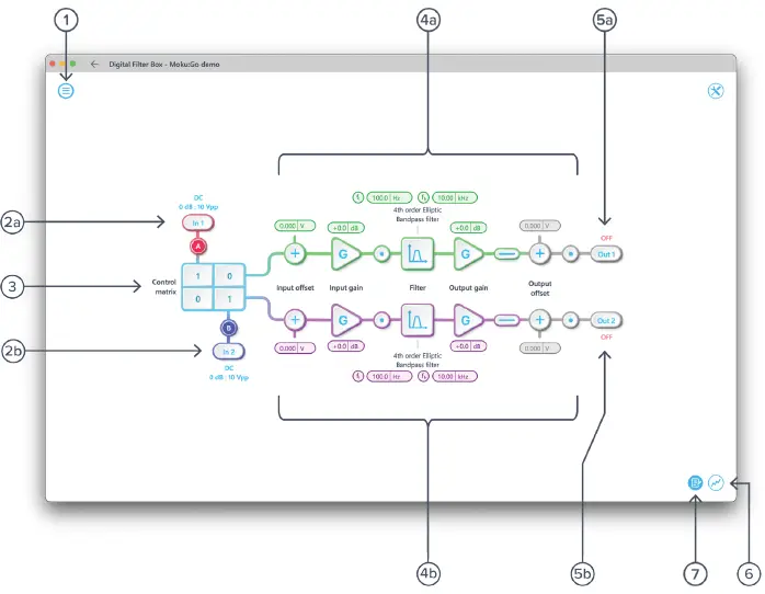
| ID | Description |
| 1 | Main menu |
| 2a | Input configuration for Channel 1 |
| 2b | Input configuration for Channel 2 |
| 3 | Control matrix |
| 4a | Configuration for filter 1 |
| 4b | Configuration for filter 2 |
| 5a | Output switch for Channel 1 |
| 5b | Output switch for Channel 2 |
| 6 | Enable/disable the Oscilloscope view |
| 7 | Enable/disable the Data Logger view |
The main menu can be accessed by pressing the![]() icon on the top-left corner.
icon on the top-left corner.
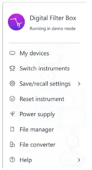
| Options | Shortcuts | Description |
| My devices | Search for Moku devices. | |
| Switch instruments | Switch instruments on this Moku:Go. | |
| Save/recall settings: | ||
| · Save instrument state | Ctrl+S | Save the current instrument settings. |
| · Load instrument state | Ctrl+O | Load last saved instrument settings. |
| · Show current sate | Show the current instrument settings. | |
| Reset instrument | Ctrl+R | Reset the instrument to its default state. |
| Power Supply | Access Power Supply control window.* | |
| File manager | Open file manager tool.** | |
| File converter | Open file converter tool.** | |
| Help | ||
| · Liquid Instruments website | Access Liquid Instruments website. | |
| · Shortcuts list | Ctrl+H | Show Moku:Go app shortcuts list. |
| · Manual | F1 | Access instrument manual. |
| · Report an issue | Report bug to Liquid Instruments. | |
| · About | Show app version, check for updates, or show license information. |
- Power Supply is available on Moku:Go M1 and M2 models. Detailed information about Power Supply can be found in the Moku:Go Power Supply section toward the end of this user manual.
- Detailed information about the file manager and file converter can be found toward the end of this user manual.
Input configuration
The input configuration can be accessed by clicking the![]() or
or![]() icon, allowing you to adjust the coupling and input attenuation (and therefore voltage range) for each input channel.
icon, allowing you to adjust the coupling and input attenuation (and therefore voltage range) for each input channel.
Details about the probe points can be found in the Probe Points section.
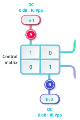
Control matrix
The control matrix combines, rescales, and redistributes the input signal to the two independent filters. The output vector is the product of the control matrix multiplied by the input vector.
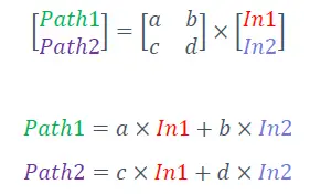
For example, a control matrix![]() equally combines Input 1 and Input 2 to the top Path1 (filter 1), multiples Input 2 by a factor of two, and then sends it to the bottom Path2 (filter 2). The value of each element in the control matrix can be set between -20 to +20 with 0.1 increments when the absolute value is less than 10, or 1 increment when the absolute value is between 10 and 20. Click the element to adjust the value.
equally combines Input 1 and Input 2 to the top Path1 (filter 1), multiples Input 2 by a factor of two, and then sends it to the bottom Path2 (filter 2). The value of each element in the control matrix can be set between -20 to +20 with 0.1 increments when the absolute value is less than 10, or 1 increment when the absolute value is between 10 and 20. Click the element to adjust the value.
Digital filters
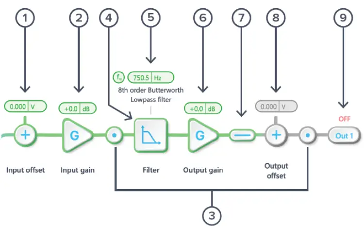
The two independent, real-time configurable digital IIR filter paths follow the control matrix in the block diagram, represented in green and purple for filters 1 and 2, respectively.
User interface
| ID | Parameter | Description |
| 1 | Input offset | Click to adjust the input offset (-2.5 to +2.5 V). |
| 2 | Input gain | Click to adjust the input gain (-40 to 40 dB). |
| 3 | Probe points | Click to enable/disable the probe points. See Probe Points section for details. |
| 4 | Digital filter | Click to view and configure the digital filter builder. |
| 5 | Quick filter control | Click or slide to quickly adjust the filter settings. |
| 6 | Output gain | Click to adjust the output gain (-40 to 40 dB). |
| 7 | Output switch | Click to zero the filter output. |
| 8 | Output offset | Click to adjust the output offset (-2.5 to +2.5 V). |
| 9 | DAC switch | Click to enable/disable the Moku:Go DAC output. |
Configure IIR filter characteristics
Detailed filter interface
Click the![]() icon to open the full filter view.
icon to open the full filter view.
| ID | Parameter | Description |
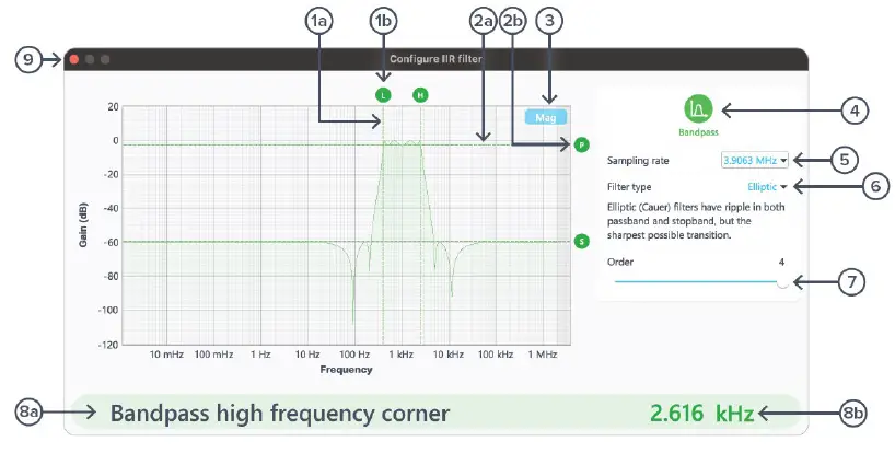
| 1a | Frequency (horizontal) cursor | Cursor for corner frequency. |
| 1b | Cursor reading | Reading for frequency cursor. Drag to adjust the corner frequency. Click to select and manually enter the corner frequency in 8b. |
| 2a | Gain (vertical) cursor | Cursor for ripple/gain/attenuation level. |
| 2b | Cursor handle | Short name and handle for gain cursor. Drag to adjust the gain/ripple level. Click to select and manually enter passband ripple in 8b. |
| 3 | Display toggle | Toggle between magnitude and phase response curve. |
| 4 | Filter shape selection | Click to select between low pass, high pass, band pass, band stop, and custom filters. |
| 5 | Sampling rate | Click to select between 3.9063 MHz, 488.28 kHz, or 61.035 kHz. |
| 6 | Filter type selection | Click to select between Butterworth, Chebyshev I/II, Elliptic, Bessel, Gaussian, Cascaded or Legendre filters. When selected, a short description of the filter type will be given below. |
| 7 | Filter order | Slide to adjust filter orders. |
| 8a | Active configurable parameter | Name of the active configurable parameter. |
| 8b | Parameter value | Click to manually enter the active configurable parameter value. |
| 9 | Save and close | Click to save and close the filter builder. |
Filter shapes
The shape of the filter can be selected by clicking the 4 button. There are four pre-defined filter shapes and a fully customizable filter option.

Sampling rates
Users can select between 3.9063 MHz, 488.28 kHz, or 61.035 kHz of output sampling rate based on the desired corner frequencies. The following table summarizes the lower and upper bounds for each shape of pre-defined filters with different sampling rates:
| Shape | Sampling Rate | Minimum corner frequency | Maximum corner frequency |
| Lowpass | 61.035 kHz | 11.73 mHz | 27.47 kHz |
| 488.28 kHz | 93.81 mHz | 219.7 kHz | |
| 3.9063 MHz | 750.5 mHz | 1.758 MHz | |
| Highpass | 61.035 kHz | 144.7 mHz | 27.47 kHz |
| 488.28 kHz | 1.158 Hz | 219.7 kHz | |
| 3.9063 MHz | 9.263 Hz | 1.758 MHz | |
| Bandpass | 61.035 kHz | 610.4 mHz | 27.47 kHz |
| 488.28 kHz | 4.883 Hz | 219.7 kHz | |
| 3.9063 MHz | 39.06 Hz | 1.758 MHz | |
| Bandstop | 61.035 kHz | 11.73 mHz | 27.47 kHz |
| 488.28 kHz | 93.81 mHz | 219.7 kHz | |
| 3.9063 MHz | 750.5 mHz | 1.758 MHz |
Filter types
The type of filter can be selected by pressing the 6 button. There are seven pre-defined filter types with user-selectable filter orders from 2 up to 8, depending on the filter shapes.
| Filter types | Description |
| Butterworth | Butterworth filters have a maximally flat passband and a monotonic frequency response. |
| Chebyshev I | Chebyshev I filters have ripple in the passband but a sharper transition than Butterworth filters. |
| Chebyshev II | Chebyshev II filters have ripple in the stopband but a sharper transition than Butterworth filters. |
| Elliptic | Elliptic (Cauer) filters have ripple in both passband and stopband, but the sharpest possible transition. |
| Cascaded | Cascaded first-order filters have zero overshoot in the time domain. |
| Bessel | Bessel filters have a maximally flat group and phase delay in the passband, thus preserving the wave shape of passed signals. |
| Gaussian | Gaussian filters have the minimum possible group delay, and a step response with no overshoot and minimum rise and fall time. |
| Legendre | Legendre (Optimum L) filters have the sharpest possible transition while maintaining a monotonic frequency response. |
Filter orders
For single sided filters, the order of the filter can be set to 2, 4, 6, or 8. For double sided filters, the order of the filter can be 2 or 4.
Ripples
Chebyshev I, II, and Elliptic filters have ripples on either passband, stopband, or both. The following table summarize the adjustable range for the passband and stopband ripples for these filter types.
| Filter types | Passband ripple | Stopband ripple |
| Chebyshev I | 0.1 dB to 10.0 dB with 0.1 dB increment | N/A. |
| Chebyshev II | N/A | 10.0 dB to 100.0 dB with 1 dB increment. |
| Elliptic | 0.1 dB to 10.0 dB with 0.1 dB increment | 10.0 dB to 100.0 dB with 1 dB increment. |
Coefficient quantization
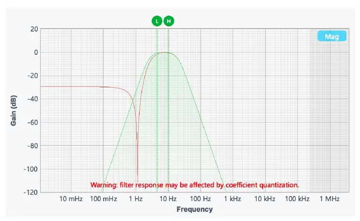
Due to the limited precision with which a coefficient can be digitally represented, quantization error is pronounced at certain IIR filter settings. A red coefficient quantization warning may appear on the bottom of the response plot with a red trace in the transfer function showing the closest achievable filter response to the ideal value in green.
Custom filter
Additionally, you can upload filter coefficients for a custom filter type from the clipboard or a local file. Click the![]() icon to see explanation of the coefficients and file format.
icon to see explanation of the coefficients and file format.

Custom filter details
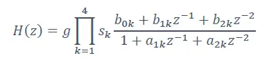
The Moku:Go Digital Filter Box implements infinite impulse response (IIR) filters using four cascaded Direct Form I second-order stages with a final output gain stage. The total transfer function can be written:
To specify a filter, you must supply a text file containing the filter coefficients. The file should have six coefficients per line, with each line representing a single stage. If output scaling is required, this should be given on the first line:
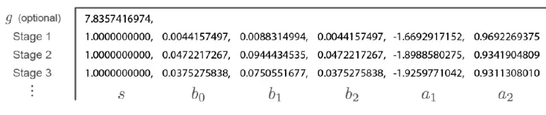
Each coefficient must be in the range [-4.0,+4.0). Internally, these are represented as signed 48-bit fixed-point numbers, with 45 fractional bits. The output scaling can be up to 8,000,000. Filter coefficients can be computed using signal processing toolboxes in e.g. MATLAB or SciPy. Some coefficients may result in overflow or underflow, which degrade filter performance. Check filter responses prior to use.
Output switches
Connect or disconnect the output signal using switches. When a switch is in the open state, the output signal will be the output offset voltage.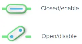
Probe points
The Moku:Go Digital Filter Box has an integrated oscilloscope that can be used to probe the signal at the input, pre-filter, and output stages. Add the probe points by clicking the![]() icon.
icon.
Oscilloscope
| ID | Parameter | Description |
| 1 | Input probe point | Click to place the probe point at the input. |
| 2 | Pre-filter probe point | Click to place the probe after the input gain. |
| 3 | Output probe point | Click to place the probe at the output. |
| 4 | Oscilloscope/Data Logger toggle | Toggle between the built-in Oscilloscope or Data Logger. |
| 5 | Measurement* | Measurement function for the built-in oscilloscope. |
| 6 | Oscilloscope* | Signal display area for the oscilloscope. |
Detailed instructions for the oscilloscope instrument can be found in the Moku:Go Oscilloscope manual.
Data Logger
| ID | Parameter | Description |
| 1 | Input probe point | Click to place the probe point at the input. |
| 2 | Pre-Filter probe point | Click to place the probe before the filter. |
| 3 | Output probe point | Click to place the probe at the output. |
| 4 | Oscilloscope/Data Logger toggle | Toggle between the built-in Oscilloscope or Data Logger. |
| 5 | Data Logger | Refer to the Moku:Go Data Logger manual for the details. |
The Embedded Data Logger can stream over a network or save data on the Moku. For details, refer to the Data Logger user manual. More streaming information is in our API documents at apis.liquidinstruments.com.
Additional tools
The Moku:
Go app has two built-in file management tools: File Manager and File Converter. The File Manager allows users to download the saved data from Moku:Go to a local computer, with optional file format conversion. The file converter converts the Moku:Go binary (.li) format on the local computer to either .csv, .mat, or .npy format.
File Manager
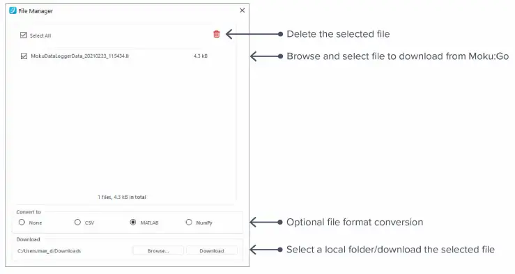
Once a file is transferred to the local computer, a![]() icon shows up next to the file.
icon shows up next to the file.
File Converter
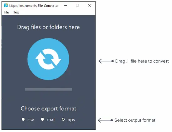
The converted file is saved in the same folder as the original file.
Liquid Instruments File Converter has the following menu options:
| Options | Shortcut | Description |
| File | ||
| · Open file | Ctrl+O | Select a .li file to convert |
| · Open folder | Ctrl+Shift+O | Select a folder to convert |
| · Exit | Close the file converter window | |
| Help | ||
| · Liquid Instruments website | Access Liquid Instruments website | |
| · Report an issue | Report bug to Liquid Instruments | |
| · About | Show app version, check update, or license information |
Power Supply
The Moku:Go Power Supply is available on M1 and M2 models. M1 features a 2-channel Power Supply, while M2 features a 4-channel Power Supply. Access the Power Supply control window in all instruments under the main menu.
The Power Supply operates in two modes: constant voltage (CV) or constant current (CC) mode. For each channel, the user can set a current and voltage limit for the output. Once a load is connected, the Power Supply operates either at the set current or set voltage, whichever comes first. If the Power Supply is voltage limited, it operates in the CV mode. If the Power Supply is current limited, it operates in the CC mode.
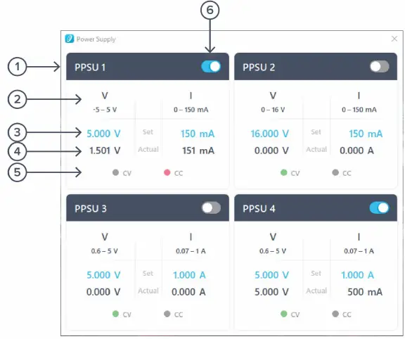
| ID | Function | Description |
| 1 | Channel name | Identifies the Power Supply being controlled |
| 2 | Channel range | Indicates the voltage/current range of the channel |
| 3 | Set value | Click the blue numbers to set the voltage and current limit |
| 4 | Readback numbers | Voltage and current readback from the Power Supply, the actual voltage and current being supplied to the external load |
| 5 | Mode indicator | Indicates if the Power Supply is in CV (green) or CC (red) mode |
| 6 | On/Off toggle | Click to turn the Power Supply on and off |
Ensure Moku:Go is fully updated. For the latest information, visit: liquidinstruments.com.
Moku:Go Digital Filter Box User Manual
© 2023 Liquid Instruments. All rights reserved.


