Liquid instruments Moku Logic Analyzer /Patter Generator Liquid
User Interface 
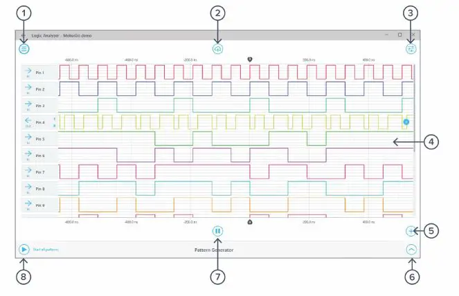
- Main menu
- Add channel
- Save data
- Output pattern editor
- Settings
- Input start/pause
- Signal display area
- Start pattern generation
Physical Interface
Moku:Go is equipped with a 20-pin digital I/O interface. 16 of the 20 pins are the bidirectional digital I/O. There are two ground pins, one 5 V, and one 3.3 V output. A detailed layout can be found in the following figure.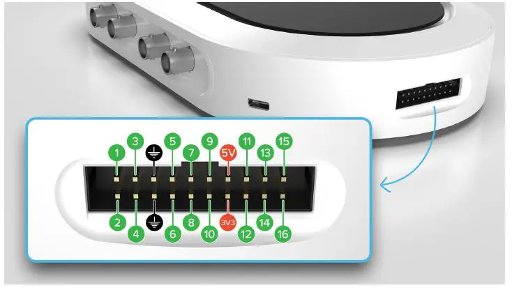
The main menu can be accessed by clicking the icon on the top-left corner. 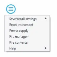
This menu provides the following options:
| Options | Shortcuts | Description |
| Save/recall settings: | ||
| · Save instrument state | Ctrl+S | Save the current instrument settings. |
| · Load instrument state | Ctrl+O | Load last saved instrument settings. |
| · Show current sate | Show the current instrument settings. | |
| Reset instrument | Ctrl+R | Reset the instrument to its default state. |
| Power supply | Access power supply control window.* | |
| File manager | Open file manager tool.** | |
| File converter | Open file converter tool.** | |
| Help | ||
| · Liquid Instruments website | Access Liquid Instruments website. | |
| · Shortcuts list | Ctrl+H | Show Moku:Go app shortcuts list. |
| · Manual | F1 | Access instrument manual. |
| · Report an issue | Report bug to Liquid Instruments. | |
| · About | Show app version, check update, or license information. |
- Power supply is available on Moku:Go M1 and M2 models. Detailed information about power supply can be found in Moku:Go power supply manual.
- Detailed information about the file manager and file converter can be found at the end of this user manual.
Export data
The export data options can be accessed by pressing the icon, allowing you to: 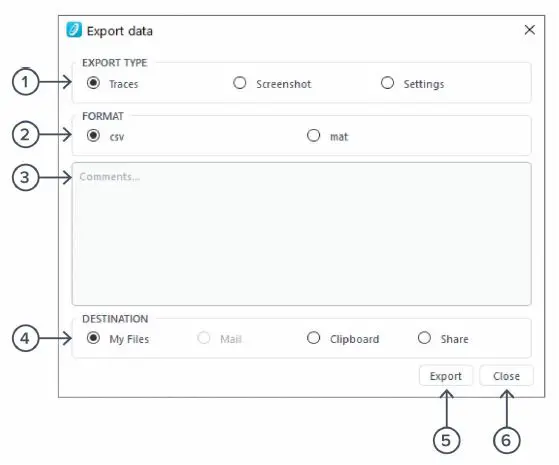
- Select the type of data to export.
- Select the exporting format (CSV or MAT).
- Enter additional comments for the saved file.
- Select the exporting location on your local computer.
- Click to export data.
- Click to close the export data window
Signal display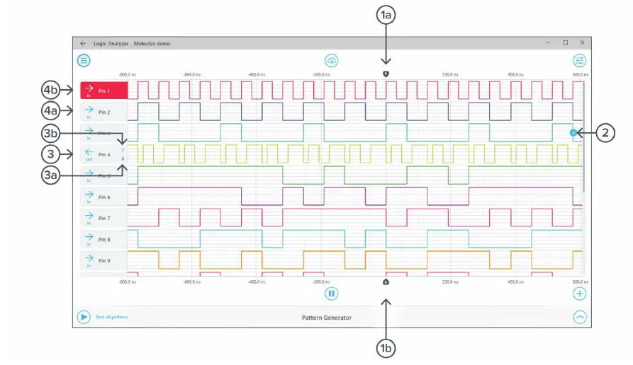
| ID | Button | Description |
| 1a | Top time origin mark | Marks the “zero second” point on the time scale. This will be the trigger point if the logic analyzer has triggered. |
| 1b | Bottom time origin mark | Marks the “zero second” point on the time scale. This will be the trigger point if the logic analyzer has triggered. |
| 2 | Remove trace | Click here to remove the trace. It will appear when the mouse cursor is over the signal trace area for this pin on the signal display. |
| 3 | Output pin header | Signal header for Pin 4. The left pointing arrow indicates it is currently set to be an output channel. Click the arrow to switch direction. |
| 3a | Low override | Click to override this output to Low. |
| 3b | High override | Click to override this output to High. |
| 4a | Input pin header | Signal header for Pin 3. The right pointing arrow indicates it is currently set to be an input channel. Click the arrow to switch direction. |
| 4b | Active pin header | Click the signal trace area or pin header for any pin to make it the active signal. This allows user to access settings and pattern editor for this pin. Click the header again to deselect the active pin. |
Signal display navigation
The displayed signal can be moved around the screen by clicking anywhere on the signal display window and dragging to the new position.
Scrolling the mouse wheel zooms in and out along the time axis.
Add channel
| Options | Shortcuts | Description |
| Add pin | Select a specific pin to add. | |
| Add next available pin | Ctrl+N | Add the next pin that is not currently in use. |
| Add math channel | Ctrl+M | Add a math channel. |
Settings
The settings options can be accessed by clicking the icon, allowing you to reveal or hide the controls drawer, giving you access to all instrument settings. The controls drawer contains settings, and measurement.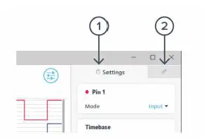
| ID | Description |
| 1 | Settings |
| 2 | Measurements |
Settings
The settings pane allows you to configure the active pin, timebase, and trigger settings.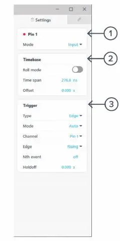
| ID | Button | Description |
| 1 | Active pin settings | Different options are available for input, output pins, and math channels. |
| 2 | Timebase | Roll mode: Toggle between roll and sweep mode. Timespan: Horizontal screen scale. Changes dynamically when zooms in and out a trace or can be entered manually. Offset: Horizontal trigger point offset. Changes dynamically when horizontally dragging a trace or can be set manually. |
| 3 | Trigger | Type: Select between edge and pulse triggering. Mode: Switches between auto, normal and single trigger modes. Channel: Select the source for the trigger circuit. Edge: Select to trigger on rising, falling, or both edge. It is only available for edge trigger. Polarity and Width: Select the trigger polarity and width condition. It is only available for pulse trigger. Nth event : Select up to 65,535 trigger events before actually triggering. HoldOff : Select a time to holdoff trigger post trigger event |
| Options | Description |
| Mode | Select between input and output mode. |
| Options | Description |
| Mode | Select between input and output mode. |
| Output override | Select to override the output with ‘Low’ or ‘High’ |
| Options | Description |
| Source A | Select the first source for the math operation. |
| Operation | Select from AND, OR, XOR, NAND, NOR, XNOR operation. |
| Source B | Select the second source for the math operation. |
Measurement
The measurement pane allows you to add/remove measurements. A measurement can be assigned to a specific input, output, math channel, or difference between any two channels.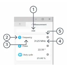
| ID | Description |
| 1 | Click to add additional measurement tile. |
| 2 | Measurement source. Click to loop through the measurement sources. |
| 3 | Measurement type. |
| 4 | Measurement value. |
| 5 | Click to remove the measurement tile. |
Click a measurement tile to open the menu to adjust the measurement. The following options are available:
| Options | Description |
| Type | Select the measurement type. |
| · Frequency | |
| · Phase | |
| · Period | |
| · Duty cycle | |
| · Pulse width | |
| · Neg width | |
| Channels | Select measurement source. |
| Difference Channels | Measure the difference between the measurement source to another channel. |
| Remove | Remove the measurement tile. |
Pattern Editor
The output pattern can be accessed by clicking the icon. The editor only acts on the selected active output channel. There are in total four output modes: clock, pulse, random, and custom.
Clock mode 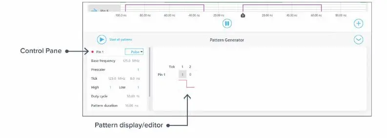
In the clock mode, the user can view (gray numbers) and adjust (blue numbers) the following parameters under the control pane:
| Parameter | Description |
| Base frequency | The base frequency of the Go, which is the fastest operational frequency. |
| Prescaler | Divider to scale down the base frequency to the tick frequency. For example, a prescaler number of 2 provides 62.5 MHz tick frequency. |
| Pattern duration | Total duration of the pattern (1 cycle), calculated based on the current user settings. |
| Repeat forever | Change between repeat mode or n-iteration mode. |
| Loop rate | In the repeat mode, it displays the loop rate based on the current user settings. |
| Iterations | In the n-iteration mode, set the number of pattern iterations to output. |
Pulse mode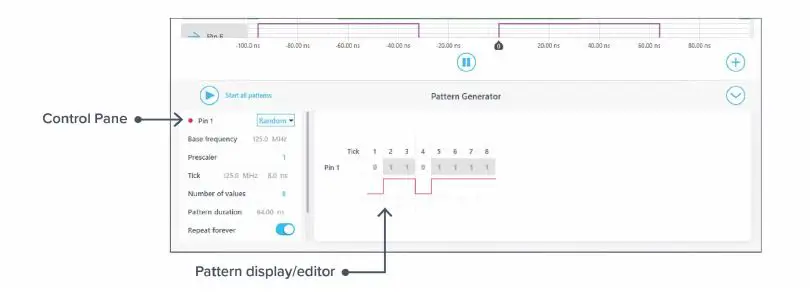
With the pulse mode, the user can output a pattern with a set number of high and low ticks. A few additional parameters are available in the pulse mode:
| Parameter | Description |
| High | Number of ticks for high. |
| Low | Number of ticks for low. |
| Duty cycle | Percentage of the pattern that is high during the pulse pattern. |
Random mode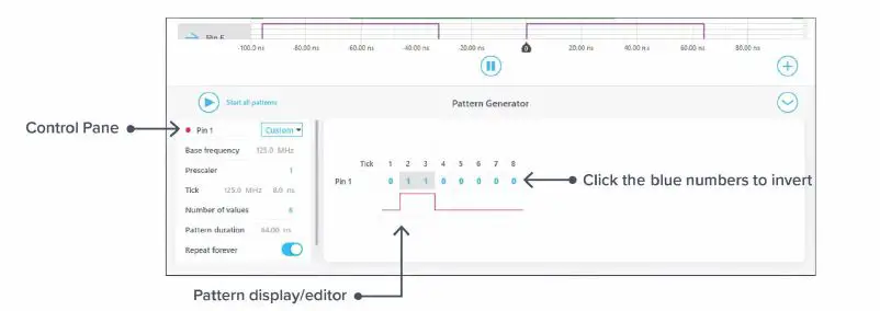
In the random mode, the user can generate a random pattern with a set number of ticks. A few additional parameters are avaiable in the pulse mode:
| Parameter | Description |
| Number of values | A total number of ticks for the random pattern. |
| New random seed | Generate new random pattern. |
Custom mode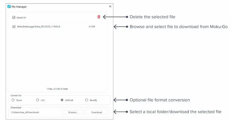
In the custom mode, the user can design a pattern with the pattern designer. You can click the blue number in the pattern display/editor area to invert the polarity for the tick.
Additional Tools
Moku: Go app has two built-in file management tools: file manager and file converter.
File Manager
The file manager allows the user to download the saved data from Moku:Go to the local computer, with optional file format conversion.
Once a file is transferred to the local computer, a icon shows up next to the file.
File Converter
The file converter converts the Moku:Go’s binary (.li) format on the local computer to either .csv, .mat, or .npy format.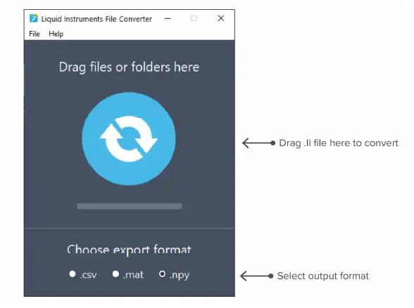
The converted file is saved in the same folder as the original file. Liquid Instruments File Converter has the following menu options:
| Options | Shortcut | Description |
| File | ||
| · Open file | Ctrl+O | Select a .li file to convert |
| · Open folder | Ctrl+Shift+O | Select a folder to convert |
| · Exit | Close the file converter window | |
| Help | ||
| · Liquid Instruments website | Access Liquid Instruments website | |
| · Report an issue | Report bug to Liquid Instruments | |
| · About | Show app version, check update, or license information |
Power Supply
Moku:Go Power supply is available on M1 and M2 models. M1 features a 2-channel power supply, while M2 features a 4-channel power supply. The power supply control window can be accessed in all instruments under the main menu. The power supply operates in two modes: constant voltage (CV) or constant current (CC) mode. For each channel, the user can set a current and voltage limit for the output. Once a load is connected, the power supply operates either at the set current or set voltage, whichever comes first. If the power supply is voltage limited, it operates in the CV mode. If the power supply is current limited, it operates in the CC mode.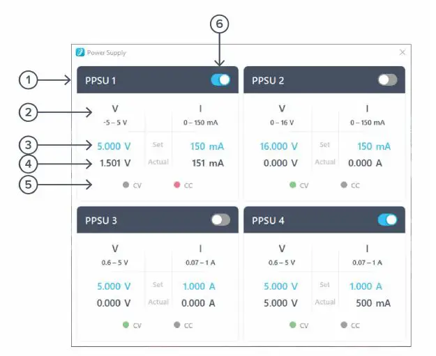
| ID | Function | Description |
| 1 | Channel name | Identifies the power supply being controlled. |
| 2 | Channel range | Indicates the voltage/current range of the channel. |
| 3 | Set value | Click the blue numbers to set the voltage and current limit. |
| 4 | Readback numbers | Voltage and current readback from the power supply, the actual voltage and current being supplied to the external load. |
| 5 | Mode indicator | Indicates if the power supply is in CV (green) or CC (red) mode. |
| 6 | On/Off Toggle | Click to turn the power supply on and off. |


