Liquid Instruments Moku:Pro PID Controller Flexible High Performance Software
PID Controller Moku
Pro User Manual
The Moku: Pro PID (Proportional-Integrator-Differentiator)
Controller is a device that features four fully real-time configurable PID controllers with a closed-loop bandwidth of >100 kHz. This enables them to be used in applications requiring both low and high feedback bandwidths such as temperature and laser frequency stabilization. The PID Controller can also be used as a lead-lag compensator by saturating the integral and differential controllers with independent gain settings.
Product Usage Instructions
To use the Moku:Pro PID Controller, follow the steps below:
- Ensure that the Moku:Pro device is fully updated. For the latest information, visit www.liquidinstruments.com.
- Access the main menu by pressing the icon on the user interface.
- Configure the input settings for Channel 1 and Channel 2 by accessing the input configuration options (2a and 2b).
- Configure the control matrix (option 3) to set up the MIMO controllers for PID 1 / 2 and PID 3 / 4.
- Configure the PID Controller settings for PID Controller 1 and PID Controller 2 (options 4a and 4b).
- Enable the output switches for Channel 1 and Channel 2 (options 5a and 5b).
- Enable the integrated Data Logger (option 6) and/or the integrated Oscilloscope (option 7) as needed.
Note that throughout the manual, default colors are used to present instrument features, but you can customize the color representations for each channel in the preferences pane accessed via the main menu.
The Moku:Pro PID (Proportional-Integrator-Differentiator) Controller features four fully real-time configurable PID controllers with a closed-loop bandwidth of >100 kHz. This enables them to be used in applications requiring both low and high feedback bandwidths such as temperature and laser frequency stabilization. The PID Controller can also be used as a lead-lag compensator by saturating the integral and differential controllers with independent gain settings.
Ensure Moku:Pro is fully updated. For the latest information:
User Interface
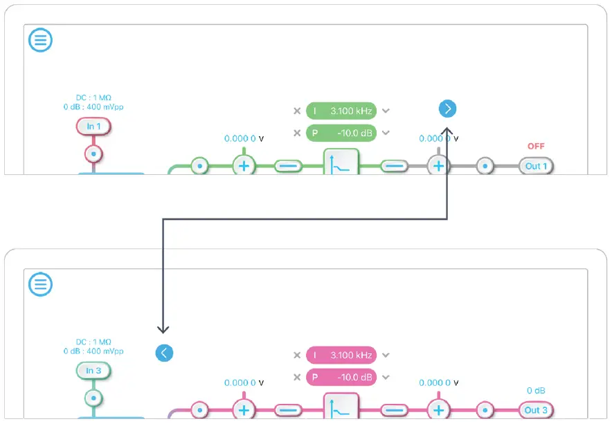
Moku: Pro is equipped with four inputs, four outputs, and four PID controllers. Two control matrices are used to create two multiple-input and multiple-output (MIMO) controllers for PID 1 / 2, and PID 3/ 4. You can tap the ![]() or
or![]() icons to switch between MIMO group 1 and 2. MIMO group 1 (inputs 1 and 2, PID 1 and 2, Output 1 and 2) is used throughout this manual. The settings for MIMO group 2 are similar to MIMO group 1.
icons to switch between MIMO group 1 and 2. MIMO group 1 (inputs 1 and 2, PID 1 and 2, Output 1 and 2) is used throughout this manual. The settings for MIMO group 2 are similar to MIMO group 1.
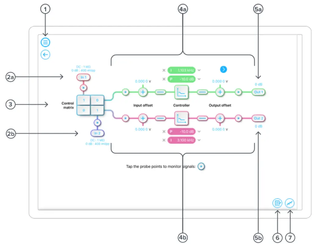
| ID | Description |
| 1 | Main menu. |
| 2a | Input configuration for Channel 1. |
| 2b | Input configuration for Channel 2. |
| 3 | Control matrix. |
| 4a | Configuration for PID Controller 1. |
| 4b | Configuration for PID Controller 2. |
| 5a | Output switch for Channel 1. |
| 5b | Output switch for Channel 2. |
| 6 | Enable the integrated Data Logger. |
| 7 | Enable the integrated Oscilloscope. |
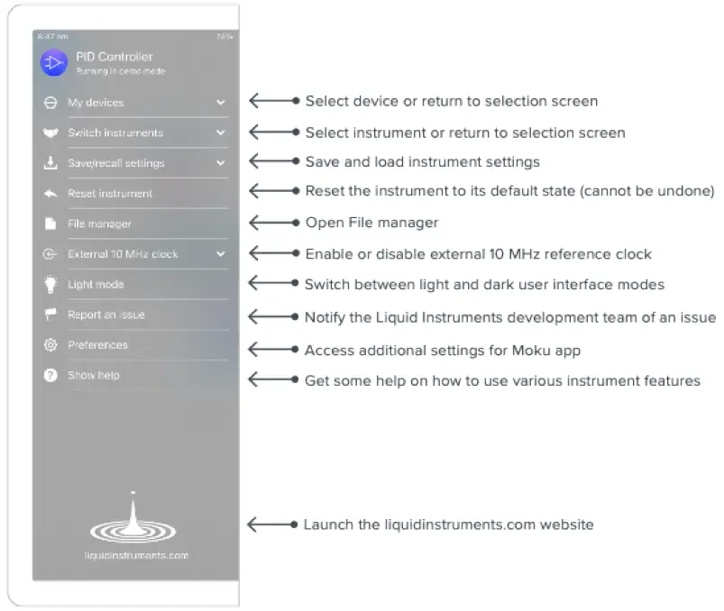
The main menu can be accessed by pressing the![]() icon, allowing you to:
icon, allowing you to:
Preferences
The preferences pane can be accessed via the main menu. In here, you can reassign the color representations for each channel, connect to Dropbox, etc. Throughout the manual, the default colors (shown in the figure below) are used to present instrument features.
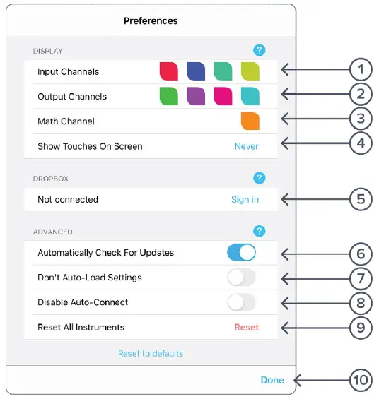
| ID | Description |
| 1 | Tap to change the color associated with input channels. |
| 2 | Tap to change the color associated with output channels. |
| 3 | Tap to change the color associated with math channel. |
| 4 | Indicate touch points on the screen with circles. This can be useful for demonstrations. |
| 5 | Change the currently linked Dropbox account to which data can be uploaded. |
| 6 | Notify when a new version of the app is available. |
| 7 | Moku:Pro automatically saves instrument settings when exiting the app, and restores them again at launch. When disabled, all settings will be reset to defaults on launch. |
| 8 | Moku:Pro can remember the last used instrument and automatically reconnect to it at launch. When disabled, you will need to manually connect every time. |
| 9 | Reset all instruments to their default state. |
| 10 | Save and apply settings. |
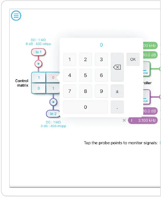
Input Configuration
The input configuration can be accessed by tapping the![]() or
or![]() icon, allowing you to adjust the coupling, impedance and input range for each input channel.
icon, allowing you to adjust the coupling, impedance and input range for each input channel.
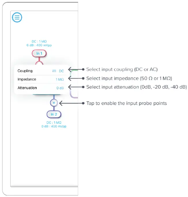
Details about the probe points can be found in the Probe Points section.
Control Matrix
The control matrix combines, rescales, and redistributes the input signal to the two independent PID controllers. The output vector is the product of the control matrix multiplied by the input vector.
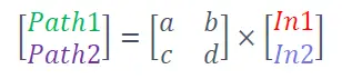
where
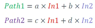
For example, a control matrix of ![]() equally combines the Input 1 and Input 2 to the top Path1 (PID Controller 1); multiples Input 2 by a factor of two, and then sends it to the bottom Path2 (PID Controller 2).
equally combines the Input 1 and Input 2 to the top Path1 (PID Controller 1); multiples Input 2 by a factor of two, and then sends it to the bottom Path2 (PID Controller 2).
The value of each element in the control matrix can be set between -20 to +20 with 0.1 increments when the absolute value is less than 10, or 1 increment when the absolute value is between 10 and 20. Tap the element to adjust the value.
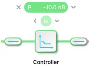
PID Controller
The four independent, fully real-time configurable PID controllers are grouped into two MIMO groups. MIMO group 1 is shown here. In MIMO group 1, PID controller 1 and 2 follow the control matrix in the block diagram, represented in green and purple, respectively. The settings for all controller paths are the same.
User Interface
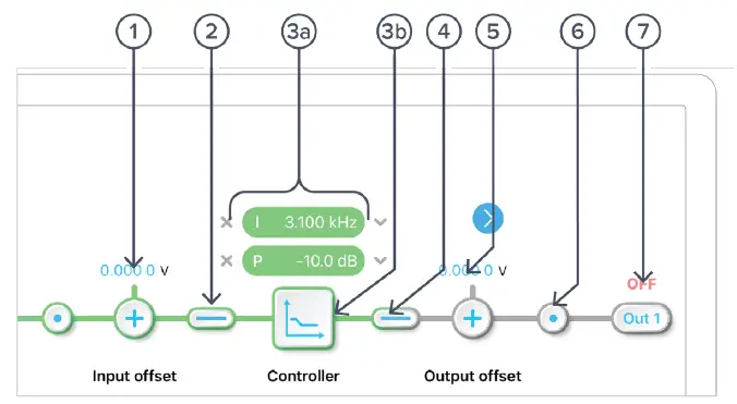
| ID | Parameter | Description |
| 1 | Input offset | Tap to adjust the input offset (-1 to +1 V). |
| 2 | Input switch | Tap to zero the input signal. |
| 3a | Quick PID control | Tap to enable/disable controllers and adjust the parameters. Not available in advanced mode. |
| 3b | Controller view | Tap to open full controller view. |
| 4 | Output switch | Tap to zero the output signal. |
| 5 | Output offset | Tap to adjust the output offset (-1 to +1 V). |
| 6 | Output probe | Tap to enable/disable the output probe point. See Probe Points section for details. |
| 7 | Moku:Pro output switch | Tap to disable or enable DAC output with 0 dB or 14 dB gain. |
Input / Output Switches
 Closed/Enable
Open/disable
Controller (Basic Mode)
Controller Interface
Tap the![]() icon to open the full controller view.
icon to open the full controller view.
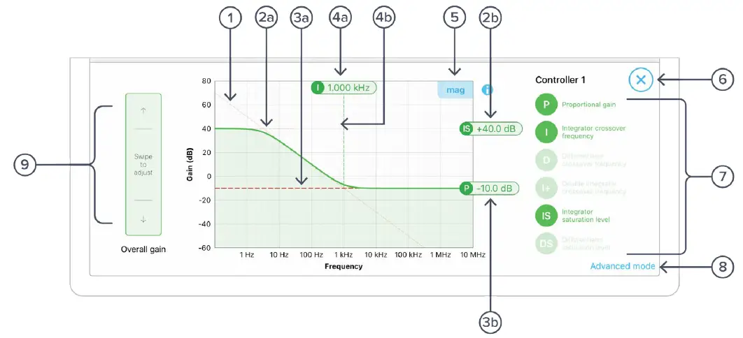
| ID | Parameter | Description |
| 1 | Design cursor 1 | Cursor for Integrator (I) setting. |
| 2a | Design cursor 2 | Cursor for Integrator Saturation (IS) level. |
| 2b | Cursor 2 reading | Reading for IS level. Drag to adjust the gain. |
| 3a | Design cursor 3 | Cursor for Proportional (P) gain. |
| 3b | Cursor 3 reading | Reading of the P gain. |
| 4a | Cursor 4 reading | Reading for I crossover frequency. Drag to adjust the gain. |
| 4b | Design cursor 4 | Cursor for I crossover frequency. |
| 5 | Display toggle | Toggle between magnitude and phase response curve. |
| 6 | Close controller view | Tap to close the full controller view. |
| 7 | PID control switches | Turn on/off individual controller. |
| 8 | Advanced mode | Tap to switch to the advanced mode. |
| 9 | Overall gain slider | Swipe to adjust overall gain of the controller. |
PID Response Plot
The PID response plot provides an interactive representation (gain as a function of frequency) of the controller.
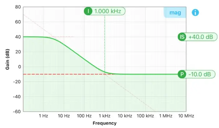
The green/purple solid curve represents the active response curve for PID Controller 1 and 2, respectively.
The green/purple dashed vertical lines (4) represent the cursors crossover frequencies, and/or unity gain frequencies for PID Controller 1 and 2, respectively.
The red dashed lines (○1 and 2) represent the cursors for each controller.
The bold red dashed line (3) represents the cursor for actively selected parameter.
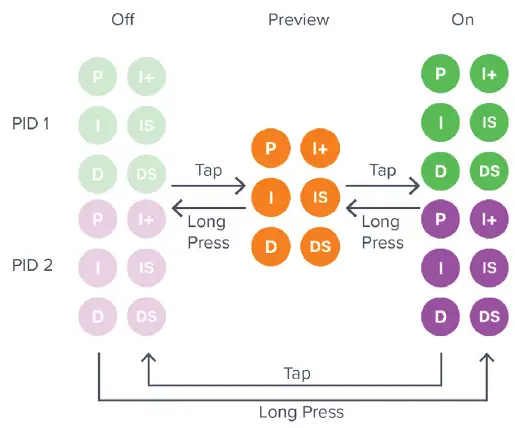
PID Paths
There are six switch buttons for the controller:
| ID | Description | ID | Description |
| P | Proportional gain | I+ | Double integrator crossover frequency |
| I | Integrator crossover frequency | IS | Integrator saturation level |
| D | Differentiator | DS | Differentiator saturation level |
Each button has three states: off, preview, and on. Tap or click the buttons to rotate through these states. Long press the buttons to go reverse order.
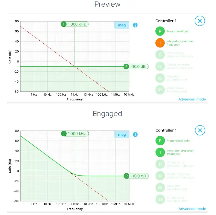
PID Path Preview
PID path preview allows the user to preview and adjust the settings on the PID response plot before engaging.
List of Configurable Parameters in Basic Mode
| Parameters | Range |
| Overall gain | ± 60 dB |
| Proportional gain | ± 60 dB |
| Integrator crossover frequency | 312.5 mHz to 3.125 MHz |
| Double integrator crossover | 3,125 Hz to 31.25 MHz |
| Differentiator crossover frequency | 3.125 Hz to 31.25 MHz |
| Integrator saturation level | ± 60 dB or limited by the crossover frequency/proportional gain |
| Differentiator saturation level | ± 60 dB or limited by the crossover frequency/proportional gain |
Controller (Advanced Mode)
In Advanced Mode, users can build fully customized controllers with two independent sections (A and B), and six adjustable parameters in each section. Tap the Advanced Mode button in the full controller view to switch to the Advanced Mode.
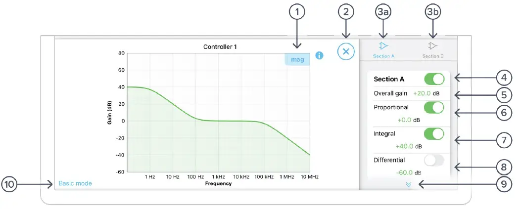
| ID | Parameter | Description |
| 1 | Display toggle | Toggle between magnitude and phase response curve. |
| 2 | Close controller view | Tap to close the full controller view. |
| 3a | Section A pane | Tap to select and configure Section A. |
| 3b | Section B pane | Tap to select and configure Section B. |
| 4 | Section A Switch | Master switch for Section A. |
| 5 | Overall gain | Tap to adjust the overall gain. |
| 6 | Proportional panel | Tap the switch to enable/disable proportional path. Tap the number to adjust the gain. |
| 7 | Integrator panel | Tap the switch to enable/disable integrator path. Tap the number to adjust the gain. |
| 8 | Differentiator panel | Tap the switch to enable/disable differential path. Tap the number to adjust the gain. |
| 9 | Additional Settings | |
| Integrator corner frequency | Tap to set the frequency of the integrator corner. | |
| Differentiator corner frequency | Tap to set the frequency of the differentiator corner. | |
| 10 | Basic mode | Tap to switch to the basic mode. |
Quick PID Control
This panel allows user quickly to view, enable, disable, and adjust the PID controller without open the controller interface. It is only available in basic PID mode.
Tap the![]() icon to disable active controller path.
icon to disable active controller path.
Tap the![]() icon to select the controller to adjust.
icon to select the controller to adjust.
Tap the faded icon (i.e.![]() ) to enable the path.
) to enable the path.
Tap the active controller path icon (i.e.![]() ) to enter the value. Hold and slide to adjust the value.
) to enter the value. Hold and slide to adjust the value.
Probe Points
The Moku:Pro PID controller has an integrated oscilloscope and data logger that can be used to probe the signal at the input, pre-PID, and output stages. The probe points can be added by tapping the![]() icon.
icon.
Oscilloscope
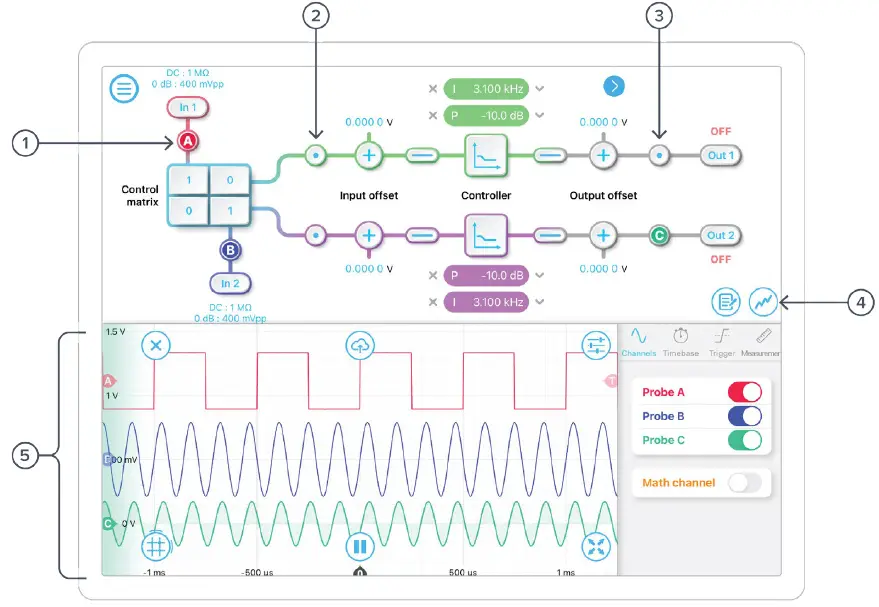
| ID | Parameter | Description |
| 1 | Input probe point | Tap to place the probe point at input. |
| 2 | Pre-PID probe point | Tap to place the probe after the control matrix. |
| 3 | Output probe point | Tap to place the probe at output. |
| 4 | Oscilloscope/data logger toggle | Toggle between built-in oscilloscope or data logger. |
| 5 | Oscilloscope | Refer to the Moku:Pro Oscilloscope manual for the details. |
Data Logger
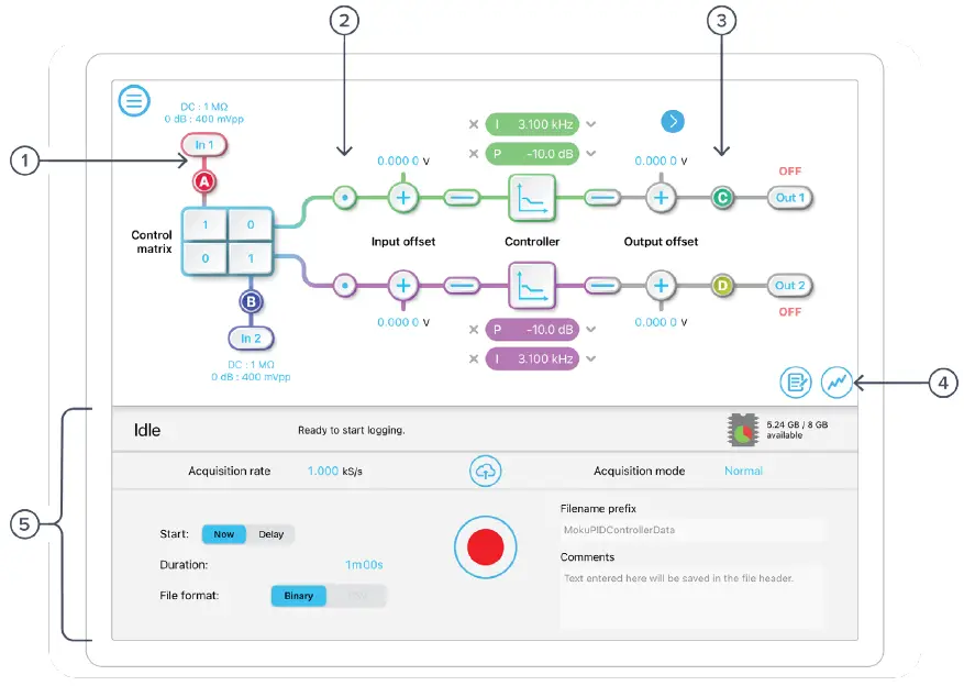
| ID | Parameter | Description |
| 1 | Input probe point | Tap to place the probe point at input. |
| 2 | Pre-PID probe point | Tap to place the probe after the control matrix. |
| 3 | Output probe point | Tap to place the probe at output. |
| 4 | Oscilloscope/Data Logger toggle | Toggle between built-in Oscilloscope or Data Logger. |
| 5 | Data Logger | Refer to the Moku:Pro Data Logger manual for the details. |
The Embedded Data Logger can stream over a network or save data on the Moku. For details, refer to the Data Logger user manual. More streaming information is in our API documents at apis.liquidinstruments.com
Ensure Moku:Pro is fully updated. For the latest information:
© 2023 Liquid Instruments. All rights reserved.


