![]()
![]() 48×48 Self Tune PID Process
48×48 Self Tune PID Process
Controller with Ramp / Soak Profile
Operation Manual
epsilon_48x48 Self Tune PID Process Controller with Ramp / Soak Profile
![]() This brief manual is primarily meant for quick reference to wiring connections and parameter searching. For more details on operation and application; please log on to www.ppiindia.net
This brief manual is primarily meant for quick reference to wiring connections and parameter searching. For more details on operation and application; please log on to www.ppiindia.net
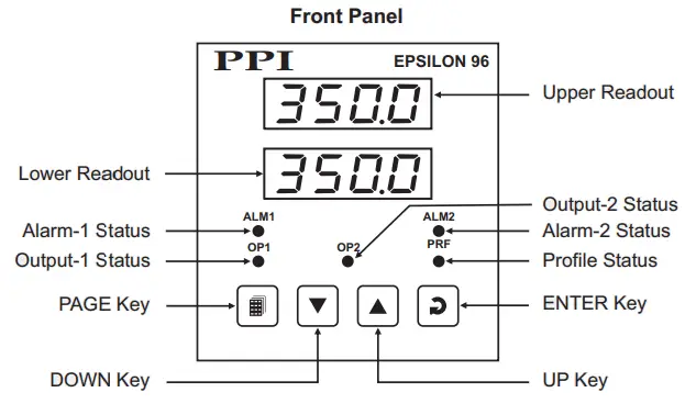
FRONT PANEL LAYOUT
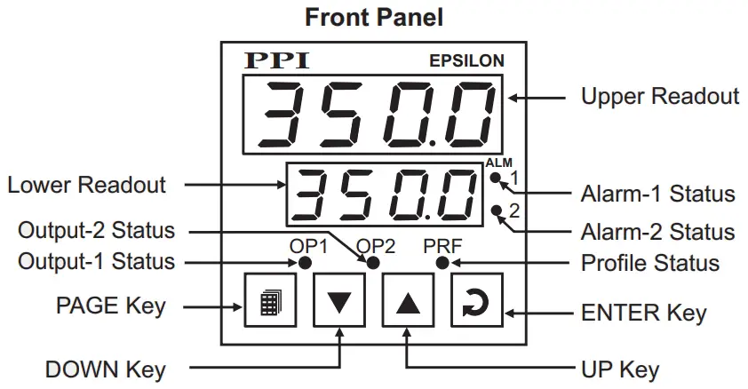
Keys Operation
| Symbol | Key | Function |
 | PAGE | Press to enter or exit set-up mode. |
 | DOWN | Press to decrease the parameter value. Pressing once decreases the value by one count; keeping pressed speeds up the change. |
 | UP | Press to increase the parameter value. Pressing once increases the value by one count; holding pressed speeds up the change. |
 | ENTER | Press to store the set parameter value and to scroll to the next parameter on the PAGE. |
PV Error Indications
| Message | PV Error Type |
 | Over-range (PV above Max. Range) |
 | Under-range (PV below Min. Range) |
 | Open (Sensor open / broken) |
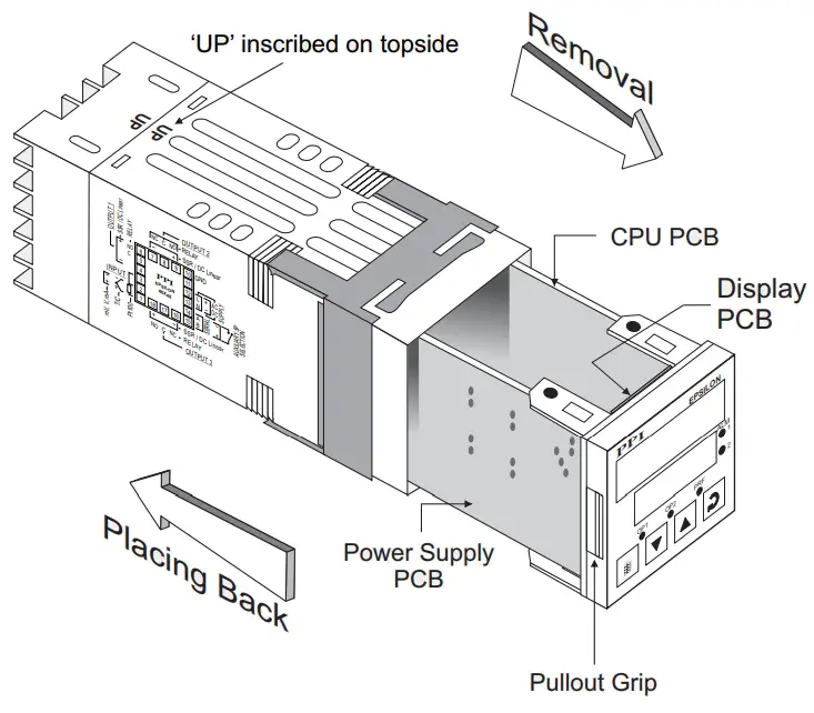
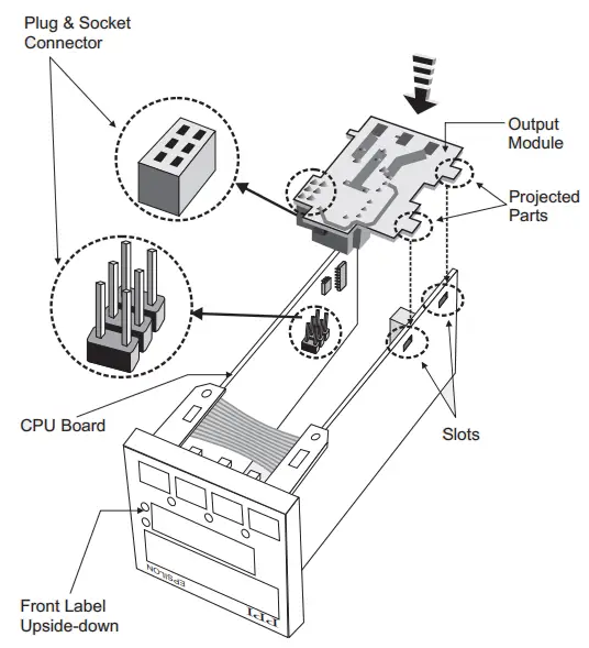
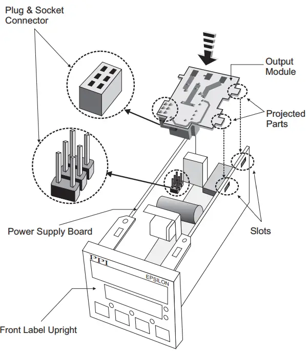
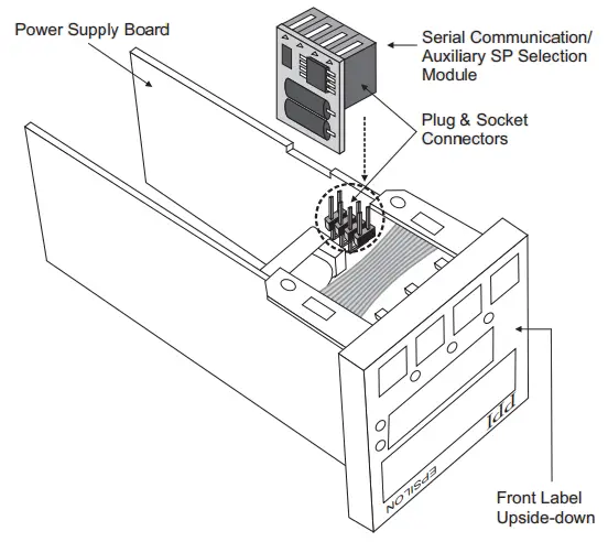
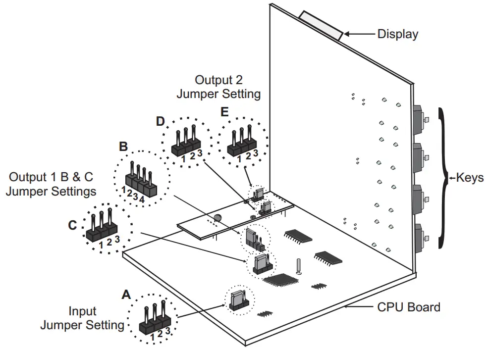
ENCLOSURE ASSEMBLY
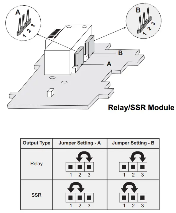
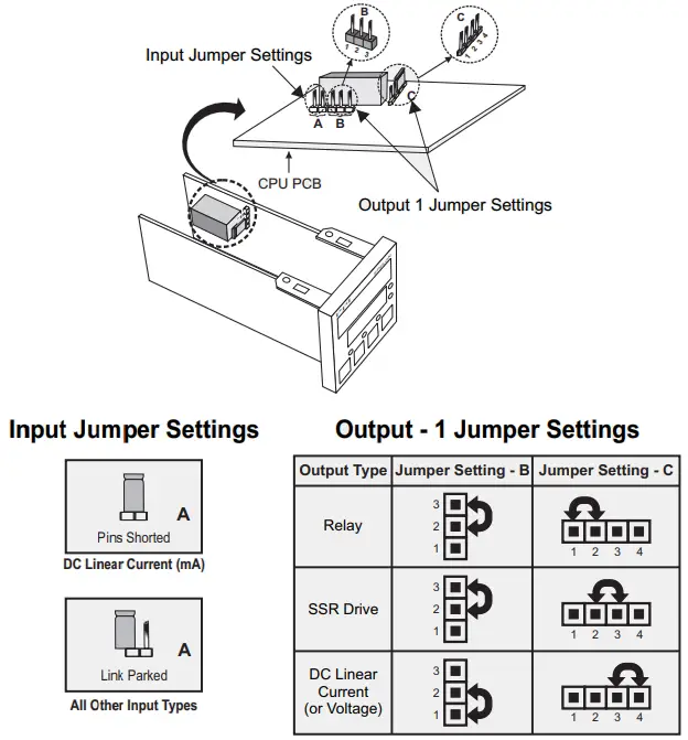
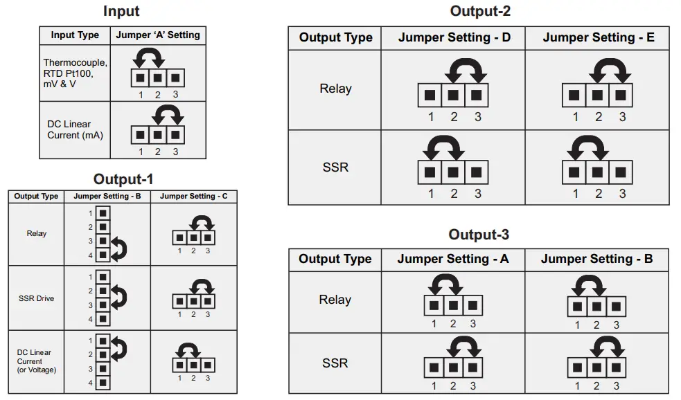
JUMPER SETTINGS
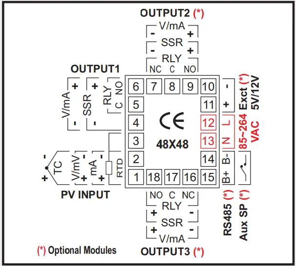
OUTPUT-2 & OUTPUT-3
MOUNTING DETAILS
OUTPUT-3 MODULE
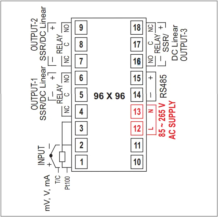
ELECTRICAL CONNECTIONS
JUMPER SETTINGS
INPUT & OUTPUT-1
MOUNTING DETAILS
OUTPUT-2 MODULE
SERIAL COMM. MODULE
CONFIGURATION PARAMETERS
| Parameters | Settings (Default Value) |
| Control Output (OP1) Type | (Default : Relay) |
| Control Action | (Default : PID) |
| Control Logic | (Default : Reverse) |
| Input Type | Refer Table 1 (Default : Type K) |
| PV Resolution | Refer Table 1 (Default : 1) |
| PV Units | (Default : C)° |
| PV Range Low PV Range High | -1999 to 9999 (Default : 0) -1999 to 9999 (Default : 1000) |
| Setpoint Low Limit | Min. Range for the (Default : -199) selected Input Type to Setpoint High Limit |
| Setpoint High Limit | Setpoint Low Limit to Max. Range for the selected Input Type (Default : 1376) |
| Offset for PV | -199 to 999 or -199.9 to 999.9 (Default : 0) |
| Digital Filter Time Constant | 0.5 to 60.0 Seconds (in steps of 0.5 Seconds) (Default : 2.0 Sec.) |
| Sensor Break Output Power | -100 to 100 (Default : 0) |
CONTROL PARAMETERS
| Parameters | Settings (Default Value) |
| Proportional Band | 1 to 999 Units (Default : 50 units) |
| Integral Time | 0 to 3600 Seconds (Default : 100 Sec.) |
| Derivative Time | 0 to 600 Seconds (Default : 16 Sec.) |
| Cycle Time | 0.5 to 100.0 Seconds (in steps of 0.5 secs.) (Default : 10.0 Sec.) |
| Relative Cool Gain | 0.1 to 10.0 (Default : 1.0) |
| Cool Cycle Time | 0.5 to 100.0 Seconds (in steps of 0.5 secs.) (Default : 10.0 Sec.) |
| Hysteresis | 1 to 999 (Default : 2) |
| Pulse Time | Pulse ON Time to 120.0 Seconds (Default : 2.0 sec.) |
| ON Time | 0.1 to Value set for Pulse Time (Default : 1.0) |
| Cool Hysteresis | 1 to 999 (Default : 2) |
| Cool Pulse Time | Cool ON Time to 120.0 Seconds (Default : 2.0) |
| Cool ON Time | 0.1 to Value set for Cool Pulse Time (Default : 1.0) |
| Heat Power Low | 0 to Power High (Default : 0) |
| Heat Power High | Power Low to 100 (Default : 100) |
| Cool Power Low | 0 to Cool Power High (Default : 0) |
| Cool Power High | Cool Power Low to 100 (Default : 100) |
Controller supplied with Bi-Directional control (Heat + Cool) mode option.
SUPERVISORY PARAMETERS
| Parameters | Settings (Default Value) |
| Self-Tune Command | (Default : No) |
| Overshoot Inhibit | (Default : Disable) |
| Overshoot Inhibit Factor | 1.0 to 2.0 (Default : 1.0) |
| SP Adjustment on Lower Readout | (Default : Enable) |
| SP Adjustment on Operator Page | (Default : Enable) |
| Alarm SP Adjustment on Operator Page | (Default : Disable) |
| Standby Mode | (Default : Disable) |
| Profile Abort Command on Operator Page | (Default : Disable) |
| Utility Option Selection | (Default : Serial Comm. |
| Baud Rate | 4800 9600 19200 38400 57600 (Default : 9.6) |
| Communication Parity |  (Default : Even) |
| Controller ID Number | 1 to 127 (Default : 1) |
| Communication Write Enable |  (Default : No) |
OP2 & OP3 FUNCTION PARAMETERS
| Parameters | Settings (Default Value) |
| Output-2 Function Selection | 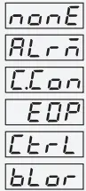 None NoneAlarm Cool Control End Of Profile Auxiliary Control Blower (Default : None) |
| Alarm-1 Logic |  Normal NormalReverse (Default : Normal) |
| Output-2 Type | 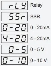 (Default : Relay) |
| OP2 Event Status | 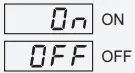 (Default : ON) |
| OP2 Event Time | 0 to 9999 (Default : 0) |
| OP2 Event Time Units | 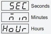 (Default : Seconds) |
| Offset Value for Auxiliary Control Setpoint | -199 to 999 or -199.9 to 999.9 (Default : 0) |
| Auxiliary Control Hysteresis | 1 to 999 or 0.1 to 999.9 (Default : 2) |
| Auxiliary Control Logic |  (Default : Normal) |
| Offset Value for Blower Control Setpoint | 0 to 25 or 0.0 to 25.0 (Default : 0) |
| Auxiliary Control Hysteresis | 1 to 999 or 0.1 to 999.9 (Default : 2) |
| Auxiliary Control Logic |  (Default : Normal) |
| Offset Value for Blower Control Setpoint | 0 to 25 or 0.0 to 25.0 (Default : 0) |
| Blower Control Hysteresis | 1 to 25 or 0.1 to 25.0 (Default : 2) |
| Blower Control Time Delay | 0.00 to 10.00 Min. Sec (in steps of 5 Seconds) (Default : 0.00) |
| Output-3 Function Selection |  None NoneAlarm End Of Profile Recorder (Default : Alarm) |
| Alarm-2 Logic |  (Default : Normal) |
| OP3 Event Status |  (Default : ON) |
| OP3 Event Time | 0 to 9999 (Default : 0) |
| OP3 Event Time Units | 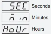 (Default : Seconds) |
| Select PV or SP for Recorder Transmission | 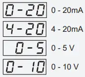 (Default : Process Value) |
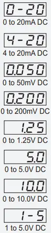
| Recorder Output Type | 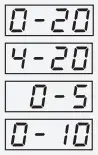 0 – 20mA 0 – 20mA4 – 20mA 0 – 5 V 0 – 10 V (Default : 0 to 20mA) |
| Recorder Low | Min. to Max. Range Specified for the Selected Input Type (Default : -199) |
| Recorder High | Min. to Max. Range Specified for the Selected Input Type (Default : 1376) |
ALARM PARAMETERS
| Parameters | Settings (Default Value) |
| Alarm-1 Type |  None NoneProcess Low Process High Deviation Band Window Band (Default : None) |
| Alarm-1 Setpoint | Min. to Max. Range specified for the selected Input Type (Default : Min or Max Range) |
| Alarm-1 Deviation Band | Min. to Max. Range specified for the selected Input Type (Default : Min or Max Range) |
| Alarm-1 Window Band | 3 to 999 (Default : 5) |
| Alarm-1 Hysteresis | 1 to 999 (Default : 2) |
| Alarm-1 Inhibit |  (Default : No) |
| Alarm-2 Type |  None NoneProcess Low Process High Deviation Band Window Band (Default : None) |
| Alarm-2 Setpoint | Min. to Max. Range specified for the selected Input Type (Default : Min or Max Range) |
| Alarm-2 Deviation Band | -999 to 999 or -999.9 to 999.9 (Default : 5) |
| Alarm-2 Window Band | 3 to 999 (Default : 5) |
| Alarm-2 Hysteresis | 1 to 999 (Default : 2) |
| Alarm-2 Inhibit | 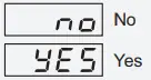 (Default : No) |
PROFILE CONFIGURATION PARAMETERS
| Parameters | Settings (Default Value) |
| Enabling Profile Feature | 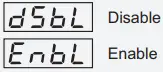 (Default : Disable) |
| Number of Segments | 1 to n (n = 4, 8, 12 or 16 depending on factory configuration) (Default : n) |
| Number of Repeats | 1 to 9999 (Default : 1) |
| Common Holdback |  (Default : Yes) |
| Output Off |  (Default : No) |
| ‘Power Fail Recovery’ Strategy |  (Default : Continue) |
PROFILE SETTING PARAMETERS
| Parameters | Settings (Default Value) |
| Segment Number | 1 to n (n = 4, 8, 12 or 16 depending on factory configuration) (Default : 1) |
| Target Setpoint | Min. to Max. Range specified for the selected Input Type (Default : -199) |
| Time Interval | 0 to 9999 Minutes (Default : 0) |
| Holdback Type |  (Default : None) |
| Holdback Value | 1 to 999 (Default : 1) |
OPERATOR PAGE PARAMETERS
| Parameters | Settings (Default Value) |
| End of Profile Acknowledge |  (Default : No) |
| Profile Start Command |  (Default : No) |
| Profile Abort Command |  (Default : No) |
| Profile Pause Command | (Default : No) |
| Segment Skip Command | (Default : No) |
| (De)Activate Standby Mode | (Default : No) |
| Control Setpoint | Setpoint Low Limit to Setpoint High Limit (Default : -199) |
| Auxiliary Control Setpoint Alarm-1 Setpoint | Setpoint Low Limit to Setpoint High Limit (Default : -199) Throughout the range for the selected Input Type (Default : For Process Low : -199 For Process High : 1376) |
| Alarm-1 Deviation Band | -999 to 999 (Default : 5) |
| Alarm-1 Window Band | 3 to 999 (Default : 5) |
| Alarm-2 Setpoint | Throughout the range for the selected Input Type (Default : For Process Low : -199 For Process High : 1376) |
| Alarm-2 Deviation Band | -999 to 999 (Default : 5) |
| Alarm-2 Window Band | 3 to 999 (Default : 5) |
PROFILE STATUS INFORMATION
| Lower Readout Prompt | Upper Readout Information |
| Active Segment Number | |
Segment Type | |
| Target Setpoint | |
| Ramping Setpoint | |
| Balance Time | |
| Balance Repeats |
ON-LINE ALTERATION PARAMETERS
| Parameters | Effect on the running segment |
| Time Interval | RAMP:- Altering the time interval shall immediately affect the ‘Ramp Rate’ forthe current segment. SOAK:- Elapsed time so far is ignored and the soak timer starts counting down to 0 from the altered time interval value. |
| Holdback Type | The modified Holdback Band Type is applied immediately on the current segment. |
| Holdback Value | The modified Holdback Band Value is applied immediately on the current segment. |
| Balance Repeats | The modified repeats become the new target repeats with immediate effect. |
TABLE- 1
| Option | Range (Min. to Max.) | Resolution |
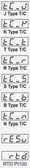 | 0 to +960°C / +32 to +1760°F | Fixed 1°C / 1°F |
| -200 to +1376°C / -328 to +2508°F | ||
| -200 to +385°C / -328 to +725°F | ||
| 0 to +1770°C / +32 to +3218°F | ||
| 0 to +1765°C / +32 to +3209°F | ||
| 0 to +1825°C / +32 to +3218°F | ||
| 0 to +1300°C / +32 to +2372°F | ||
| Reserved for customer specific Thermocouple type not listed above. | ||
| -199 to +600°C / -328 to +1112°F or -199.9 to 600.0°C / -199.9 to 999.9°F | User settable 1°C / 1°F or 0.1°C / 0.1°F | |
 | -1999 to +9999 units | User settable 1 / 0.1 / 0.01/0.001 units |
FRONT PANEL LAYOUT
EPSILON 96X96
| Symbol | Key | Function |
| PAGE | Press to enter or exit set-up mode. |
| DOWN | Press to decrease the parameter value. Pressing once decreases the value by one count; keeping pressed speeds up the change. |
| UP | Press to increase the parameter value. Pressing once increases the value by one count; holding pressed speeds up the change. |
| ENTER | Press to store the set parameter value and to scroll to the next parameter on the PAGE. |
ELECTRICAL CONNECTIONS
SERIAL COMMUNICATION MODULE
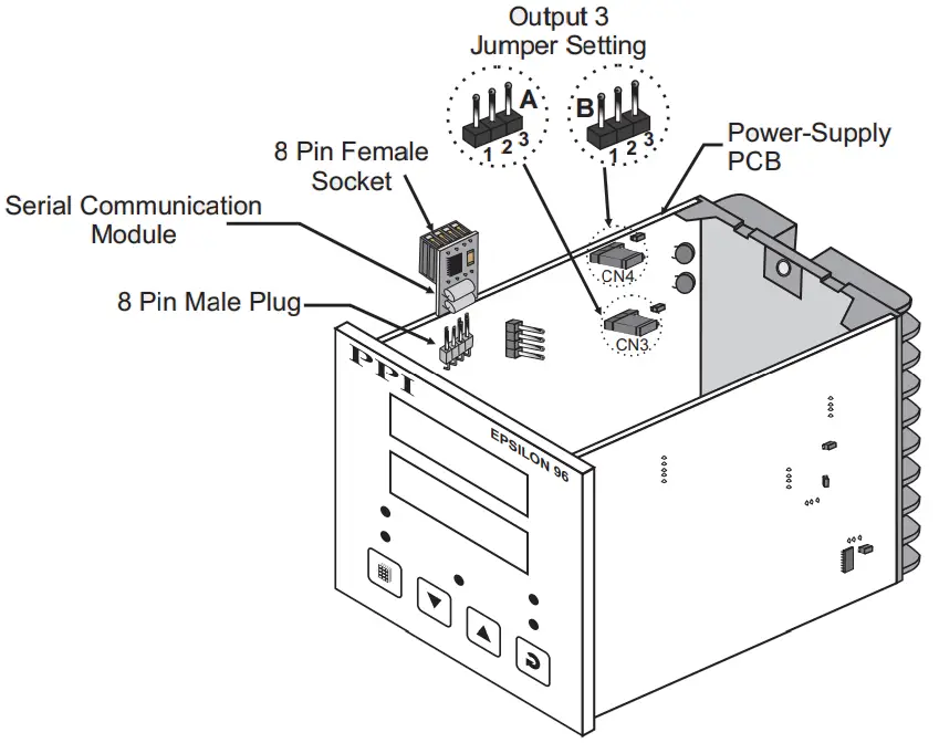
INPUT & OUTPUT HARDWARE JUMPER SETTINGS
![]() 101, Diamond Industrial Estate, Navghar,
101, Diamond Industrial Estate, Navghar,
Vasai Road (E), Dist. Palghar – 401 210.
Sales : 8208199048 / 8208141446
Support : 07498799226 / 08767395333
E: [email protected],
[email protected]
Jan 2022


