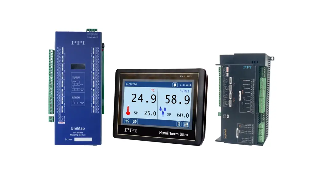
![]() Temperature + Humidity (%RH) Control & Recording System
Temperature + Humidity (%RH) Control & Recording System
with 8 / 16 Mapping Inputs
Instruction Manual
HumiTherm Ultra Temperature Humidity %RH Control and Recording System
Operation Manual
This brief manual is primarily meant for quick reference to wiring connections and parameter searching. For more details on operation and application; please log on to www.ppiindia.net
| Level | Sub-Level | Parameters | Range (Default) | |||||||||||||||||||||||||
| Temperature Set Value | Temp. Setpoint Low Limit to Temp. Setpoint High Limit (Default : 25.0 °C) | |||||||||||||||||||||||||||
| Temperature Low Deviation Alarm | 0.2 to 99.9 °C (Default : 2.0 °C) | |||||||||||||||||||||||||||
| Temperature High Deviation Alarm | 0.2 to 99.9 °C (Default : 2.0 °C) | |||||||||||||||||||||||||||
| %RH Set Value | %RH Setpoint Low Limit to Temp. Setpoint High Limit (Default : 60.0 %) | |||||||||||||||||||||||||||
| %RH Low Deviation Alarm | 0.2 to 99.9 % (Default : 2.0 %) | |||||||||||||||||||||||||||
| %RH High Deviation Alarm | 0.2 to 99.9 % (Default : 2.0 %) | |||||||||||||||||||||||||||
| SP Edit on Home Screen | Enable Disable | |||||||||||||||||||||||||||
| Recording Interval | 1 to 250 Minutes (Default : 5 Minutes) | |||||||||||||||||||||||||||
| ‘Delete Record’ Command | NA | |||||||||||||||||||||||||||
| Calendar Date (DD/MM/YY) | NA | |||||||||||||||||||||||||||
| Clock Time (HH:MM:SS) | NA | |||||||||||||||||||||||||||
| GSM Machine ID | 1 to 128 (Default : 1) | |||||||||||||||||||||||||||
| Reset GSM Module | NA | |||||||||||||||||||||||||||
| Lock Position (On / Off) | Solenoid ON Solenoid OFF (Default : Solenoid OFF) | |||||||||||||||||||||||||||
| Password Entry | NA | |||||||||||||||||||||||||||
| ‘Switch Main/Standby Outputs’ | NA | ||||||||||||||||||||||||||
| ‘Switch to Standby Sensors’ | NA | |||||||||||||||||||||||||||
| Repair Acknowledge ‘Control Gadget’ ‘Input Sensor’ | NA | |||||||||||||||||||||||||||
& (Refer Note) | Input Type | *RTD Pt100, 0 to 20mA, 4 to 20mA, 0 to 5V, 0 to 10V, 1 to 5V (Default: For Temp. Input : RTD Pt100 For %RH Input : 0 to 5V) *Available for Temp. Input Only | ||||||||||||||||||||||||||
| Signal Range Low | 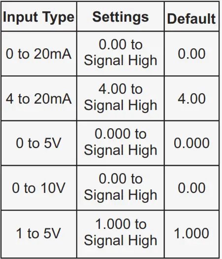 | |||||||||||||||||||||||||||
| Signal Range High | 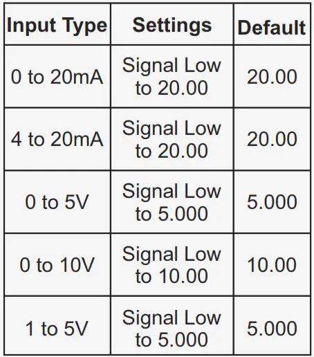 | |||||||||||||||||||||||||||
| Display Range Low | -199.9 to Range High (Default : 0.0) | |||||||||||||||||||||||||||
| Display Range High | Range Low to 999.9 (Default : 100.0) | |||||||||||||||||||||||||||
| Zero Offset | -50.0 to 50.0 (Default : 0.0) | |||||||||||||||||||||||||||
| Inhibit | Enable, Disable (Default : Enable) | |||||||||||||||||||||||||||
| Low Alarm Deviation High Alarm Deviation | 0.2 to 99.9 (Default : 2.0) | |||||||||||||||||||||||||||
| Hysteresis | 0.1 to 99.9 (Default : 0.2) | |||||||||||||||||||||||||||
| Dual Zone | ||||||||||||||||||||||||||||
| Heat Zone PID Constants Heat Zone Proportional Band | 0.1 to 999.9 °C (Default : 50.0 °C) | |||||||||||||||||||||||||||
| Heat Zone Integral Time | 0 to 3600 Sec. (Default : 100 Sec.) | |||||||||||||||||||||||||||
| Heat Zone Derivative Time | 0 to 600 Sec. (Default : 16 Sec.) | |||||||||||||||||||||||||||
| Cool Zone PID Constants Cool Zone Proportional Band | 0.1 to 999.9 °C (Default : 50.0 °C) | |||||||||||||||||||||||||||
| Cool Zone Integral Time | 0 to 3600 Sec. (Default : 100 Sec.) | |||||||||||||||||||||||||||
| Cool Zone Derivative Time | 0 to 600 Sec. (Default : 16 Sec.) | |||||||||||||||||||||||||||
| Single Zone | ||||||||||||||||||||||||||||
| Proportional Band | 0.1 to 999.9 °C (Default : 50.0 °C) | |||||||||||||||||||||||||||
| Integral Time | 0 to 3600 Sec. (Default : 100 Sec.) | |||||||||||||||||||||||||||
| Derivative Time | 0 to 600 Sec. (Default : 16 Sec.) | |||||||||||||||||||||||||||
| Single Zone & Dual Zone | ||||||||||||||||||||||||||||
| Output Cycle Time (Sec.) | 0.5 to 100.0 Sec. (Default : 10.0 Sec.) | |||||||||||||||||||||||||||
| Set Value (Temperature Control Loop) | Temp. Setpoint Low Limit to Temp. Setpoint High Limit (Default : 25.0) | |||||||||||||||||||||||||||
| Low Limit (for Temp. Control Set Value) | -199.9 to Temperature Setpoint High Limit (Default : 10.0) | |||||||||||||||||||||||||||
| High Limit (for Temp. Control Set Value) | For RTD : Temperature Setpoint Low Limit to 600.0 For mA/V : Temperature Setpoint Low Limit to 999.9 (Default : 60.0) | |||||||||||||||||||||||||||
| Self Tune | NA | |||||||||||||||||||||||||||
| Mode | Continuous OFF Continuous ON SP Based ON-OFF PV Based ON-OFF (Default : Continuous OFF) | |||||||||||||||||||||||||||
| Compressor SP | 0.0 to 100.0 (Default : 45.0) | |||||||||||||||||||||||||||
| Boundary SP | 0.0 to 100.0 (Default : 45.0) | |||||||||||||||||||||||||||
| Time Delay | 0 to 1000 Sec. (Default : 200 Sec.) | |||||||||||||||||||||||||||
| Hysteresis | 0.1 to 99.9 °C (Default : 2.0 °C) | |||||||||||||||||||||||||||
| Zone Select | Single, Dual (Default : Single) | |||||||||||||||||||||||||||
| Float Detection Enable | Yes / No (Default : No) | |||||||||||||||||||||||||||
| Float Low Level Logic | Switch Open, Switch Close (Default : Switch Close) | |||||||||||||||||||||||||||
| Thermostat Detection Enable | Yes / No (Default : No) | |||||||||||||||||||||||||||
| Thermostat Low Level Logic | Switch Open, Switch Close (Default : Switch Close) | |||||||||||||||||||||||||||
| Common Boiler | No / Yes (Default : No) | |||||||||||||||||||||||||||
| Detection Enable | No / Yes (Default : No) | |||||||||||||||||||||||||||
| Door Open Logic | Switch Open, Switch Close (Default : Switch Close) | |||||||||||||||||||||||||||
| Alarm Delay (Sec.) | 0 to 1000 Sec. (Default : 60 Sec.) | |||||||||||||||||||||||||||
| Detection Enable | No / Yes (Default : No) | |||||||||||||||||||||||||||
| Power Fail Logic | Switch Open, Switch Close (Default : Switch Close) | |||||||||||||||||||||||||||
| Temperature Low Limit for Sensor Fail Detection | 0 to 25.0 °C (Default : 0 °C) | |||||||||||||||||||||||||||
| %RH Low Limit for Sensor Fail Detection | 0 to 60.0 % (Default : 0 %) | |||||||||||||||||||||||||||
| Fail Detect Time (Min) | 0 to 250 Min. (Default : 10 Min.) | |||||||||||||||||||||||||||
| Cyclic Time (Hrs.) | 0 to 500 Hrs. (Default : 48 Hrs.) | |||||||||||||||||||||||||||
| Inhibit Time (Hrs.) | 0 to 250 Hrs. (Default : 1 Hrs.) | |||||||||||||||||||||||||||
| Select Mapping Inputs | 4T + 4RH, 8T + 8RH (Default : 4T + 4RH | |||||||||||||||||||||||||||
& (Refer Note) | Low Alarm Set Value | -199.9 to 600.0 °C (Default : 0 °C) | ||||||||||||||||||||||||||
| Low Alarm Hysteresis | 0.1 to 50.0 °C (Default : 2.0 °C) | |||||||||||||||||||||||||||
| Low Alarm Inhibit | Enable, Disable (Default : Disable) | |||||||||||||||||||||||||||
| High Alarm Set Value | -199.9 to 600.0 °C (Default : 0 °C) | |||||||||||||||||||||||||||
| High Alarm Hysteresis | 0.1 to 50.0 °C (Default : 2.0 °C) | |||||||||||||||||||||||||||
| Low Alarm Inhibit | Enable, Disable (Default : Disable) | |||||||||||||||||||||||||||
| Input Type | *RTD Pt100, 0 to 20 mA, 4 to 20 mA, 0 to 50 mV, 0 to 200 mV, 0 to 1.25 V, 0 to 5 V, 1 to 5 V, 0 to 10 V (Default: For Temp. Input : RTD Pt100 For %RH Input : 0 to 5V) *Available for Temp. Input Only | |||||||||||||||||||||||||||
| Signal Range Low |
| |||||||||||||||||||||||||||
| Signal Range High |
| |||||||||||||||||||||||||||
| Display Range Low | -199.9 to Range High (Default : 0.0) | |||||||||||||||||||||||||||
| Display Range High | Range Low to 999.9 (Default : 100.0) | |||||||||||||||||||||||||||
| Zero Offset | -50.0 to 50.0 (Default : 0.0) | |||||||||||||||||||||||||||
Note
The Setting and Default Values are the same for Temperature and Humidity (%RH) parameters.
The units for Temperature is °C & that for Humidity is %.
ELECTRICAL CONNECTIONS
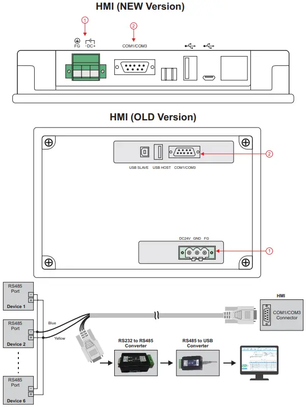
| 1 |  | 3-Pin Male / Female Connector (5.08 mm pitch) Supply Voltage : 20 to 28 VDC (24 V Nominal) |
| 2 |  | 9 Pin D Type Connector RS485 Serial Communication with Control Unit & PC |
microPLC Electrical Connections Mapping Module Electrical Connections
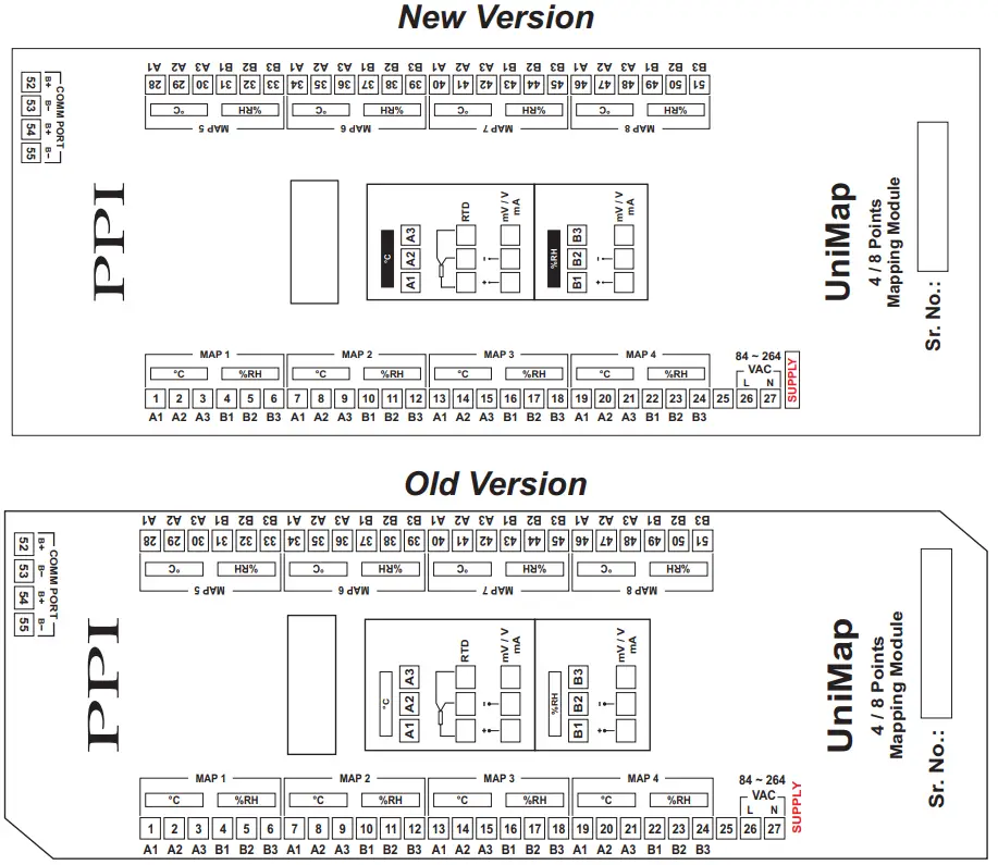
MECHANICAL MOUNTING
New Version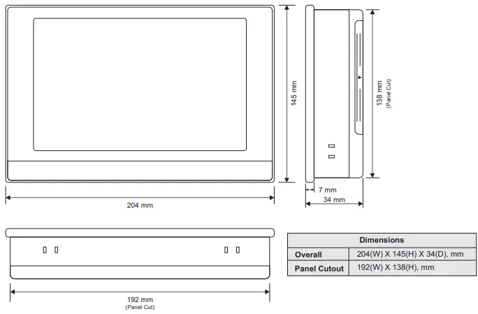 Old Version
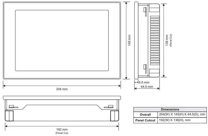 microPLC Mounting
 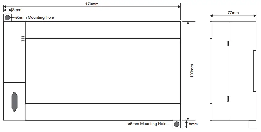 UniMap (4T + 4RH or 8T + 8RH) Mounting
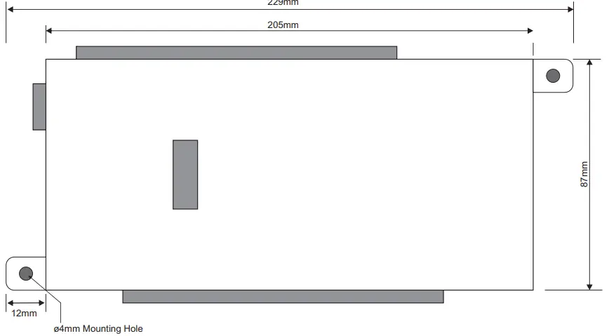
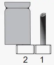
JUMPER SETTINGS
INPUT-CHANNEL INTERFACE MODULE (CIM)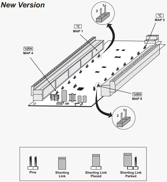
RTD Sensor
Pt100 (3-wire)
Thermocouples
J, K, T, R, S, B, N Types
DC Voltage
0-50mV, 0-200mV
0-1.25V, 0-5V, 1-5V, 0-10V
 Park Shorting Link Park Shorting Link | DC Current 0-20mA, 4-20mA 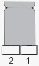 Place Shorting Place ShortingLink on Pins 1 & 2 |
Old Version
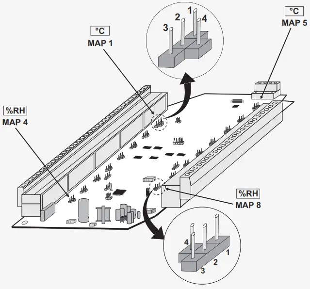 Input Type Jumper Settings For Mapping Module
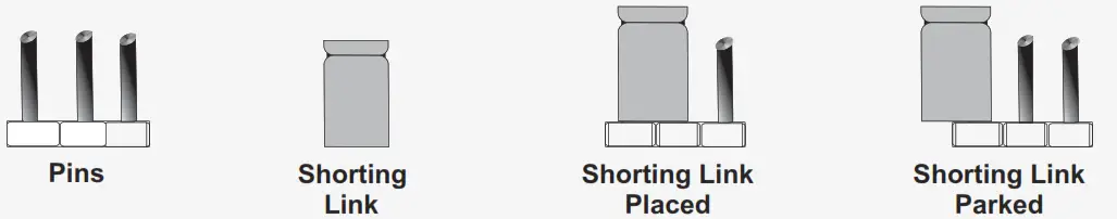 | ||
RTD Pt100 (3-wire)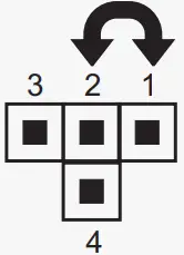 Place Shorting Place ShortingLink on Pins 1 & 2 | 0-20mA, 4-20mA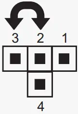 Place Shorting Place ShortingLink on Pins 2 & 3 | 0-50mV, 0-200mV, 0-1.25V, 0-5V, 1-5V, 0-10V  Park Shorting Link Park Shorting Link |
![]() 101, Diamond Industrial Estate, Navghar, Vasai Road (E), Dist. Palghar – 401 210.
101, Diamond Industrial Estate, Navghar, Vasai Road (E), Dist. Palghar – 401 210.
Sales : 8208199048 / 8208141446 Support : 07498799226 / 08767395333
E: [email protected],
[email protected]
Jan 2022


