
Elexant 450c Control Unit

Product Information
- Product Name: Elexant 450c
- Firmware Version: E2.2.0 or higher (for Elexant 450c)|
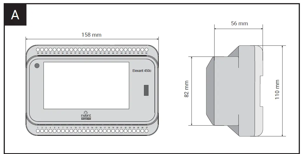
Firmware Version: E2.2.1M or higher (for Elexant 450c-Modbus) - Dimensions: 82 mm x 110 mm x 158 mm
- Supported Languages: English (EN), German (DE), French (FR), Dutch (NL), Danish (DA), Finnish (FI), Norwegian (NO), Swedish (SE), Czech (CZ), Lithuanian (LT), Polish (PL), Russian (RU), Chinese (ZH), Italian (IT)
Product Usage Instructions
- Description:
The Elexant 450c is a product that requires installation and operation. This manual provides instructions on how to install, operate, and troubleshoot the product. - Installation instructions:
- Ensure that the firmware version of your Elexant 450c is E2.2.0 or higher.
- For Elexant 450c-Modbus, ensure that the firmware version is E2.2.1M or higher.
- Follow the dimensions provided for proper installation.
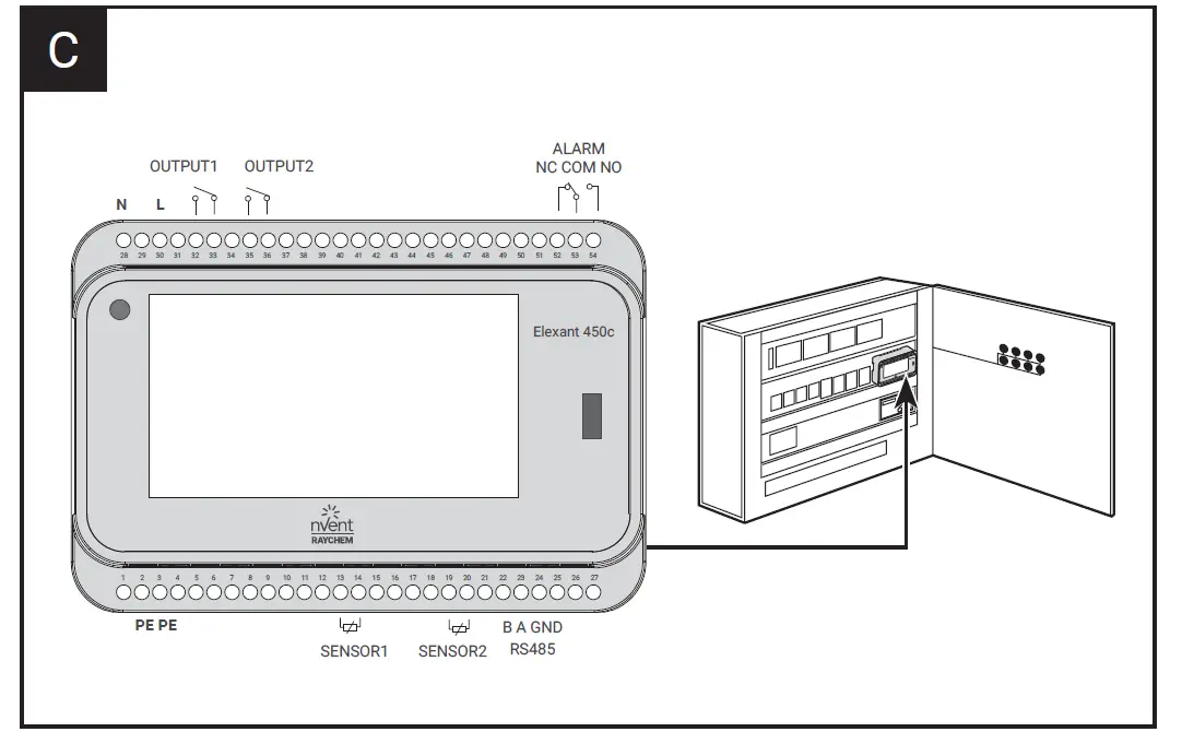
- Connect the necessary cables and sensors to the designated ports (PE, PE, B, A, GND, SENSOR1, SENSOR2, RS485).
- Refer to the specific language section for detailed installation instructions.
- Operation:
- Once the product is properly installed, refer to the language section for instructions on how to operate the Elexant 450c.
- Familiarize yourself with the different outputs and alarms indicated on the product.
- Follow the guidelines provided in the manual for efficient operation.
- Commissioning report:
After successfully installing and operating the Elexant 450c, fill out the commissioning report section to document the completion of the process. - Technical specifications:
Refer to the technical specifications section for detailed information on the product’s technical specifications. - Troubleshooting: If you encounter any issues with the Elexant 450c, refer to the troubleshooting section for possible solutions.
Please note that the instructions provided here are a summary of the user manual. For complete and detailed instructions, refer to the specific language section in the user manual corresponding to your preferred language.
Important Safeguards and Warnings
Warning: Fire and Shock Hazard
nVent RAYCHEM Elexant Systems must be installed correctly to ensure proper operation and to prevent shock and fire. Read these important warnings and carefully follow all the installation instructions.
Follow the guidelines included in this document in order to minimize the risk of electrical shock or fire and to comply with nVent’s requirements as well as agency and national electrical codes.
DESCRIPTION
nVent RAYCHEM Elexant 450c (PCN 1244-021970) is an electronic control thermostat with color touch display, advanced alarm facilities and the capability of switching 1 (standard version) or 2 (2nd heating zone: optional) independent heating zones via external contactors.
The unit is to be mounted in panels with DIN-rail for pipe freeze protection and grease line temperature maintenance of nVent RAYCHEM pipe freeze protection heating cables.
Heating cables can be controlled (switched ON/OFF) via a suitably rated contactor.
The Elexant 450c-Modbus version (PCN 1244-022623) allows flexible Modbus connectivity for remote monitoring, configuration, and integration in a Building Management System (BMS).
INSTALLATION INSTRUCTIONS
Installation and all wiring must be in accordance with applicable regulations. The device must be installed in non-hazardous areas only. Electrical connections are to be made by qualified electricians.
Attention: mistakes made when connecting the device can cause damage to the control unit. nVent is not liable for any damage caused by faulty connection and/or incorrect handling.- • Before working on the device, switch off the power supply.
- The device may only be connected and serviced by authorized, trained personnel.
- The device is designed to be connected to fixed cables only.
- When installing the device, make sure that high-voltage cables, such as the main supply and extensions do not come into contact with low-voltage cables such as sensor cables.
- Ensure the installation is made in accordance with EN60730-1.
- Local standards for electrical connection must be observed.
- If the device does not work, please first check all connections and the main power supply.
Mounting of the enclosure
This device must be installed in a housing and snapped onto a DIN rail (DIN EN 50022-35). It is designed to be mounted in electrical panels. nVent provides a wide range of panels as standard or tailor-made products.
Sensor installations
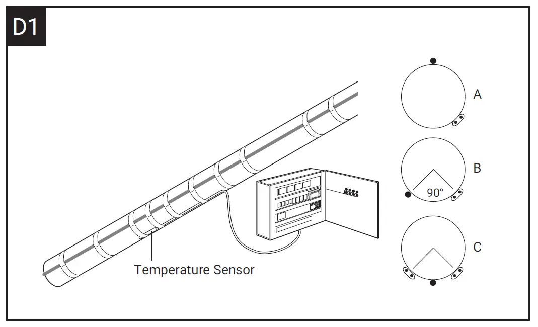
Location of the sensor: on pipe as pipe line sensor – see picture D1
- as indicated in the system design documentation
- not on valves, flanges, supports, pumps or other heat sinks
- at the top of the pipe for thermally sensitive pipe contents (A)
- on lower quadrant of pipe 90° for single heating cable (B)
- on lower quadrant of pipe centrally between the heating cables if there are two or more
Attachment of the pipe line sensor – see picture D1- fix sensor firmly on the pipe surface with adequate fixing tape (same tape as used to fix heater to the pipe)
- Fix sensor parallel to pipe
- Route sensor cable and eventual extension cable to avoid damage in use. Fix to pipe with adequate tape where appropriate
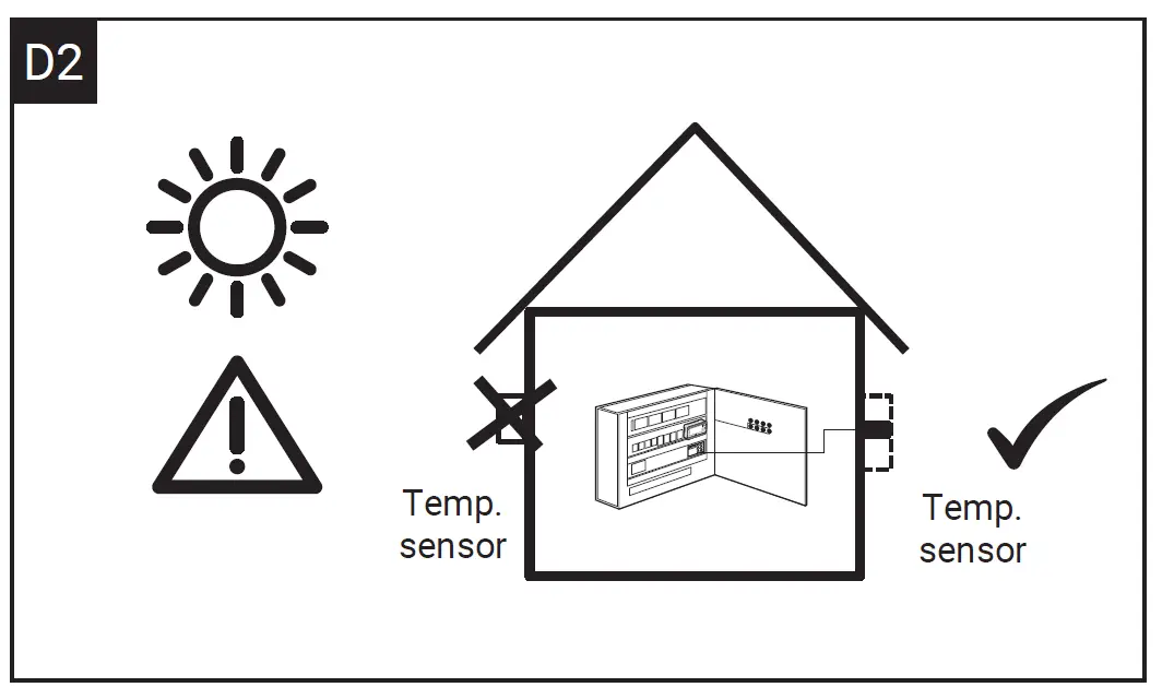
Location of the sensor: outdoor as ambient sensor – see picture D2
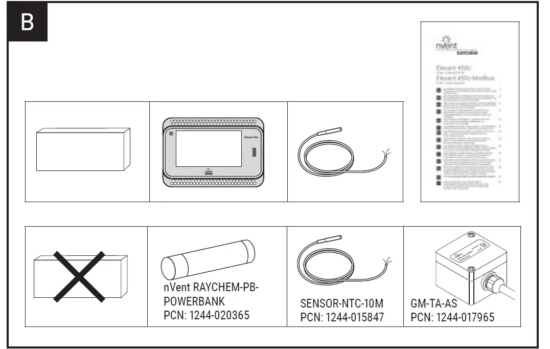
Mount the sensor in a position exposed to normal weather conditions but shielded from direct sunlight. The sensor should not be located near surfaces that are heated from within or may be heated by sunlight. It is recommended to use the sensor with housing GM-TA-AS (PCN 1244-017965) for ambient temperature detection of outdoor areas.
Warning: Do not install sensor at ambient temperatures below –20°C. Do not bend the 50 mm tip of the sensor. Min. bending radius for sensor cable: 10 mm.
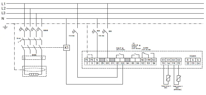
Wiring sensor to Elexant 450c
Connect the sensor cable according to the drawing for sensor 1 or sensor 2 shown in the wiring diagram (page 77/78). The unit will be provided with 1 sensor (NTC -type). A second sensor can be connected but needs to be ordered separately. Sensor-NTC-10 M (PCN 1244-015847).
Sensor extension
The sensor cable can be extended up to 150 m when a cross section of 2 x 1,5 mm² is used (max. 20 Ω per conductor). The connection between sensor cable and sensor extension can be made in junction box JB-86 or equivalent. Use a shielded cable for extension to avoid interference. The shielding / braid is to be earthed in the panel/thermostat.
Ensure that the pipe and sensor are thermally insulated and clad to the design specification after installation of the thermostat.
Sensor temperature range extension
By using the accessory item Sensor Module SM-PT100-2 (PCN 1244-022442) for connection to a PT100 type of sensor, the temperature range can be extended up to 245°C.
Modbus connection
The Elexant 450c-Modbus (PCN 1244-022623) can be connected to a Building Management System (BMS) by using MONI-RS485-WIRE (PCN 549097-000) shielded, twisted 2-core cable (max. 1000 m) for the connection master / slave and BMS.
OPERATION
If Elexant 450c / 450c-Modbus is not programmed, the unit will start a quickstart menu after powering up. For further detailed parameters and settings use the separate operation manual and the Modbus register map document. This can be downloaded from www.nVent.com/RAYCHEM.
Note: The pre-programming of the controller can be done with an external power-bank e.g. RAYCHEM-PB-POWERBANK (PCN 1244-020365) in case there is no power supply on site during controller/panel installation.
COMMISSIONING REPORT
| Elexant 450c Project location: | ||
| Elexant 450c-Modbus Date: | ||
| SERIAL-NUMBER: | ||
| PARAMETER | HEATING ZONE 1 | HEATING ZONE 2 |
| OPERATION MODE | OFF: AMBIENT: LINE: | OFF: AMBIENT: LINE: |
| SETPOINT °C | ||
| HYSTERESIS | ||
| LOW TEMP. SETPOINT | ||
| HIGH TEMP. SETPOINT | ||
| HEATER OPERATION IF SENSOR ERROR | ||
| SENSOR NUMBER | ||
| SENSOR LENGTHS | ||
| HEATING CABLE | ||
| RCD | mA | mA |
| CB TYPE | ||
| INSTALLER COMPANY | ||
| INSTALLER NAME | ||
TECHNICAL SPECIFICATIONS
| HEATING CABLES | nVent RAYCHEM freeze protection cables |
| Electrical Properties | |
| Supply voltage | 230 VAC –15/+10%; 50/60 Hz |
| Power consumption | 4 VA |
| Output relay / contactor / heating cable | 2 x 4 A / 230 VAC |
| Power supply terminals | 3 x 1,5 mm² |
| Heating cables terminals contactor | 2 x 2 x 1,5 mm² |
| Alarm terminals | 3 x 1,5 mm² |
| Sensor terminals | 2 x 2 x 1,5 mm² |
| Alarm relay | Single pole double throw relay, voltage–free, rating 2 A/250 VAC |
| Real time clock | Automatic summer/winter time and leap year correction |
| Clock back up | 10 days |
| Clock accuracy | A variation of +/– 10 min per year is possible |
| Settings | All settings are stored in a non-volatile memory |
| Exposure temperature | 0°C to +40°C |
| Storage temperature | −20°C to +50°C |
| Selectable temperature range | 0°C to +80°C (when used with SM-PT100-2 up to +245°C) |
| Enclosure | |
| Material | PPE (polyphenylene ether) |
| Dimensions | 158 mm x 110 mm x 56 mm |
| Ingress protection class | IP20 |
| Weight | 550 g |
| Mounting | DIN-Rail mountable 35 mm |
| Flammability class | D category (DIN EN60730/VDE0631-1) |
| Sensor | |||
| Standard | With SM-PT100–2 Module | ||
| (included in box) | HARD-78 | MONI-PT100–260/2 | |
| Temperature sensor type | NTC 2 kOhm / 25°C, 2-wire | PT100 | PT100 |
| Sensor tip dimensions | Ø 5 mm, length 20 mm | Ø 6 mm, length 50 mm | Ø 6 mm, length 50 mm |
| Sensor cable length | 5 m | 3 m | 2 m |
| Cable extension | Up to 150 m, cross section extension cable: 2 x 1,5 mm² | Up to 150 m, 3 x 1,5 mm² | Up to 150 m, 3 x 1,5 mm² |
| Temperature range | —40°C to +90°C see page 76 | –40°C to +150°C | –50°C to +260°C |
| Approval | |
| CE, UKCA | EMC: EN 61000-6-3, EN 61000-6-2 |
TROUBLESHOOTING
| Alarm | and error co | des : | |
| Error Code | Warning message | Problem causes | Corrective actions |
| E:2.1 | SENSOR_1_ OPEN | Sensor not connected or broken | Connect sensor to Elexant controller. Check sensor connections. Verify sensor resistance value. (see page 76) Replace sensor if defective. |
| E:2.2 | SENSOR_1_ SHORT | Sensor short | See E.2.1 |
| E:2.3 | SENSOR_2_ OPEN | Sensor not connected or broken | See E.2.1 |
| E:2.4 | SENSOR_2_ SHORT | Sensor short | See E.2.1 |
| E:3.1 | SENSOR_1_ TEMP_HIGH | Sensor 1 temperature too high | Check sensor position and actual temperature |
| E:3.2 | SENSOR_2_ TEMP_HIGH | Sensor 2 temperature too high | See E.3.1 |
| E:4.1 | SENSOR_1_ TEMP_LOW | Sensor 1 temperature too low | See E.3.1 |
| E:4.2 | SENSOR_2_ TEMP_LOW | Sensor 2 temperature too low | See E.3.1 |
| E:6.2 | INTERNAL_ ERROR | Internal error | Disconnect Elexant controller and replace unit. When reporting this error, provide the exact error number, cable type, cable length and the setpoint temperature. |
| E:6.3 | INTERNAL_ ERROR | Internal error | Disconnect Elexant controller and replace unit. When reporting this error, provide the exact error number, cable type, cable length and the setpoint temperature. |
| E:6.4 | INTERNAL_ ERROR | Internal error | Disconnect Elexant controller and replace unit. When reporting this error, provide the exact error number, cable type, cable length and the setpoint temperature. |
| – | Touch screen not responsive / Seeing 3 dots, one by one, on the screen | Pushing in the middle of the screen for 30 seconds causes controller to enter screen calibration mode (can be started also from the service menu) | All 3 dots have to be pressed one by one for calibration before jumping back to the main screen |
NTC sensor characteristic
Sensor-NTC-10M PCN: 1244-015847
GM-TA-AS PCN: 1244-017965
| NTC 2 kOhm / 25°C | Temp. | R (kOhm) |
| −40°C | 32,34 | |
| −35°C | 24,96 | |
| −30°C | 19,48 | |
| −25°C | 15,29 | |
| −20°C | 12,11 | |
| −15°C | 9,655 | |
| −10°C | 7,763 | |
| −5°C | 6,277 | |
| 0°C | 5,114 | |
| +5°C | 4,188 | |
| +10°C | 3,454 | |
| +15°C | 2,862 | |
| +20°C | 2,387 | |
| +30°C | 1,684 | |
| +40°C | 1,211 | |
| +50°C | 0,885 | |
| +60°C | 0,658 | |
| +70°C | 0,497 | |
| +80°C | 0,380 |
Standard: NTC Sensor
Option: PT100 Sensor 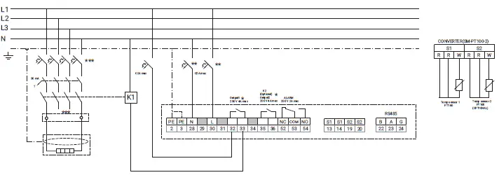
- * Output1 and output 2 can be used separately.
- ** Electrical protection by circuit breaker may be needed for local circumstances, standards and regulations.
- *** Depending on the application, one or three, or four- pole circuit breakers or contactors may be used.
België / Belgique
Tel. +32 16 21 35 02
Fax +32 16 21 36 04
[email protected]
Česká Republika
Tel. +420 606 069 618
[email protected]
Danmark
Tel. +45 70 11 04 00
[email protected]
Deutschland
Tel. 0800 1818205
[email protected]
España
Tel. +34 911 59 30 60
Fax +34 900 98 32 64
[email protected]
France
Tél. 0800 906045
[email protected]
Italia
Tel. +39 02 577 61 51
Fax +39 02 577 61 55 28
[email protected]
Nederland
Tel. 0800 0224978
[email protected]
China
Tel. +86.21.2412.1688
[email protected]
Казахстан
Tel. +7 712232 09 68
Fax +7 7122 32 55 54
[email protected]
Lietuva
Tel. +370 5 2136633
Fax +370 5 2330084
[email protected]
Norge
Tel. +47 66 81 79 90
[email protected]
Österreich
Tel. 0800 29 74 10
[email protected]
Polska
Tel. +48 22 331 29 50
Fax +48 22 331 29 51
[email protected]
Россия
Тел. +7 495 926 18 85
Факс +7 495 926 1886
[email protected]
Schweiz / Suisse / Svizzera
Tel. +41 (41) 766 3080
Fax +41 (41) 766 3081
[email protected]
Suomi
Puh. 0800 11 67 99
[email protected]
Sverige
Tel. +46 31 335 58 00
[email protected]
Türkiye
Tel. +90 545 284 09 05
Fax +32 16 21 36 04
[email protected]
United Kingdom
Tel. 0800 969 013
[email protected]
©2023 nVent. All nVent marks and logos are owned or licensed by nVent Services GmbH or its affiliates. All other trademarks are the property of their respective owners. nVent reserves the right to change specifications without notice.
RAYCHEM-IM-EU1485-Elexant450c-ML-2304 PCN 1244-022472


