![]()
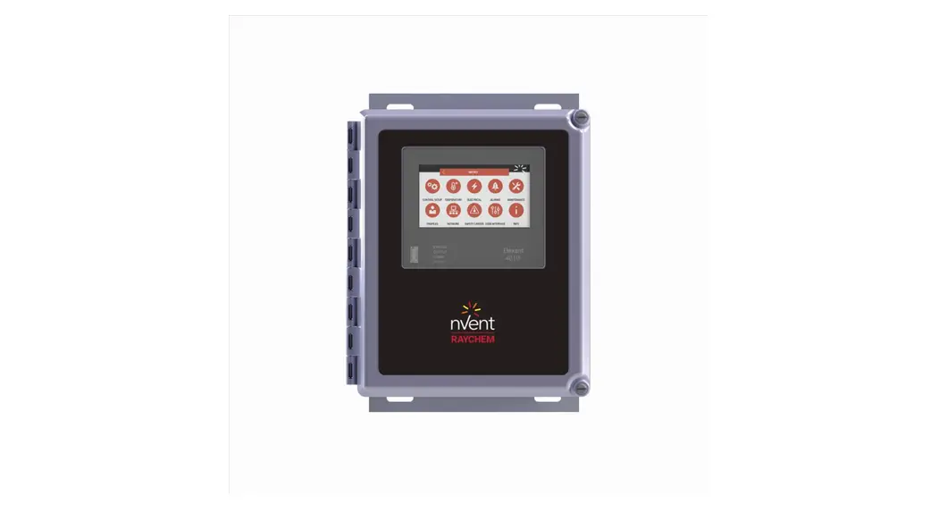
Elexant 4010i
Installation Instructions
DESCRIPTION
The nVent RAYCHEM Elexant 4010i is a compact, full-featured, touchscreen-based, single-point heat-tracing controller. It provides control and monitoring of Electric Heat Tracing (EHT) circuits for both freeze protection and process temperature maintenance. This controller can monitor and alarm on high and low temperature, high and low current, ground-fault levels, voltage, and supports a host of additional features to offer the utmost in control and monitoring of EHT.
TOOLS REQUIRED
• 3 mm head flat blade screwdriver for IO terminal
• 5 mm head flat blade screwdriver for power terminals
APPROVALS
Hazardous Locations (SSR Variants)
![]() Class I, Division 2, Group A, B, C, D T4 Type 4X
Class I, Division 2, Group A, B, C, D T4 Type 4X
Class I, Zone 2, AEx nA nC [ia Ga] IIC T4 Gc
Ex ec nC [ia Ga] IIC T4 Gc
IP64 (FW) IP66 (SW)
![]()
DEMKO 18 ATEX 2091 X
UL21UKEX2316X
II 3 (1)G Ex ec nC [ia Ga] IIC T4 Gc
IP64 (FW) IP66 (SW)
IECEx UL 18 .0098X
![]()
Non-Hazardous Locations (EMR & SSR Variants)
Enclosure Type 4X
IP64 (FW) IP66 (SW)
I.S Temperature Sensor Inputs (Optional) Associated Apparatus Entity Parameters
Um = 305VAC
Uo = 5.4V
Io = 0.083A
Ca = 65uF
La = 2mH
VARIANTS (NOT ALL VARIANTS ARE AVAILABLE IN ALL REGIONS)
| Type | Description |
| 4010i-EMR-FW | Elegant 4010i controller in an 8 in x 10 in FRP enclosure with window and 2-pole 32A EMR. Controls a single circuit with a 2-pole electromechanical relay. (Approved for non-hazardous locations only) |
| 4010i-SSR-FW | Elegant 4010i controller in an 8 in x 10 in FRP enclosure with window and 2-pole 32A 277V SSR. Controls a single circuit with a 2-pole solid-state relay. (Approved for Class I, Div. 2/Zone 2 locations) |
| 4010i-EMR-SW | Elegant 4010i controller in an 8 in x 10 in a stainless steel enclosure with window and 2-pole 32A EMR. Controls a single circuit w ith a 2-pole electromechanical relay. (Approved for non-hazardous locations only) |
| 4010i-SSR-SW | Elegant 4010i controller in an 8 in x 10 in a stainless steel enclosure with window and 2-pole 32A 277V SSR. Controls a single circuit with a 2-pole solid-state relay. (Approved for Class I, Div. 2 /Zone 2 locations) |
| 4010i-EMR-IS-FW | Elegant 4010i controller in an 8 in x 10 in FRP enclosure with window and 2-pole 32A EMR. Controls a single circuit with a 2-pole electromechanical relay. Includes intrinsically safe barriers on RTD inputs. (Approved for non-hazardous locations only. RTDs may be placed in Class I, Div.2/Zone 2 , Div.1/Zone 1 locations) |
| 4010i-SSR-IS-FW | Elegant 4010i controller in an 8 in x 10 in FRP enclosure with window and 2-pole 32A 277V SSR. Controls a single circuit with a 2-pole solid state relay. Includes intrinsically safe barriers on RTD inputs. (Approved for Class I, Div. 2/Zone 2 locations, RTDs may be placed in Class I, Div. 2/Zone 2, Div. 1/Zone 1 location) |
| 4010i-EMR-IS-SW | Elegant 4010i controller in an 8 in x 10 in a stainless steel enclosure with window and 2-pole 32A EMR. Controls a single circuit with a 2-pole electromechanical relay. Includes intrinsically safe barriers on RTD inputs. (Approved for non-hazardous locations only. RTDs may be placed in Class I, Div. 2/Zone 2 , Div. 1/Zone 1 locations) |
| 4010i-SSR-IS-SW | Elegant 4010i controller in an 8 in x 10 in a stainless steel enclosure with window and 2-pole 32A 277V SSR. Controls a single circuit with a 2-pole solid-state relay. Includes intrinsically safe barriers on RTD inputs. (Approved for Class I, Div. 2 /Zone 2 locations, RTDs may be placed in Class I, Div. 2/Zone 2, Div.1/Zone 1 locations) |
| 4010i-Mod | Elegant 4010i Module (replacement) |
| 4010i-Mod-IS | Elegant 4010i Module with IS Barrier (replacement) |
![]() WARNING:
WARNING:
This component is an electrical device that must be installed correctly to ensure proper operation and to prevent shock or fire.
2 | nVent.com/RAYCHEM
GENERAL
| Supply voltage | 100Vac to 277Vac, +/–10%, 50-60Hz |
| Internal power consumption | < 24W |
| Electromagnetic Compatibility | IEC 61326-1:2012 / EN 61326-1:2013 |
ENVIRONMENTAL
| Protection | Type 4X, IP64 (FRP enclosure) Type 4X, IP66 (stainless steel enclosure) |
| Materials | Fiber-Reinforced Plastic (FRP) or stainless steel (SS304) |
| Ambient operating temperature | –40°C to 60°C (–40°F to 140°F) |
| Ambient storage temperature | –55°C to 85°C (–67°F to 185°F) |
| Relative humidity | 0% to 90%, noncondensing |
| Environment | PD2, CAT III |
| Max altitude | 2,000 m (6,562 ft) |
CONTROL
| Relay Type | Double-pole, mechanical (EMR versions) Double-pole, solid-state (SSR versions) |
| Voltage, maximum | 277Vac nominal, 50/60Hz |
| Current, maximum | 32A @ 40°C, de-rated to 24A @ 50°C and further de-rated to 16A @ 60°C (EMR) 32A @ 40°C, de-rated to 24A @ 50°C and further de-rated to 16A @ 60°C (SSR) |
TEMPERATURE SENSOR INPUTS
| Quantity | Three temperature inputs each of which can be individually set to one of the types below. |
| Types | |
| 100Ω platinum RTD | 3-wire, α=0.00385 ohms/ohm/°C Can be extended with a 3-conductor shielded cable of 20Ω maximum per conductor |
| 100Ω nickel-iron RTD | 2-wire, α=0.00599 ohms/ohm/°C Can be extended with a 2-conductor shielded cable of 20Ω maximum per conductor |
| 100Ω nickel RTD | 2-wire, α=0.00618 ohms/ohm/°C Can be extended with a 2-conductor shielded cable of 20Ω maximum per conductor |
| Thermocouple | Requires an external 4-20mA converter 4-20mA current loop, ±0.05mA, 24Vdc loop power provided in the device, external loop power can also be used |
Intrinsic Safety Barriers included on RTD Inputs when using IS models.
RTD Intrinsic Safety Associated Apparatus Entity Parameters
| Uo (Maximum Output Voltage): 5.4V | La (Maximum External Inductance): 2mH |
| Io (Maximum Output Current): 0.083A | Ca (Maximum External Capacitance): 65uF |
| Po (Maximum Output Power): 0.449W |
DIGITAL INPUTS
| Quantity | Two multi-purpose inputs for connection to external dry (voltage free) contact or DC voltage |
| Rating | 100 Ω max loop resistance or 5-24Vdc @ 1 mA maximum |
OUTPUTS
| Alarm Relay | Form-C dry contact: | 100Vac to 277Vac, 3A, 50/60Hz |
| Auxiliary Output | 24Vdc, max load of 250 mA @ 40°C, de-rated to 165 mA @ 60°C | |
CONNECTION TERMINALS
| Power Supply Input | Screw terminals, 24 – 5 AWG (0.2 – 16.8 mm 2 ) |
| Heating Cable output | Screw terminals, 24 – 5 AWG (0.2 – 16.8 mm 2 )Three box lugs, 14 – 2 AWG (2.0 – 33.6 mm 2 ) |
| Torque Range for Screw Terminals | 1.2 – 1.5 Nm |
| Sensor / Other terminals | Cage clamp terminals, 28 – 12 AWG (0.08 – 3.3 mm 2 ) |
| Minimum Conductor Temp. Rating | 80°C |
MOUNTING
| FRP enclosure with EMR | Surface mounting with four holes on 6.0 in x 10.9 in (152 mm x 278 mm) centers Hole diameter: 0.3 in (8 mm) |
| FRP enclosure with SSR | Surface mounting with four holes on 5.6 in x 11.0 in (143 mm x 279 mm) centers Hole diameter: 0.3 in (8 mm) |
| Stainless steel enclosure with EMR | Surface mounting with four holes on 6.0 in x 11.0 in (152 mm x 279 mm) centers Hole diameter: 0.3 in (8 mm) |
| Stainless steel enclosure with SSR | Surface mounting with four holes on 5.6 in x 11.0 in (143 mm x 279 mm) centers Hole diameter: 0.3 in (8 mm) |
CONNECTIONS AND INDICATORS
A. TB1 Wiring
| Terminals | Function |
| 1 | TS1 (White) |
| 2 | TS1 (Red) |
| 3 | TS1 (Red) |
| 4 | TS2 (White) |
| 5 | TS2 (Red) |
| 6 | TS2 (Red) |
| 7 | TS3 (White) |
| 8 | TS3 (Red) |
| 9 | TS3 (Red) |
| 10 | No Connect |
| 11 | No Connect |
| 12 | No Connect |
B. TB2 Wiring
| Terminals | Function |
| 1 | TC3+ |
| 2 | TC2+ |
| 3 | TC1+ |
| 4 | TC3– |
| 5 | TC2– |
| 6 | TC1– |
| 7 | – No Connect |
| 8 | SSR– |
| 9 | SSR+ |
| 10 | DIGITAL INPUT COM |
| 11 | DIGITAL INPUT 1 |
| 12 | DIGITAL INPUT 2 |
| 13 | RS485 IN+ |
| 14 | RS485 IN– |
| 15 | RS485 COM |
| 16 | RS485 OUT+ |
| 17 | RS485 OUT– |
| 18 | RS485 COM |
C. TB1 Wiring
| Terminals | Function |
| 1 | 24V+ OUT |
| 2 | – No Connect |
| 3 | Output Relay |
| 4 | 24V COM |
| 5 | External Jumper Required |
| 6 | External Jumper Required |
| 7 | Alarm_NC |
| 8 | Alarm _COM |
| 9 | Alarm_NO |
D. TB4 Wiring
| Terminals | Function |
| 1 | END |
| 2 | POWER IN (L1) |
| 3 | POWER IN (L2/N) |
| 4 | LOADOUT (L1) |
| 5 | LOADOUT (L2/N) |
![]() WARNING: Shock Hazard.
WARNING: Shock Hazard.
Disconnect from live voltage prior to accessing terminals
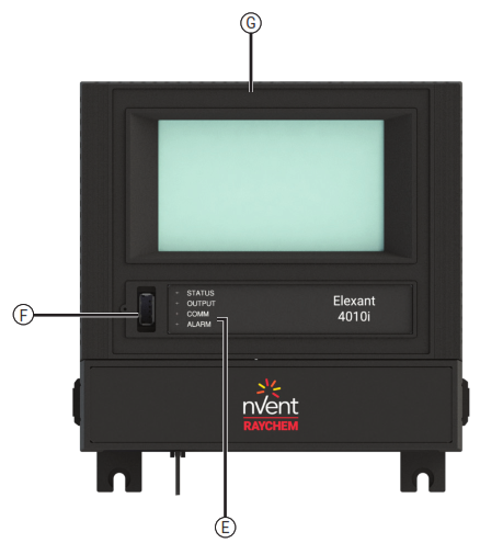
E. Status LEDs
| Status: | Indicates the status of Elexant 4010i module |
| Off | No power |
| Green | Normal operation, no internal faults |
| Red | Device Reset |
| Flash R/G | Unlocked/Calibrated |
| Output | Shows status of switched output |
COMM
| Flash Green | Receive Active |
| Flash Red | Transmit Active |
Alarm
| Red | Illuminates when an alarm is present |
F. USB Connector
G. Ethernet Connection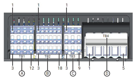
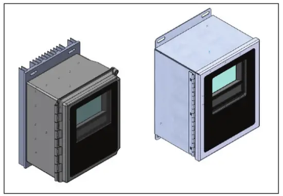
MOUNTING THE ELEXANT 4010i CONTROLLER
- SSR version should ideally be mounted to channel strut to maximize heat sink ventilation.
- EMR version can be mounted against a flat surface using the attached mounting feet.
- Secure the enclosure using the upper and lower mounting slots in the heat sink or the mounting feet using hex head screws, flat & lock-washers washers or equivalent hardware.
SSR version
SAE ¼” x 2″ long (Grade 2, 5, 8 : Torque to 4 ft-lb, 7 ft-lb, 9ft-lb respectively)
Metric 6 mm x 50 mm (Grade 4.6, 8.8 : Torque to 6-Nm 12-Nm respectively)
EMR version
SAE ¼” x ¾” long
Metric 6 mm x 20 mm
[inches] mm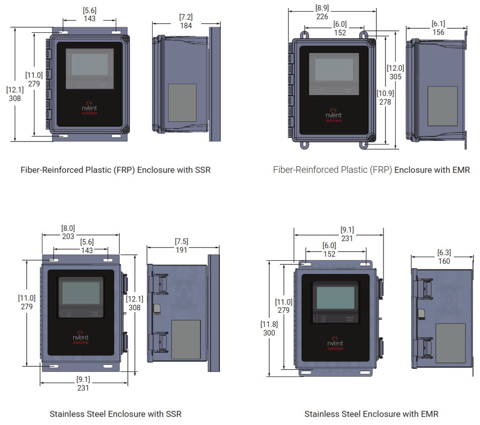
INPUT POWER
The input power connection is made at the screw terminals on TB-4.
Refer to the Connections section on page 3 for terminal block details.
The incoming ground connection should be terminated on the field terminal block located on the mounting plate.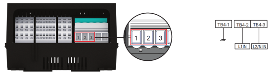
LOAD CONNECTIONS
Connections made to the load using screw terminals on TB4.
All variants use the same output connection.
Refer to the Connections section on page 3 for terminal block details.
Load ground terminations are to be made on the field terminal block located on the mounting plate.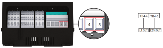
3-WIRE RTD CONNECTIONS
Terminate RTD field wires to terminal block TB1.
Refer to the Connections section on page 3 for terminal block details.
Terminate cable shields on the field terminal block located on the mounting plate.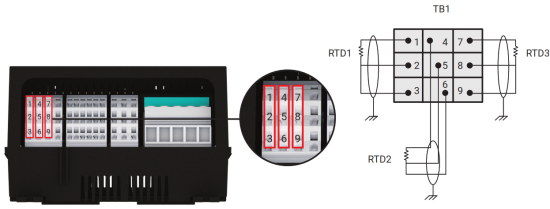
2-WIRE RTD CONNECTIONS
Terminate RTD field wires to terminal block TB1.
Refer to the Connections section on page 3 for terminal block details.
Terminate cable shields on the field terminal block located on the mounting plate.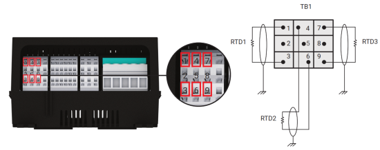
4-20 MA CONNECTIONS
Wiring for 4-20 mA connections are made directly to the terminal block TB2.
Refer to the CONNECTIONS section on page 3 for terminal block details.
Terminate cable shields on the field terminal block located on the mounting plate.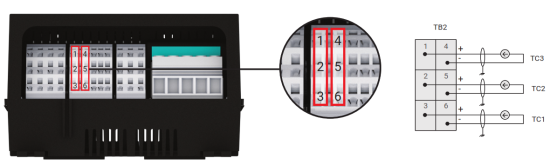
ALARM RELAY
The multi-purpose alarm relay is energized in the normal state (No Alarms) and is configured as Fail-Safe.
The alarm relay connections provide a Form-C dry contact, rated at 277 V max (3 A).
Refer to the CONNECTIONS section on page 3 for terminal block details.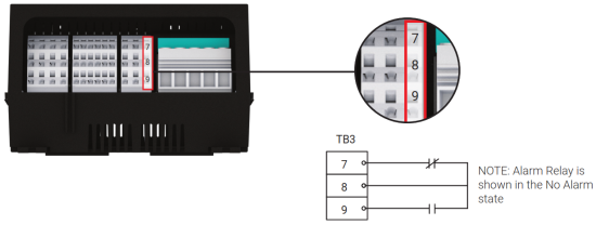
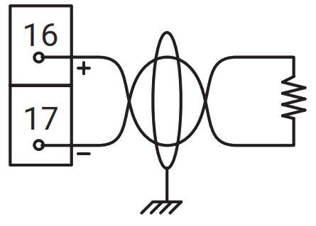
RS-485 IN
Wiring for RS-485 communications must be made directly to the terminal block TB2.
No shield wires should be terminated on the terminals of TB2.
Refer to the Connections section on page 3 for terminal block details.
Terminate cable shields on the field terminal block located on the mounting plate.
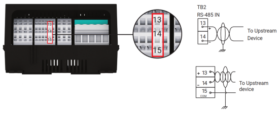 For best performance, an additional third signal ground wire is connected between COM and the signal ground of the upstream device. This wiring method will reduce noise-induced through ground potential differences.
RS-485 OUT
Wiring for RS-485 communications must be made directly to the terminal block TB2.
No shield wires should be terminated on the terminals of TB2.
Refer to the Connections section on page 3 for terminal block details.
Terminate cable shields on the field terminal block located on the mounting plate.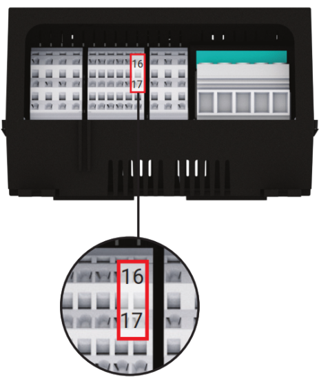
TB2
RS-485 OUT
 To next device or install a 120-ohm termination resistor
Note: Install a 120-ohm termination resistor as shown if this is the last device in the communications bus
ETHERNET
An Ethernet connection is made via the RJ45 connector using a CAT 5E cable, terminated with an RJ45 connector.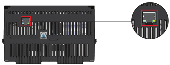
DIGITAL INPUTS
| Digital Inputs | Multi-purpose input for connection to external dry (voltage free) contact or DC voltage. |
| Rating | 100 Ω max loop resistance or 5-24 Vdc @ 1 mA maximum |
Refer to the CONNECTIONS section for terminal block details.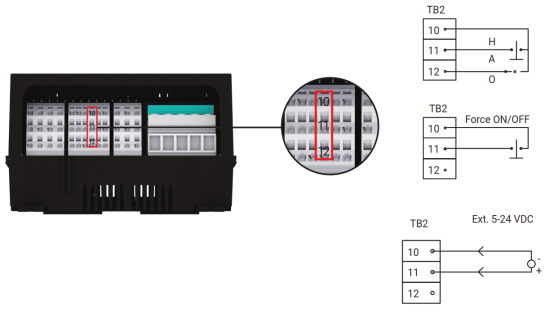
AUX 24V OUTPUT
This 24VDC output may be used to power peripheral equipment if required. The connection is made using TB3.
Refer to the CONNECTIONS section on page 3 for terminal block details.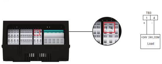
USB CONNECTOR
The USB connector on the front of the unit can be used to import and export User setting configurations for ease of programming units and uploading of new firmware.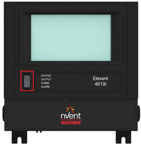
INTRINSIC SAFETY RTD CONNECTIONS – IF EQUIPPED
For models that include Intrinsic Safety barriers for the RTD connections, the terminal block TB1 will be blue. Each RTD wiring pair is to be considered a separate circuit.
RTD1 Circuit: TB1-1, TB1-2, TB1-3
RTD2 Circuit: TB1-4, TB1-5, TB1-6
RTD3 Circuit: TB1-7, TB1-8, TB1-9
Associated Apparatus Entity Parameters
Uo (Maximum Output Voltage): 5.4V
Io (Maximum Output Current): 0.083A
Po (Maximum Output Power): 0.449W
La (Maximum External Inductance): 2mH
Ca (Maximum External Capacitance): 65uF
The output current of this associated apparatus is limited by a resistor such that the output voltage-current plot is a straight line drawn between the open-circuit voltage and short-circuit current.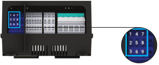
Intrinsically Safe RTD Terminal Connection
 Specific Conditions of Use
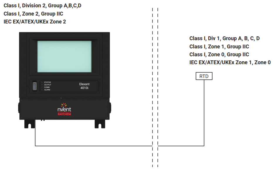 Specific Conditions of Use
This associated apparatus is intended for connection only to simple apparatus as defined in:
• Article 504.2 and installed and temperature classified in accordance with Article 504.10(D) of the National Electrical Code (ANSI/NFPA 70)
• Clause 3.5.5 and installed and temperature classified in accordance with Clause 16.4 of IEC 60079-14
• Section F3 in Appendix F and installed and temperature classified in accordance with Section F4.2 in Appendix F of the Canadian Electrical Code, Part 1 (C22.1)
• Or other local codes, as applicable.
When connecting to simple apparatus, the cable length shall not exceed 3000m (9842ft).
Associated apparatus must be installed in an enclosure suitable for the application in accordance with the National
Electrical Code (ANSI/NFPA 70) for installation in the United States, the Canadian Electrical Code for installations in Canada, or other local codes, as applicable.
The associated apparatus must be connected to a suitable ground electrode per the National Electrical Code (ANSI/ NFPA 70), the Canadian Electrical Code or other local installation codes, as applicable. The resistance of the ground path must be less than 1 ohm.
Where multiple circuits extend from the same piece of associated apparatus, they must be installed in separate cables or in one cable having suitable insulation. Refer to Article 504.30(B) of the National Electrical Code (ANSI/NFPA 70) and Instrument Society of America Recommended Practice ISA RP12.06 for installing intrinsically safe equipment.
Intrinsically safe circuits must be wired and separated in accordance with:
- Article 504.20 of the National Electrical Code (ANSI/NFPA 70)
- Clause 16.2 of IEC 60079-14
- Section F4.2 in Appendix F of the Canadian Electrical Code, Part 1 (C22.1)
- or other local codes, as applicable.
This associated apparatus has not been evaluated for use in combination with another associated apparatus.
Control equipment must not use or generate more than 305 V RMS (Um) or dc with respect to earth. - The enclosure of the device shall be fitted with a locking mechanism such that it is only accessible with the use of a tool.
- Provisions shall be made, external to the apparatus, to provide the transient protection device to be set at a level not exceeding 140% of the rated voltage at the input terminals of this apparatus.
- To maintain an internal pollution degree 2 environments, after opening the enclosure, make sure there is no visible condensation or dust. Power the device and let it heat up for 5 minutes before closing the enclosure door.
- Only install in areas with a low risk of mechanical impact.
- 4010i-Mod and 4010i-Mod-IS replacement modules must be installed into existing ATEX/UKEx/IECEx Zone 2 certified Elexant 4010i enclosures.
![]() WARNING: Explosion Hazard – Substitution of components may impair suitability for Class I, Division 2 hazardous and non-hazardous locations
WARNING: Explosion Hazard – Substitution of components may impair suitability for Class I, Division 2 hazardous and non-hazardous locations![]() WARNING: Explosion Hazard – Do not disconnect equipment unless power has been switched off or the area is known to be nonhazardous
WARNING: Explosion Hazard – Do not disconnect equipment unless power has been switched off or the area is known to be nonhazardous![]() WARNING: Explosion Hazard – To prevent the risk of electrostatic discharge, only clean the equipment enclosure with a damp cloth
WARNING: Explosion Hazard – To prevent the risk of electrostatic discharge, only clean the equipment enclosure with a damp cloth
The Elegant 4010i contains no user-serviceable parts. Contact your nVent representative for service and a Return Authorization number if required.
North America
nVent
899 Broadway
Redwood City, CA 94063
United States
Tel +1.800.545.6258
Fax +1.800.527.5703
[email protected]
Europe, Middle East, Africa
nVent
Romeinse straat 14
3001 Leuven
Belgium
Tel +32.16.213.511
Fax +32.16.213.604
[email protected]
| North America Tel +1.800.545.6258 Fax +1.800.527.5703 [email protected] | Asia Pacific Tel +86.21.5426.2937 Fax +86.21.2412.1688 [email protected] |
| Europe, Middle East, Africa Tel +32.16.213.511 Fax +32.16.213.604 [email protected] | Latin America Tel +1.713.868.4800 Fax +1.713.868.2333 [email protected] |
©2022 nVent. All nVent marks and logos are owned or licensed by nVent Services GmbH or its affiliates. All other trademarks
are the property of their respective owners. nVent reserves the right to change specifications without notice.
RAYCHEM-IM-H59271-Elexant4010i-EN-2202
nVent.com/RAYCHEM


 Electronic Thermostat User Manual")


