![]()
Elexant 9200i
Wireless Communications Interface
Installation Instructions
DESCRIPTION
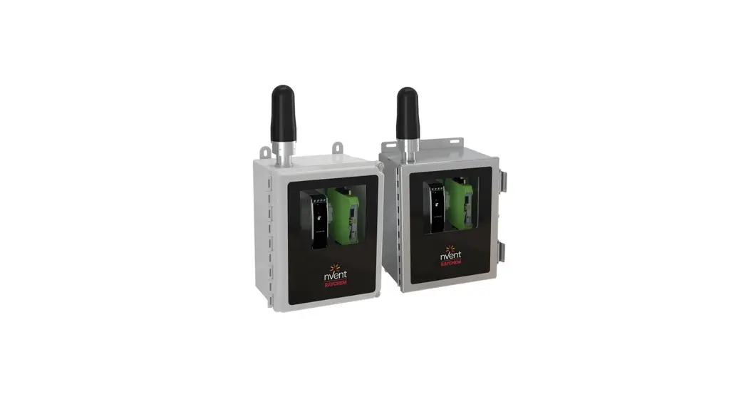
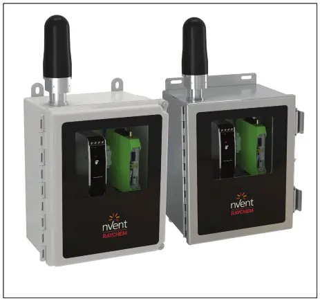
The nVent RAYCHEM Elexant 9200i is a Wireless Communications Interface that provides an alternative solution to hardwired Remote Monitoring and Configuration of Electric Heat Tracing (EHT) systems. It integrates with nVent RAYCHEM Supervisor software and Electric Heat Trace (EHT) controllers, helping reduce TIC/TOC of a project.
The Elexant 9200i product line consists of the following:
- Standalone enclosures
- A wireless communications option within a given Control Panel
- External antenna packages
A minimum of two radio transceivers are required to establish a network. Standalone enclosures can be configured in many ways, enabling the customer to choose from a range of options:
enclosure material, radio frequency, and antenna type.
TOOLS REQUIRED
Small flat-blade screwdriver (terminal driver), wire strippers and utility knife, and/or wire cutters.
SUPPORTING INFORMATION
Further information pertaining to transceiver hardware and software can be found within associated manufacturer’s documentation.
APPROVALS
Areas of Use Class I, Division 2 / Zone 2 Hazardous locations
Approvals (applicable to Enclosures) Hazardous Locations
![]() Class I, Division 2, Group A,B,C,D T4
Class I, Division 2, Group A,B,C,D T4
Class I, Zone 2, IIC T4
Type 4X
IP64 (FW), IP66 (SW)
E490519
Proc. Cont. Eq.
For Haz.Loc
![]() IECEx UL 20.0056 X Ex ec IIC T4 Gc IP64 (FW), IP66 (SW)
IECEx UL 20.0056 X Ex ec IIC T4 Gc IP64 (FW), IP66 (SW)
DEMKO 20 ATEX 2376 X
UL21UKEX2318X
II 3G Ex ec IIC T4 Gc IP64 (FW), IP66 (SW)
VARIANTS (NOT ALL VARIANTS ARE AVAILABLE IN ALL REGIONS)
nVent RAYCHEM Elexant 9200i Wireless Enclosures
(See Notes 1 and 2)
| Description | Catalog Number | Part Number | Weight (kcylbs) |
| Elexant 9200i 868 MHz Phoenix Contact module in FG enclosure with window, antenna, and pre-drilled holes for power (M25) and communications (M20) | 10392-100 | 9200i-E-PC-868-FW | 3.9 / 8.6 |
| Elexant 9200i 868 MHz Phoenix Contact module in FG enclosure with window, external antenna connection, and pre-drilled holes for power (M25) and communications (M20) – antenna & coax sold separately | 10392-101 | 9200i-E-PC-868-FW-EXT | 3.2 / 7.1 |
| Elexant 9200i 868 MHz Phoenix Contact module in SS enclosure with window, antenna, and pre-drilled holes for power (M25) and communications (M20) | 10392-102 | 9200i-E-PC-868-SW | 6.7 / 14.7 |
| Elexant 9200i 868 MHz Phoenix Contact module in SS enclosure with window, external antenna connection, and pre-drilled holes for power (M25) and communications (M20) – antenna & coax sold separately | 10392-103 | 9200i-E-PC-868-SW-EXT | 6.0 / 13.2 |
| Elexant 9200i 900 MHz Phoenix Contact module in FG enclosure with window and antenna | 10392-104 | 9200i-A-PC-900-FW | 3.9 / 8.6 |
| Elexant 9200i 900 MHz Phoenix Contact module in FG enclosure with window and external antenna connection – antenna & coax sold separately | 10392-105 | 9200i-A-PC-900-FW-EXT | 3.2 / 7.1 |
| Elexant 9200i 900 MHz Phoenix Contact module in SS enclosure with window and antenna | 10392-106 | 9200i-A-PC-900-SW | 6.7 / 14.7 |
| Elexant 9200i 900 MHz Phoenix Contact module in SS enclosure with window and external antenna connection – antenna & coax sold separately | 10392-107 | 9200i-A-PC-900-SW-EXT | 6.0 / 13.2 |
| Elexant 9200i 2.4 GHz Phoenix Contact module in FG enclosure with window and antenna | 10392-108 | 9200i-A-PC-024-FW | 3.9 / 8.6 |
| Elexant 9200i 2.4 GHz Phoenix Contact module in FG enclosure with window and external antenna connection – antenna & coax sold separately | 10392-109 | 9200i-A-PC-024-FW-EXT | 3.2 / 7.1 |
| Elexant 9200i 2.4 GHz Phoenix Contact module in SS enclosure with window and antenna | 10392-110 | 9200i-A-PC-024-SW | 6.7 / 14.7 |
| Elexant 9200i 2.4 GHz Phoenix Contact module in SS enclosure with window and external antenna connection – antenna & coax sold separately | 10392-111 | 9200i-A-PC-024-SW-EXT | 6.0 / 13.2 |
| Elexant 9200i 2.4 GHz Phoenix Contact module in FG enclosure with window, antenna, and pre-drilled holes for power (M25) and communications (M20) | 10392-112 | 9200i-E-PC-024-FW | 3.9 / 8.6 |
| Elexant 9200i 2.4 GHz Phoenix Contact module in FG enclosure with window, external antenna connection, and pre-drilled holes for power (M25) and communications (M20) – antenna & coax sold separately | 10392-113 | 9200i-E-PC-024-FW-EXT | 3.2 / 7.1 |
| Elexant 9200i 2.4 GHz Phoenix Contact module in SS enclosure with window, antenna, and pre-drilled holes for power (M25) and communications (M20) | 10392-114 | 9200i-E-PC-024-SW | 6.7 / 14.7 |
| Elexant 9200i 2.4 GHz Phoenix Contact module in SS enclosure with window, external antenna connection, and pre-drilled holes for power (M25) and communications (M20) – antenna & coax sold separately | 10392-115 | 9200i-E-PC-024-SW-EXT | 6.0 / 13.2 |
nVent RAYCHEM Elexant 9200i Wireless Antenna Packages
All Antenna Packages listed are accessories to the Enclosures shown above, and are shown to assist the customer in product selection. However, they are not included in the approvals of the Enclosures. Each component of the antenna packages must have its own suitable certification for each use case. Refer to the section on ‘SPECIFIC CONDITIONS OF SAFE USE’ for further information.
(See Notes 1 and 2)
| Description | Catalog Number | Part Number | Weight (kg/lbs) |
| Elexant 9200i 868 MHz Antenna Package Accessory – OMNI 2 dBi antenna with 3 meter coaxial cable, antenna bracket, and gland | 10392-151 | 9200i-E-PC-ANT-868-0M1-3 | 1.4 / 3.1 |
| Elexant 9200i 868 – 900 MHz Antenna Package Accessory – OMNI 2 dBi antenna with 3 meter coaxial cable, antenna bracket, and gland | 10392-152 | 9200i-A-PC-ANT-900-0M2-3 | 1.4 / 3.1 |
| Elexant 9200i 2.4 GHz Antenna Package Accessory – OMNI 2 dBi antenna with 3 meter coaxial cable, antenna bracket, and gland | 10392-153 | 9200i-C-PC-ANT-024-0 M3-3 | 1.4 / 3.1 |
| Elexant 9200i 868 – 900 MHz Antenna Package Accessory – OMNI 5 dBi YAGI antenna with 3 meter coaxial cable, antenna bracket, and gland | 10392-154 | 9200i-C-PC-ANT-900-YA1-3 | 2.1 / 4.6 |
| Customized Antenna Package Accessory | 9200i-ANT-C | 9200i-ANT-C | N/A |
Notes:
- Many countries restrict the use of specific Radio Frequencies. In general, the following frequencies can be used accordingly:
a. 868 MHz – EMEAI
b. 900 MHz – North America
c. 2.4 GHz – Global - Further information pertaining to specific regional information can be found within the manufacturer’s documentation.
![]() WARNING:
WARNING:
This component is an electrical device that must be installed correctly to ensure proper operation and to prevent shock or fire.
GENERAL
| Electromagnetic compatibility | Conformance with EMC Directive’s 2004/108/EC and 2004/30/EU |
| Supply voltage | 100 – 240 VAC, 50-60 Hz |
| Internal power consumption | < 9 W (900MHz), 2W (868MHz & 2.4GHz) |
| Transmission power | < 1 W |
ENVIRONMENTAL
| Protection | NEMA 4X, IP64 (FG enclosure), IP 66 (Stainless Steel Enclosure) |
| Materials | Fiberglass (FG) or Stainless Steel (SS304) |
| Ambient operating temperature | –40°C to 47°C (–40°F to 116°F) cULus variants –40°C to 52°C (–40°F to 125°F) IECEX / ATEX / UKEx variants |
| Ambient storage temperature | –40°C to 85°C (–67°F to 185°F) |
| Relative humidity | 20% to 85% noncondensing |
| Environment | PD2, CAT III |
| Max. altitude | 2,000 m (6,562 ft) |
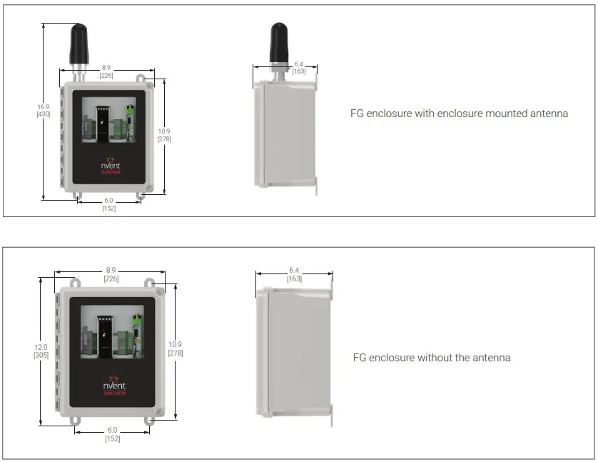
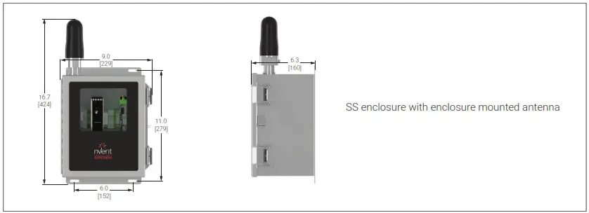
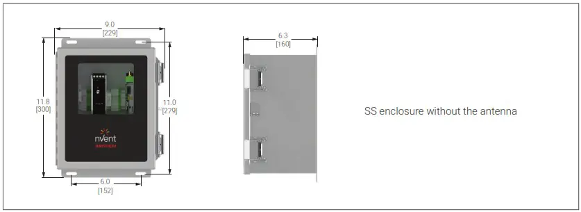
MOUNTING THE ELEXANT 9200I ENCLOSURE
The ideal mounting method is to secure the enclosure to channel strut, or other structural components, using the included mounting hardware.
Typical enclosure dimensions: inches [mm].
CONNECTIONS AND INDICATORS
| Power supply input | Fuse terminal, 26 – 10 AWG (0.14 – 6 mm2), torque 0.6 – 0.8 Nm |
| Neutral terminal, 20 – 10 AWG (0.5 – 6 mm2), cage clamp | |
| Ground (Earth), 20 – 10 AWG (0.5 – 6 mm2), cage clamp | |
| Minimum conductor temp. rating | 80°C (176°F) |
| RS-485 communications | Comm terminals, 22 – 12 AWG (0.25 – 4 mm2), cage clamp |
| Ground (Earth), 22 – 12 AWG (0.25 – 4 mm2), cage clamp |
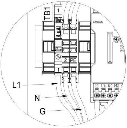
A. TB-1 Wiring
| Terminals | Function |
| 1 | Power IN (L1) |
| 2 | Power IN (N) |
| PE | Earth Ground (G) |
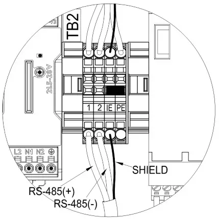
B. TB-2 Wiring
| Terminals | Function |
| 1 | RS-485 + |
| 2 | RS-485 – |
| IE NOTE1 | RS-485 Shield (SH) |
| PE | Earth Ground (G) |
Note 1: To provide isolated earth for comm shield, remove jumper between IE & PE.
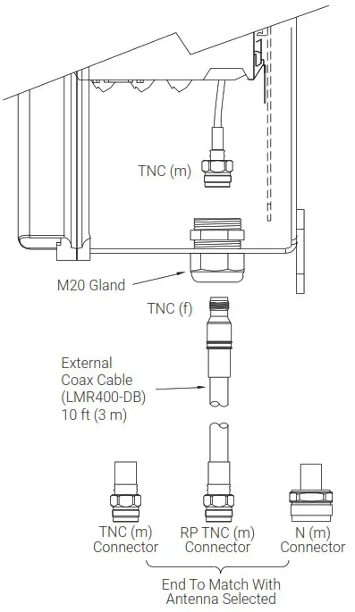
C. Antenna Connection
Note: Internal antenna connections made at factory. An external connection applies if using an external antenna package; such a connection method is provided.
D. Status LEDs – Radio transceivers
| PWR | Green LED indicating status of supply voltage |
| Off | No supply voltage present |
| On | Supply voltage OK |
| DAT | Green LED indicating status of bus communications |
| Off | No communication |
| Flashing | Unit in Configuration mode |
| On | Cyclic data communication |
![]() WARNING:
WARNING:
Shock Hazard. Disconnect from live voltage prior to accessing terminals
| ERR | Red LED indicating error state |
| Off | No error |
| Flashing – Slow (1.4 Hz) | When unit configured for I/O data mode |
| Double assignment of I/O map address | |
| Missing input module | |
| Missing output module | |
| RAD ID changed | |
| When unit configured for PLC/Modbus RTU mode | |
| Double assignment of I/O map address | |
| RAD ID changed | |
| No Modbus communication | |
| Flashing – Fast (2.8 Hz) | Wireless connection interrupted |
| On | Local bus error |
| RX | Green LED indicating Receive data activity of wireless transmissions, in conjunction with serial interface |
| TX | Green LED indicating Transmit data activity of wireless transmissions, in conjunction with serial interface |
| LED Bar Graph | Green and Yellow LEDs indicating receive signal strength | ||
| Graph status | LEDs | Receive signal | RSSI voltage |
| All 4 LEDs are lit | Connection with maximum receive signal strength | 2.5 to 3.0 V | |
| 1 Yellow LEO and 2 Green LEDs are lit | Connection with very good receive signal strength | 2.0 to 2.5 V | |
| 1 Yellow LED and 1 Green LED is lit | Connection with good receive signal strength | 1.5 to 2.0 V | |
| 1 Yellow LED lit | Connection with weak receive signal strength | 1.0 to 1.5 V | |
| All LEDs off | Not connected Configuration mode Overload | 0 VDC | |
868 MHz Radio Levels
| LED Bar Graph | 1.2k | 9.6k | 19.2k | 60k | 120k | RSSI voltage |
| -90 dBm | -85 dBm | -80 dBm | -75 dBm | -70 dBm | >= 2.5 V | |
| -100 dBm | -95 dBm | -90 dBm | -85 dBm | -80 dBm | >= 2.0 V | |
| -110 dBm | -105 dBm | -100 dBm | -95 dBm | -90 dBm | >=1.5 V | |
| LINK | LINK | LINK | LINK | LINK | -1.0V | |
| Not Connected, Configuration more, or overload | 0 V | |||||
900 MHz Radio Levels
| LED Bar Graph | 16k | 125k | 250k | 500k | RSSI voltage |
| –75 dBm | –70 dBm | –65 dBm | –60 dBm | 2.5 to 3.0 V | |
| –85 dBm | –80 dBm | –75 dBm | –70 dBm | 2.0 to 2.5 V | |
| –95 dBm | –90 dBm | –85 dBm | –80 dBm | 1.5 to 2.0 V | |
| LINK | LINK | LINK | LINK | 1.0 to 1.5 V | |
| Not Connected, Configuration more, or overload | 0 V | ||||
2.4 GHz Radio Levels
| LED Bar Graph | 16k | 125k | 250k | RSSI voltage |
| –70 dBm | –65 dBm | –60 dBm | >= 2.5 V | |
| –80 dBm | –75 dBm | –70 dBm | >= 2.0 V | |
| –90 dBm | –85 dBm | –80 dBm | >= 1.5 V | |
| LINK | LINK | LINK | ~1.0 V | |
| Not Connected, Configuration more, or overload | 0 V | |||
- INPUT POWER
The input power connection is made at the screw terminals on Terminal Block TB-1.
- RS-485 CONNECTIONS
Wiring for RS-485 communications is made at screw terminals on Terminal Block TB-2.
- ANTENNA COAXIAL CONNECTION
Depending on the package purchased, an external antenna may need to be connected.
SPECIFIC CONDITIONS OF SAFE USE
- The enclosure of the device shall be fitted with a locking mechanism such that it is only accessible with the use of a tool
- To maintain an internal pollution degree 2 environment, after opening the enclosure, make sure there is no visible condensation or dust. Power the device and let it heat up for 5 minutes before closing the enclosure door
- Only install in areas with low risk of mechanical impact
- Enclosure openings must be filled by equipment marked for use in ATEX / UKEx / IECEX Zone 2 areas, and match or exceed the IP rating of the enclosures. General Guide to Cable Entry Positions into Cable Gland or Enclosure Side:
- Maximum hole diameter is major thread diameter of cable gland plus 0.7 mm (.03″)
- Minimum material to be maintained between holes: Glands M16 through M32: 15 mm (0.59″) Glands M35 through M75: 20 mm (0.79″) Glands M75 through M100: 35 mm (1.38″). Prior to making holes in the enclosure wall or gland plate, verify that the selected gland will not interfere with the sealing washer and locknut
- Select a gland for the correct application with the proper certifications. Make certain all cable gland accessories are included for through hole installation. Additional accessories may include locknut and sealing washers
- Install the gland in accordance to the manufacturer’s instructions
- Holes must be located to prevent sealing washer and locknut from interfering with gasket
- Externally mounted antennas and accessories must be suitable for ATEX / UKEx / IECEX Zone 2 areas, and match or exceed the IP rating of the enclosures
- The fuse for incoming power shall be considered user replaceable. Refer to Enclosure Drawing Bill of Materials for the correct Current Rating, Model, and Part Number of the fuse. Prior to replacing the fuse, disable or disconnect from power.
Upon replacing the fuse, remove the fuse plug / housing, replace the fuse per note above, close and re-seat the fuse plug /housing securely
![]() WARNING: Explosion Hazard – Substitution of components may impair suitability for Class I, Division 2 hazardous and nonhazardous locations
WARNING: Explosion Hazard – Substitution of components may impair suitability for Class I, Division 2 hazardous and nonhazardous locations![]() WARNING: Explosion Hazard – Do not disconnect equipment unless power has been switched off or the area is known to be nonhazardous
WARNING: Explosion Hazard – Do not disconnect equipment unless power has been switched off or the area is known to be nonhazardous![]() WARNING: Explosion Hazard – To prevent the risk of electrostatic discharge, only clean the equipment enclosure with a damp cloth
WARNING: Explosion Hazard – To prevent the risk of electrostatic discharge, only clean the equipment enclosure with a damp cloth
| North America Tel +1.800.545.6258 Fax +1.800.527.5703 [email protected] | Europe, Middle East, Africa Tel +32.16.213.511 Fax +32.16.213.604 [email protected] | Asia Pacific Tel +86.21.5426.2937 Fax +86.21.2412.1688 [email protected] | Latin America Tel +1.713.868.4800 Fax +1.713.868.2333 [email protected] |
![]()
©2022 nVent. All nVent marks and logos are owned or licensed by nVent Services GmbH or its affiliates. All other trademarks are the property of their respective owners. nVent reserves the right to change specifications without notice.
RAYCHEM-IM-H60818-Elexant9200i-EN-2203


