nVent RAYCHEM C25-21 Power Connection Kit User Manual
C25-21
| Baseefa16ATEX0037U BAS21UKEX0506U | II 2 G Ex eb IIC Gb II 2 D Ex tb IIIC Db |
| IECEx BAS 16.0040U | U Ex eb IIC Gb Ex tb IIIC Db |
 | ТС RU C-BE.МЮ62.В.00054/18 ООО “ТехИмпорт” 1Ex e IIC Gb X Ex tb IIIC Db X Ta –55°C…+110°C IP66 |
ATEX
 | Certificate Number | Marking of IEC/IEEE 60079-30-1:2015 |
| BTV | Baseefa20ATEX0048X (BAS21UKEX0497X) IECEx BAS 20.0011X | II 2 G Ex 60079-30-1 eb IIC T6 Gb II 2 D Ex 60079-30-1 tb IIIC T80˚C Db II 2 G Ex 60079-30-1 eb mb IIC T6 Gb II 2 D Ex 60079-30-1 mb tb IIIC T80˚C Db TMin –60˚C |
| QTVR | Baseefa20ATEX0050X (BAS21UKEX0498X) IECEx BAS 20.0013X | II 2 G Ex 60079-30-1 eb IIC T4 Gb II 2 D Ex 60079-30-1 tb IIIC T130˚C Db II 2 G Ex 60079-30-1 eb mb IIC T4 Gb II 2 D Ex 60079-30-1 mb tb IIIC T130˚C Db TMin –60˚C |
| XTV | Baseefa20ATEX0049X (BAS21UKEX0499X) IECEx BAS 20.0012X | II 2 G Ex 60079-30-1 eb IIC T* Gb II 2 D Ex 60079-30-1 tb IIIC T**˚C Db II 2 G Ex 60079-30-1 eb mb IIC T* Gb II 2 D Ex 60079-30-1 mb tb IIIC T**˚C Db TMin –60˚C |
| KTV | Baseefa20ATEX0051X (BAS21UKEX0500X) IECEx BAS 20.0014X | II 2 G Ex 60079-30-1 eb IIC T* Gb II 2 D Ex 60079-30-1 tb IIIC T**˚C Db II 2 G Ex 60079-30-1 eb mb IIC T* Gb II 2 D Ex 60079-30-1 mb tb IIIC T**˚C Db TMin –60˚C |
| HTV | PTB 21 ATEX 1003 X (BAS21UKEX0649X) IECEx PTB 21.0007X | II 2 G Ex eb mb 60079-30-1 IIC 85°C (T6) .. 215°C (T2) Gb II 2 D Ex tb 60079-30-1 IIIC T85°C …T215°C Db |
| VPL (identical markings to XTV) | Baseefa20ATEX0045X (BAS21UKEX0503X) IECEx BAS 20.0008X | II 2 G Ex 60079-30-1 eb IIC T* Gb II 2 D Ex 60079-30-1 tb IIIC T**˚C Db II 2 G Ex 60079-30-1 eb mb IIC T* Gb II 2 D Ex 60079-30-1 mb tb IIIC T**˚C Db TMin –60˚C |
| Certificate N | Cod | |
| BTV | ТС RU C-BE.МЮ62.В.00054/18 | 1Ex e IIC T6 Gb X 1Ex e mb II C T6 Gb X Ex tb IIIC T80°C Db X Ex tb mb IIIC T80°C Db X Ta –60°C…+56°C IP66 |
| QTVR | ТС RU C-BE.МЮ62.В.00054/18 | 1Ex e IIC T4 Gb X 1Ex e mb IIC T4 Gb X Ex tb IIIC T130°C Db X Ex tb mb IIIC T130°C Db X Ta –60°C…+56°C IP66 |
| XTV | ТС RU C-BE.МЮ62.В.00054/18 | 1Ex e IIC T* Gb X 1Ex e mb IIC T* Gb X Ex tb IIIC T* Db X Ex tb mb IIIC T* Db X Ta –60°C…+56°C IP66 |
| KTV | ТС RU C-BE.МЮ62.В.00054/18 | 1Ex e IIC 226°C (T2) Gb X 1Ex e mb IIC 226°C (T2) Gb X Ex tb IIIC T226°C Db X Ex tb mb IIIC T226°C Db X Ta –60°C…+56°C IP66 |
| HTV | TC RU С-ВЕ.АЖ58.В.01728_21 | 1Ex e mb 60079-30-1 IIC 180°C (T3) … 215°C (T2) Gb X Ex tb 60079-30-1 IIIC 180°C … 215°C Db X Ta –60°C … +56°C I |
| VPL | ТС RU C-BE.МЮ62.В.00054/18 | 1Ex e IIC T* Gb X 1Ex e mb IIC T* Gb X Ex tb IIIC T* Db X Ex tb mb IIIC T* Db X Ta –60°C…+56°C IP6 |
 WARNING: To prevent electrical shock, short circuit or arcing, this product must be installed correctly and water ingress must be avoided before and during the installation. Before installing this product, read the installation instructions completely.
Persons involved in the installation and testing of electric trace heating systems shall be suitably trained in all special techniques required.
The purchaser should make the manufacturer aware of any external effects or aggressive substances that the equipment may be exposed to.
The cable glands shall only be used for fixed installations. The cables must be fixed to prevent pulling or twisting.
Schedule of Limitations:
The service temperature of the nVent RAYCHEM C25-21 connection kit is –55°C to +110°C. When the C25-21 connection kit is used, it shall be mounted to an enclosure in accordance with the manufacturers instructions. The installer is to carry out a dielectric strength test on the Ex equipment in which the C25-21 connection kit is fitted. No dielectric breakdown shall occur. Alternatively an insulation resistance test may be undertaken in accordance with EN 60079-30-2. Maximum Conductor Cross section 3.5 mm² Maximum Voltage 500V maximum. (Um)
| BTV | BTV | ||
| 3BTV1-CR | 3BTV2-CR | 8BTV1-CR | 8BTV2-CR |
| 3BTV1-CT | 3BTV2-CT | 8BTV1-CT | 8BTV2-CT |
| 5BTV1-CR | 5BTV2-CR | 10BTV1-CR | 10BTV2-CR |
| 5BTV1-CT | 5BTV2-CT | 10BTV1-CT | 10BTV2-CT |
| QTVR | QTVR | ||
| 10QTVR1-CT | 10QTVR2-CT | 15QTVR1-CT | 20QTVR2-CT |
| 15QTVR2-CT | 20QTVR1-CT |
| KTV | |
| 5KTV1-CT | 5KTV2-CT |
| 8KTV1-CT | 8KTV2-CT |
| 15KTV1-CT | 15KTV2-CT |
| 20KTV1-CT | 20KTV2-CT |
XTV
| 5XTV1-CT-T3 | 4XTV2-CT |
| 10XTV1-CT-T3 | 8XTV2-CT-T3 |
| 15XTV1-CT-T2 | 12XTV2-CT-T |
| 20XTV1-CT-T2 | 15XTV1-CT-T2 |
| 20XTV2-CT-T2 |
HTV
| 3HTV1-CT | 3HTV2-CT |
| 5HTV1-CT | 5HTV2-CT |
| 8HTV1-CT | 8HTV2-CT |
| 10HTV1-CT | 10HTV2-CT |
| 12HTV1-CT | 10HTV2-CT |
| 12HTV1-CT | 12HTV2-CT |
| 15HTV1-CT | 15HTV2-CT |
| 20HTV1-CT | 20HTV2-CT |
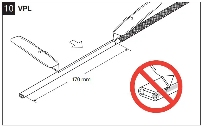
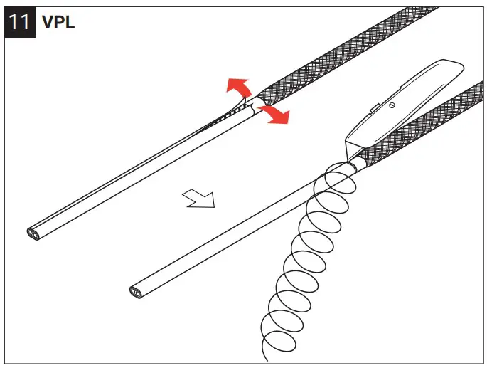
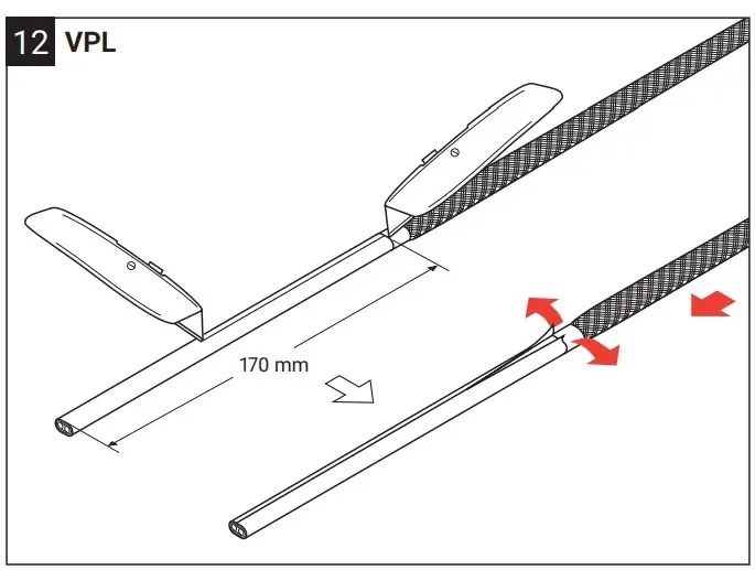
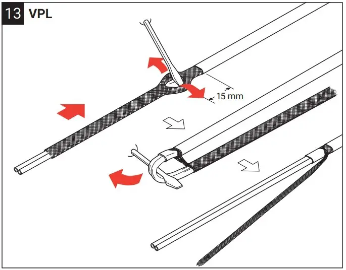
VPL
| 5VPL1-CT | 5VPL2-CT |
| 10VPL1-CT | 10VPL2-CT |
| 15VPL1-CT | 15VPL2-CT |
| 20VPL1-CT | 20VPL2-CT |
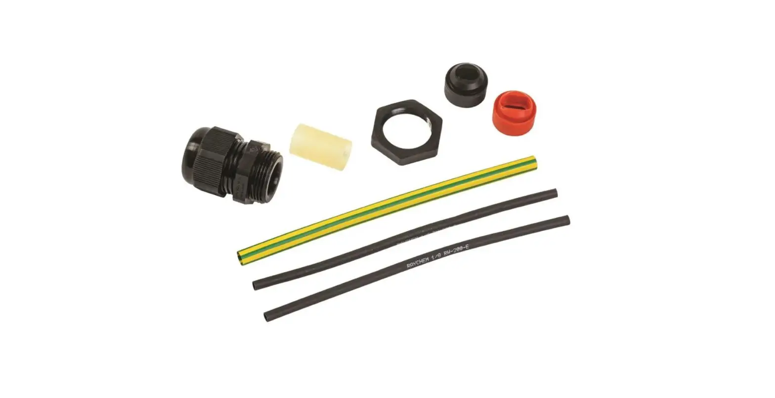
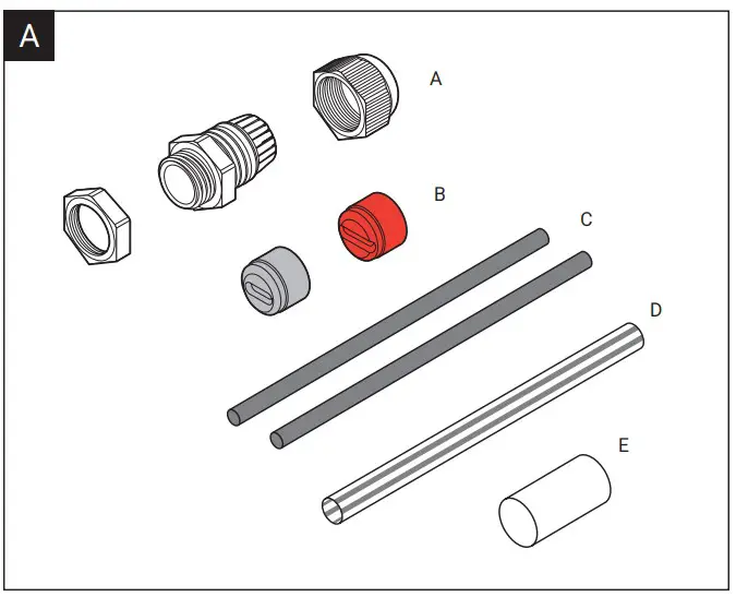
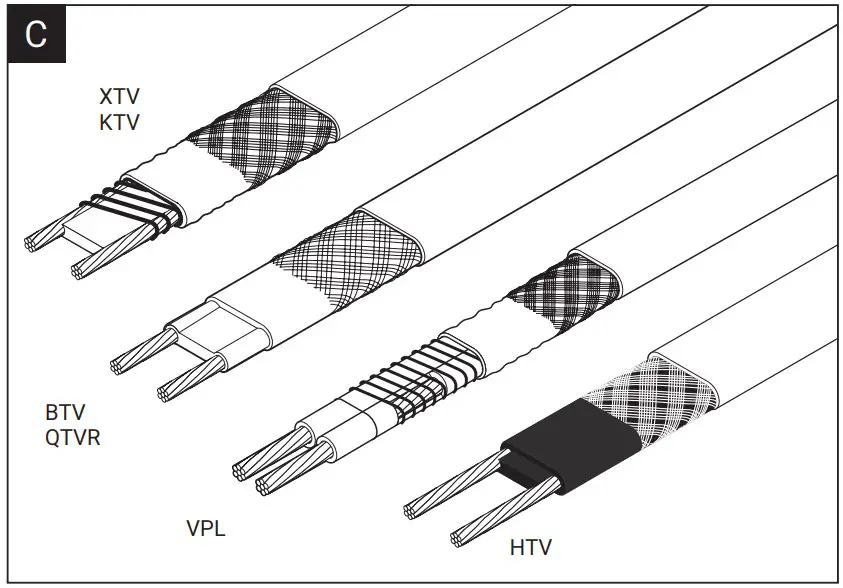
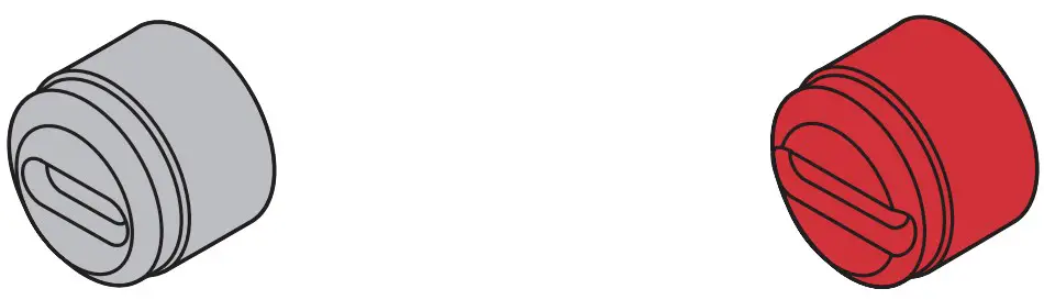
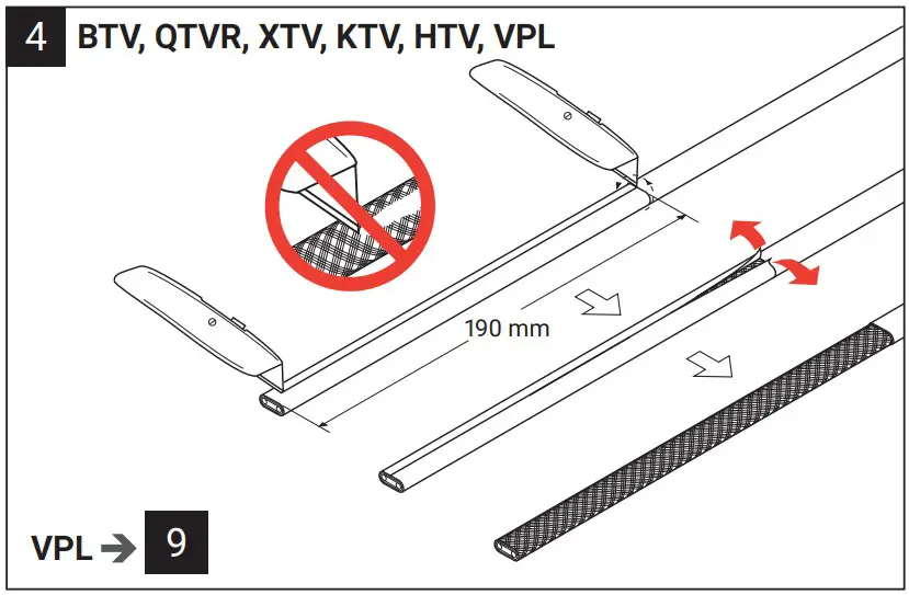
Select the correct grommet for the type of heating cable being used.
Assembly Instructions

| X | |
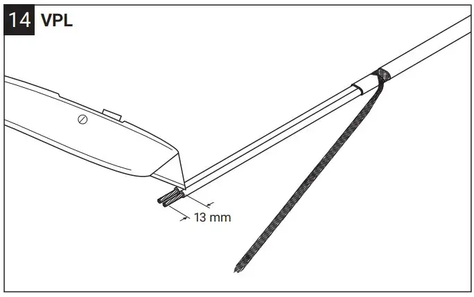
| WAGO 282/284 | 12 – 13 mm |
| Phoenix UK6N/USLKG10 | 6 m |
| Weidmüller WDU6/WPE6 | 6 mm |
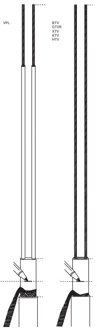
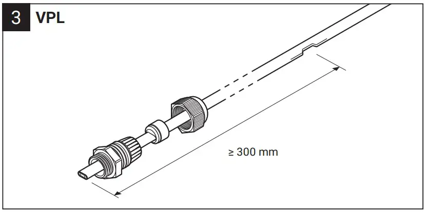
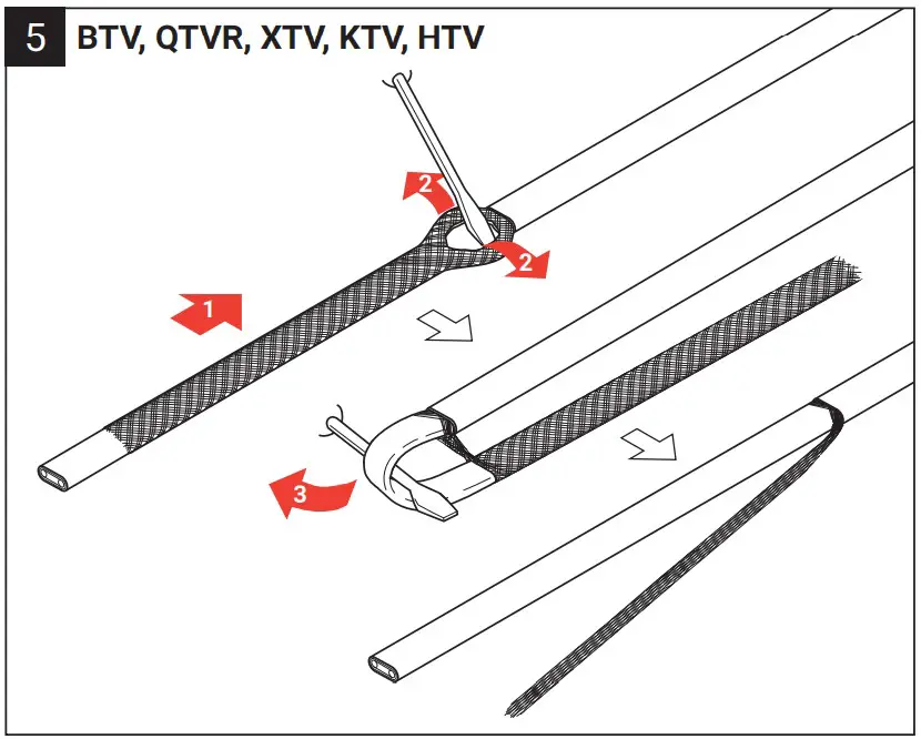
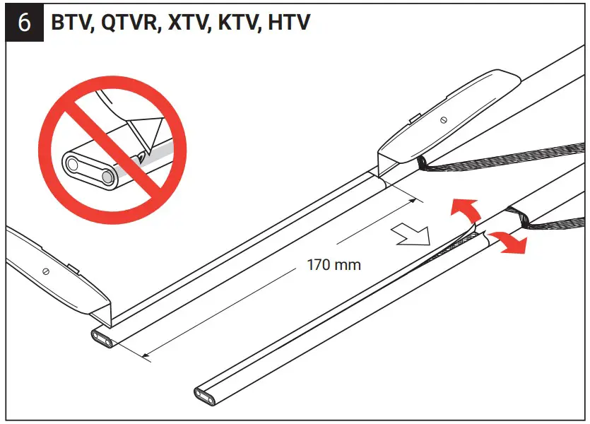
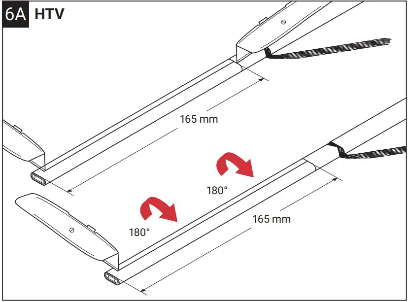
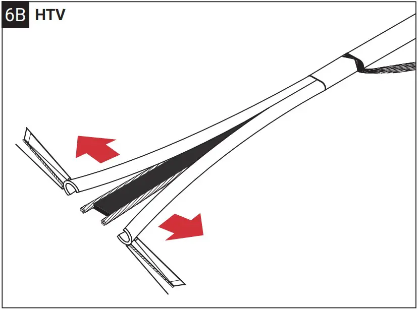
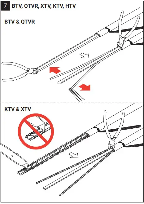
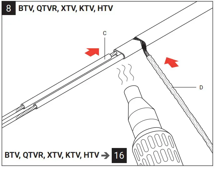
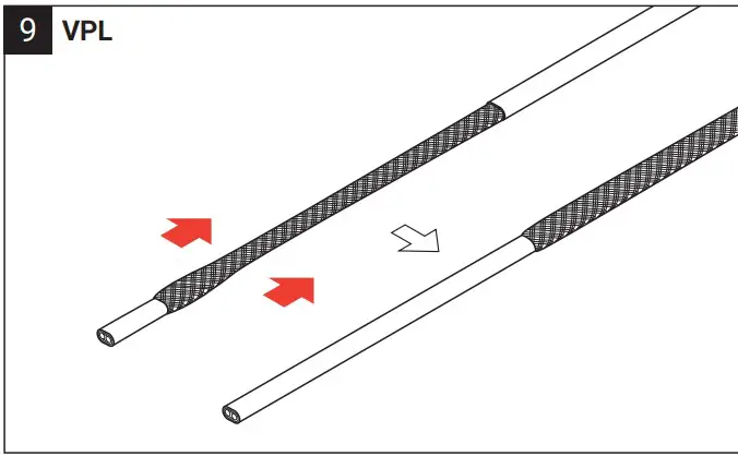
Trim bus wires and braid. For length X see table.
Installation instructions for the gland
Conditions for threaded and unthreaded holes
| Threaded Holes | Unthreaded (through) holes | |
| Tolerance Class | Tolerance class for Ex e is max. 6G/6H | Nominal thread size M25 –0,0 mm/ +0,2 mm |
| Enclosure material limitations | The plastic gland is made from flame retardant, high impact resistant polyamide | The plastic gland is made from flame retardant, high impact resistant polyamide |
| Enclosure interface sealing method | If the sealing surfaces are uneven, use PTFE washer NFWM25 or the green fiber washer GFWM25 (washers to be ordered separately) | If the sealing surfaces are uneven, use PTFE washer NFWM25 or the green fiber washer GFWM25 (Washers to be ordered separately) |
| Maximum surface roughness of the enclosure wall | Ra 6,4 µm, better than 3,2 µm is recommended | Ra 6,4 µm, better than 3,2 µm is recommended |
| Thickness range for the enclosure wall (t) | ≥ 4 mm | Minimum wall thickness: Plastic enclosures ≥ 2 mm Metal enclosures ≥ 1 mm |
| Perpendicularity | +/–1° or 0,2 mm at the outer edge of the gland, whichever is smaller | +/–1° or 0,2 mm at the outer edge of the gland, whichever is smaller |
| Permitted use and location of any eart | Earth tags should be installed on the inside of the enclosure | Earth tags should be installed on the inside of the enclosure |
| For chamfered holes | The outermost edge must not have a greater diameter than the center of the washer | The outermost edge must not have a greater diameter than the center of the washer |
| Lock nuts | Only use nVent RAYCHEM locknuts or types recommended by the manufacturer | Only use nVent RAYCHEM locknuts or types recommended by the manufacturer |
Recommended Torque Values
| Threaded Holes | Unthreaded holes with internal locknut |
| T1 = 3,0 N/m | T1 = 3 N/m |
| T2 with red grommet = 3,5 N/m | T2 with red grommet = 3,5 N/m |
| T2 with black grommet = 5 N/m | T2 with black grommet = 5 |
DE, FR, NL, NO, SV, DA, FI, IT, ES, PL, RU, CZ, HU, CRO. Page 27-40.
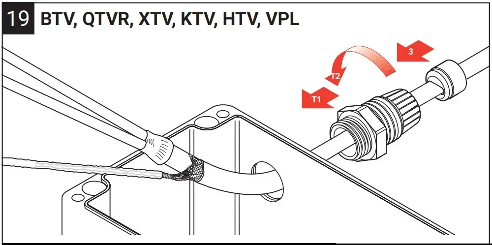
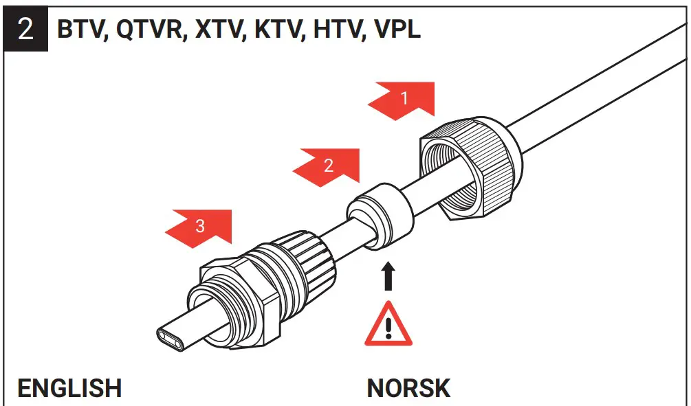
Pass prepared heating cable end with core sealer through the box entry. Screw gland body into junction box (use locknut for unthreaded boxes).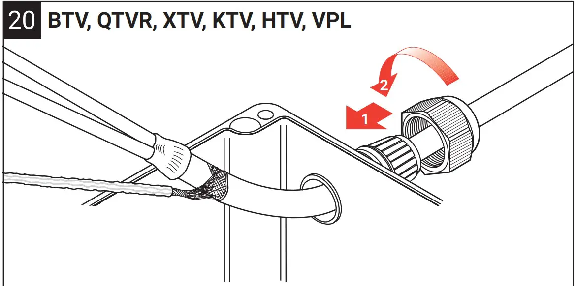
Position grommet in gland body, ensuring it is seated squarely and tighten backnut securely. Connect conductors and braid to the appropriate terminals.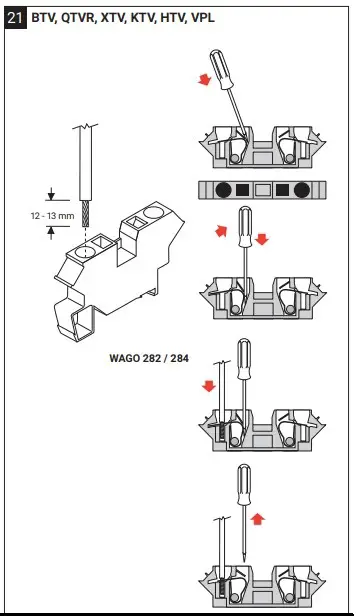
For WAGO terminals only !
België/Belgique
Tel +32 16 21 35 02
Fax +32 16 21 36 04
[email protected]
Bulgaria
Tel +359 5686 6886
Fax +359 5686 6886
[email protected]
Česká Republika
Tel +420 602 232 969
[email protected]
Danmark
Tel +45 70 11 04 00
[email protected]
Deutschland
Tel 0800 1818205
Fax 0800 1818204
[email protected]
España
Tel +34 911 59 30 60
Fax +34 900 98 32 64
[email protected]
France
Tél 0800 906045
Fax 0800 906003
[email protected]
Hrvatska
Tel +385 1 605 01 88
Fax +385 1 605 01 88
[email protected]
Italia
Tel +39 02 577 61 51
Fax +39 02 577 61 55 28
[email protected]
Lietuva/Latvija/Eesti
Tel +370 5 2136633
Fax +370 5 2330084
[email protected]
Magyarország
Tel +36 1 253 7617
Fax +36 1 253 7618
[email protected]
Nederland
Tel 0800 0224978
Fax 0800 0224993
[email protected]
Norge
Tel +47 66 81 79 90
[email protected]
Österreich
Tel 0800 29 74 10
Fax 0800 29 74 09
[email protected]
Polska
Tel +48 22 331 29 50
Fax +48 22 331 29 51
[email protected]
Republic of Kazakhstan
Tel +7 7122 32 09 68
Fax +7 7122 32 55 54
[email protected]
Pоссия
Тел. +97 495 926 18 86
Факс +7 (495) 926 18 86
[email protected]
Serbia and Montenegro
Tel +381 230 401 770
Fax +381 230 401 770
[email protected]
Schweiz/Suisse
Tel +41 (41) 766 30 80
Fax +41 (41) 766 30 81
[email protected]
Suomi
Puh 0800 11 67 99
[email protected]
Sverige
Tel +46 31 335 58 00
[email protected]
Türkiye
Tel +90 560 977 6467
Fax +32 16 21 36 04
[email protected]
United Kingdom
Tel 0800 969 013
Fax 0800 968 624
[email protected]
©2022 nVent. All nVent marks and logos are owned or licensed by nVent Services GmbH or its affiliates. All other trademarks are the property of their respective owners. nVent reserves the right to change specifications without notice. RAYCHEM-IM-INSTALL011-C2521-ML-2209