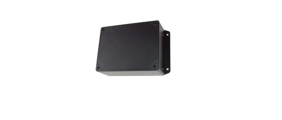
ACI MOD9200LON Network Transceiver
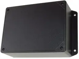
ENCLOSURE DIMENSIONS
FIGURE 1: 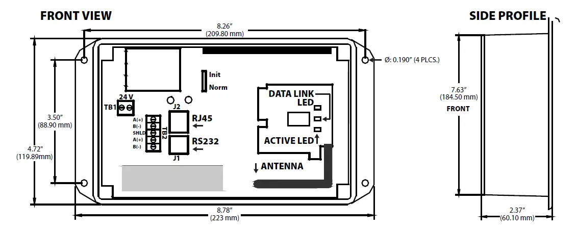
NOTE: Do not use this product in any safety related applications where human life may be affected.
GENERAL INFORMATION
ACI’s Wireless Series MOD9200LON network transceiver utilizes reliable Spread Spectrum Mesh Network Radio technology. Together with other ACI wireless sensors and controls, the system can be used to transmit remote sensor readings, status/alarm indications, control signals and outputs wirelessly. It is compatible with LON system using FTT-10 (free topology twisted pair) network wiring. Up to 50 separate physical wireless sensor transmitters and/or wireless remote output (analog & digital) modules can be used with one MOD9200LON Transceiver and up to 100 data points and 100 outputs can be monitored and controlled with one (1) MOD9200 Transceiver. The MOD9200LON is available in 6 different versions based on pre-defined sensor types and inputs. The data is in the form of SNVT’s (standard network variable type).
The maximum radio transmission distance is dependent on the building type. In a typical commercial building with steel I-Beam construction, concrete floors with reinforcing rod, and metal stud walls, it can be expected that transmissions will penetrate horizontally approximately through 200-300 feet of floor, walls, furniture and air.
Generally, a wireless system will cover at least three floors–one floor above, and one floor below the receiver location. In some buildings with favorable transmission characteristics the system may cover more floors – see FIGURE 3 (p. 2). Wireless sensor transmitters should be installed within 200 to 300 feet of the MOD9200 transceiver. RR2552 signal repeaters can be installed as needed to increase transmission distance between sensors and receivers – see FIGURE 2 (p. 2). NOTE: For best results, no more than three (3) repeaters should be installed per wireless system, and no more than two (2) repeaters in series.
PRECAUTIONS
- To maintain high performance, do not install sensors, repeaters, or receivers in the following areas:
- Inside metal enclosure / panel, inside or immediately next to elevator shaft or elevator banks
- In front of or immediately next to large trees or large body of water
MOUNTING INSTRUCTIONS
Mount the MOD9200LON near FTT-10 access point, 1’ below the ceiling, using four #8 screws.
FIGURE 2: WIRELESS BUILDING DIAGRAM
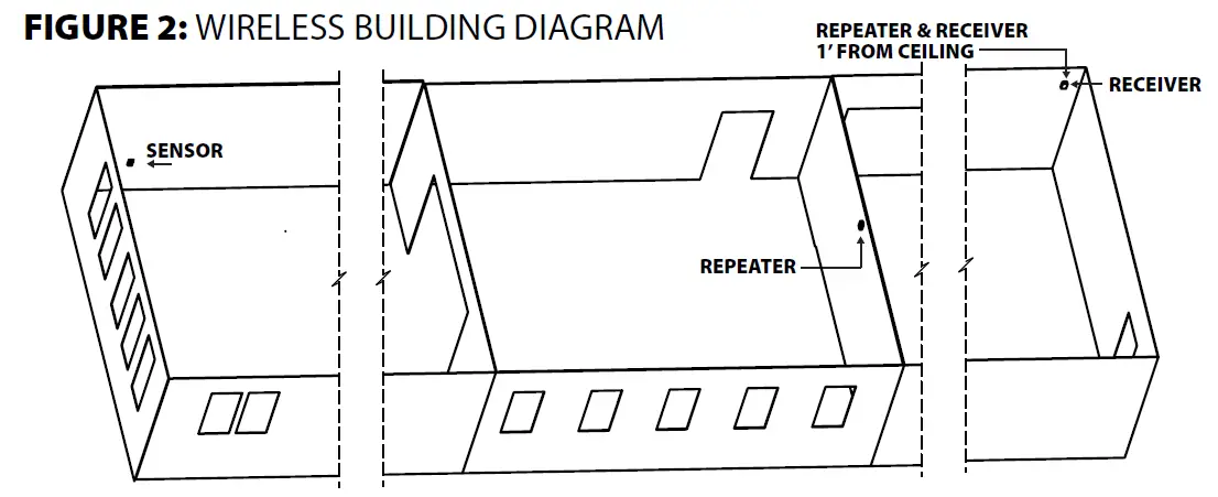
FIGURE 3: WIRELESS MULTILEVEL DIAGRAM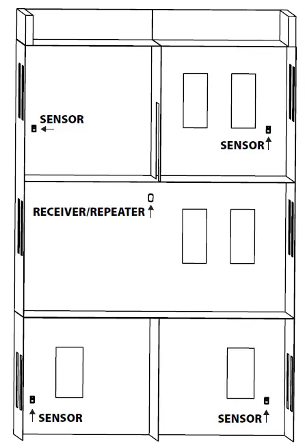
WIRING INSTRUCTIONS
WIRING PRECAUTIONS
- Do NOT run FTT-10 wiring in any conduit with line voltage (24/120/230 VAC).
- Remove power before wiring. NEVER connect or disconnect wiring with power applied.
- The MOD9200LON is full wave rectified.
- It is recommended that you use an isolated UL-listed Class 2 transformer when powering the unit with 24 VAC. Failure to wire the devices with the correct polarity when sharing transformers may result in damage to any device powered by the shared transformer.
WIRING
24VAC Input – Connect 24VAC 60Hz to the power terminal blocks (TB1 terminal) using 16 to 26 AWG twisted pair cable.
LON FFT-10
Use Eschelon® recommended 22 AWG wire or compatible cable for FTT-10 wiring. If the MOD9200LON is the only device on the bus or if it is the last device on the bus, wire the left set of “A&B” terminals – see FIGURE 4 (p. 3). If the MOD9200LON is in the middle of the bus and needs to be daisy chained, both sets of “A” and “B” terminals must be used: the left set for incoming wiring, and the right set for outgoing – see FIGURE 5 (p. 3).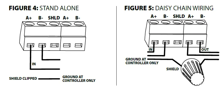 Tie the shield wires together using a wire nut and do not terminate the shield wire in the shield terminal block. The shield wire is to be grounded at the controller end only. Do not terminate the shield wire in the shield terminal block. Do not use “Star” or “T” wiring.
CONFIGURATION OF TRANSCEIVER
The sensors need to be configured to the MOD9200LON using the configuration program (included), a laptop, and a crossover cable. Refer to the user manual for programming, configuration data map, and downloading configuration program to the transceiver.
TABLE 1: STANDARD ORDERING
| MODEL # ITEM # ITEM # | ||
| MOD9200LON-A | 131048 | Up to 30 Wireless Temperature, 6 RH Sensors & 50 Wireless Digital & Analog Outputs |
| MOD9200LON-B | 131049 | Up to 50 Wireless Temperature Sensors (50 Wall/Duct/Immersion) & 50 Wireless Digital & Analog Outputs |
| MOD9200LON-C | 131050 | Up to 50 Wireless Sensors (50 Temperature & RH Points) & 50 Wireless & Analog Outputs |
| MOD9200LON-D | 131051 | Up to 50 Wireless Devices (40 0-10 VDC Point Types & Discrete Inputs, 10 Temperature & RH Points) & 50 Wireless Digital & Analog Outputs |
| MOD9200LON-E | 131052 | Up to 50 Wireless Sensors/Transmitters (26 Setpoint Adjustments, 26 Pushbutton Override Switches, 12 CO2 PPM Inputs, 6 RH Points & 4 Digital Status Inputs) & 50 Wireless Digital & Analog Outputs |
| MOD9200LON-F | – – – – – – – | Up to 50 Wireless Sensors (40 Temperature Points, 20 RH Points and 40 Discrete Inputs) & 50 Wireless Digital & Analog Outputs•IP Address of PC must have static address of 192.168.0.2 or above |
PRODUCT SPECIFICATIONS
| PRODUCT SPECIFICATIONS | |
| Supply Voltage: | 24 VAC, 60 Hz (Full wave rectified) |
| Supply Current: | 0.5A Nominal |
| Connections: | Screw Terminal Blocks |
| Wire Size: | 16 AWG (1.31 mm2) to 26 AWG (0.129 mm2) |
| Terminal Block Torque Rating: | 0.37 ft-lb (0.5 Nm) Nominal |
| Operating Temperature Range: | 32 to 122 °F (0 to 50 °C) |
| Operating Humidity Range: | 30 to 50% RH, non-condensing |
| Storage Temperature: | -4 to 176 °F (-20 to 80 °C) |
| Data Protocol: | IEEE 802, 15.4-2003/2006 |
| RF Characteristics: | 900 MHz, Operating Frequency 10 channels between 902 – 928 MHz Transmitter Power: 11 dBm | Receiver Sensitivity: -11 dBm |
| Transmission Distance: | 200 – 300 ft horizontally depending on building type and constructions, and typically one floor above and below the transceiver vertically |
| LonWorks® Protocols 1: | Temperature: SNVT_temp_p | Override Push Button: SNVT_occupancy Setpoint Adjustment: SNVT_temp_p | Humidity: SNVT_lev_percent Sensor Status/Alarms: SNVT_count PPM: SNVT_ppm The MOD9200LON Transceiver is pre-defined with fixed configurations |
| Physical Network Connection: | FTT-10 (Free Topology Twisted Pair) |
| Communication Wire: | Eschelon approved 22 AWG wire |
| Termination: | Not provided by ACI |
| Configuration Software: | Included; Data registers need to be configured prior to use |
| System Requirements: | • PC (Notebook or Laptop) with Windows 98, XP, Vista, Windows 7, or Windows 10, Ethernet port, and 10 GB of hard drive memory, direct connection from PC to MOD9200LON: RJ45 Crossover Cable (not provided by ACI) • IP Address of PC must have static address of 192.168.0.2 or above |
WARRANTY
The ACI Wireless Series are covered by ACI’s Two (2) Year Limited Warranty, which is located in the front of ACI’S SENSORS & TRANSMITTERS CATALOG or can be found on ACI’s website: www.workaci.com.
W.E.E.E. DIRECTIVE
At the end of their useful life the packaging and product should be disposed of via a suitable recycling centre. Do not dispose of with household waste. Do not burn.
Automation Components, Inc.
2305 Pleasant View Road | Middleton, WI 53562 Phone: 1-888-967-5224 | Website: workaci.com


