PENNTEK TR-25 Transceiver Kit
OVERVIEW
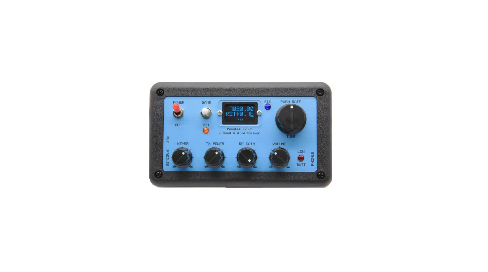
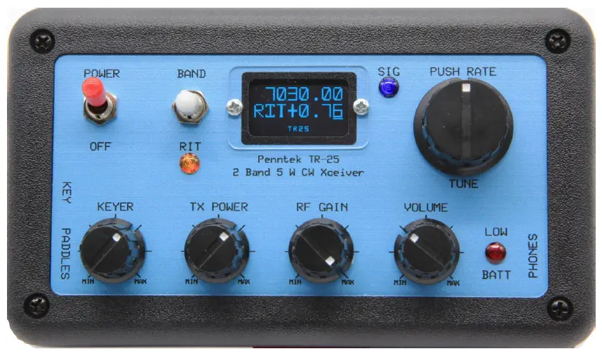
Refer to the front panel for the location of the switches and controls.
- The four rotary controls are pretty much self‐explanatory.
- There is a keyer speed control (5‐35 WPM) on the left, then the TX Power (0‐5W) adjust pot, an RF Gain control, and a Volume control.
- The Power on‐off switch in at the upper left, and the Band selector and RIT switch is to the right.
- This is a 3‐position spring return toggle switch.
- To change bands, momentarily flip this switch upward and allow it to return to the center-off position.
- Do this quickly, and the unit will switch from one band to the other.
- If you flip the switch up and hold it up for a short while, the frequency will be stored in a semi‐permanent memory.
- The display will momentarily switch to a reverse optical mode showing that the current frequency has been stored.
- There is a separate memory for each band. To recall this memory, 2 quick successive upward clicks are required.
- To engage the RIT function with this switch, a quick downward push and release of the toggle is needed.
- The orange RIT warning LED will come on, and the display will read out the offset with 10 Hz resolution as you tune.
- Another quick downward toggle will disengage the RIT function.
- The knob to the right of the blue OLED display is the tuning encoder. The frequency will change in 10 Hz, 100 HZ or 1KHz steps.
- The standard encoder will tune at 20 steps per revolution, allowing tuning rates of 200, 2k, or 20k Hz per revolution.
- If you chose the optional precision optical encoder, you can tune at 64 steps per revolution.
- The tuning step resolution is selected by a momentary switch attached internally to the tuning encoder.
- Short pushes on the tuning knob will alternate between 10 and 100 Hz tuning steps.
- A long press will enable 1 KHz steps. The frequency readout on the display will show the tuning resolution selected with an underline bar beneath the digit selected.
- The blue LED Signal indicator can be used to judge the strength of the received signal.
- A bright blue LED would indicate a strong signal. The red LED is the battery low‐level warning indicator. It will blink when the battery voltage drops below a preset level.
- The warning level is internally adjustable from 9 to 11.5 volts. An external speaker or headphones must be connected to the “Phones” jack on the right side.
- There is more than ample audio available.
- Power is connected to the DC input connector on the left side. The voltage should be between 9 and 14 volts. The center pin polarity is positive, and the pin size is 2.1mm.
- The key jack and keyer paddle jack are on the left side. Both may be connected and used randomly as you desire.
- This way, you are always ready for a new “SKCC” contact, as there is no need to reboot the transceiver in order to change from the keyer using paddles to a straight key.
- The transmitter output power is adjustable from a few milliwatts to 5 watts or more depending on the power supply.
- It should be possible to achieve the “1000 Miles per Watt” award with a station a few miles away by turning the power output down to a few milliwatts while maintaining contact! With a 10 volt supply, the output is at least 5 watts into a 50 ohm load.
- The final TO‐220 RF transistor is rugged, and has survived delivering 5 watts continuous key down of periods of more than 5 minutes.
- This is of course not recommended but illustrates the ruggedness of the transmitter design.
- The sidetone that is heard while transmitting is the actual transmitted signal being heard by the receiver.
- If you match the audio tone of the received signal to the tone of the side‐tone, you are guaranteed to be at zero beat with the station you are communicating with.


