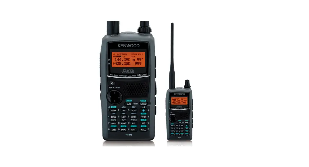
![]() TH series FM Transceiver
TH series FM Transceiver
Instruction Manual
TH series FM Transceiver
430/440 MHz FM TRANSCEIVER
TH -41A TH-41 BT TH -41 E
220 MHz FM TRANSCEIVER
TH -31A TH -31 BT
144 MHz FM TRANSCEIVER
TH -21A TH -21 BT TH -21 E
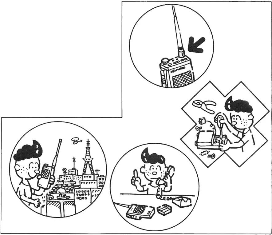
Before operation
- Ensure the supplied whip antenna is securely tightened.
- The trimmers and cores inside the unit are factories adjusted. Do not touch them.
- Should the unit require service, contact your authorized dealer.

This Instruction Manual covers the following models: Illustrations show the TH-41 BT.
TH-41 A…….. 430/440 MHz FM transceiver
TH-41 BT….. 430/440 MHz FM transceiver with DTMF
TH-41 E……. 430/440 MHz FM transceiver with 1750 Hz tone
TH-31A……… 220 MHz FM transceiver
TH-31 BT……. 220 MHz FM transceiver with DTMF
TH-21A……. 144 MHz FM transceiver
TH-21E1T ……. 144 MHz FM transceiver with DTMF
TH-21 E ……. 144 MHz FM transceiver with 1750 Hz tone
Accessories
Confirm that the accessories shown below are included.
Whip antenna………………………………………………………………………………………… 1
Ni-Cd battery pack…………………………………………………………………………………. 1
Battery charger……………………………………………………………………………………….. 1
Earphone (TH-41A/41BT/31A/31BT/21A/21BT)……………………………… 1
Hand strap………………………………………………………………………………………………. 1
Instruction Manual ……………………………………………………………………………………1
Warranty card (For users in the USA only)………………………………………………… 1
The carton box and packing materials should be retained for future transportation.
Note: The TH-31A/31BT does not operate above 224.995 MHz, since this is the upper limit of the 220 MHz band. Attempting to operate above this frequency will not produce any receive or transmit functions.
Remember the radio is designed to operate from 220.000 MHz thru and including 224.995 MHz only.
Specifications
| TH-41 A/41 RT/41 E | TH 31A/ 31 BT | TH-21A/ 21 BT | TH-21E | ||
| 430MHz version | 440MHz version | ||||
| General | |||||
| Frequency range | 430MHz to 440MHz | 440MHz to 450MHz | 220MHz to 225MHz | 144MHz to 148MHz | 144MHz to 146MHz |
| Signal type | F3 (FM) | ||||
| Operating tempera- lure | -20*C – +50t | ||||
| Antenna impedance | 5012 | ||||
| Power supply voltage | 5.8V – 10.0V (rating voltage; 7.2V) | ||||
| Power consumption | At reception standby; Less than 30 mA At transmission (Hi); Less than 650 mA (Low); About 350 mA | Less than 28 mA Less than 600 mA About 300 mA | |||
| Dimensions | W 57 (65.5) x H 120 (127.5) x D 28 (32) mm The numbers in the parenthesis include projections. | ||||
| Weight | Approx. 290 g (including antenna and Ni-Cd batteries) | ||||
| Transmitter section | |||||
| Output power | Hi; 1.0W, Low; approx. 150 mW | ||||
| Modulation system | Reactance modulation | ||||
| Max. frequency de- viation | -1-5 kHz | ||||
| Unwanted reflection | Less than -60 dB | ||||
| Microphone | Condenser type | ||||
| Receiver section | |||||
| Reception system | Double superheterodyne | ||||
| Intermediate frequency | 1st: 21.6MHz 2nd: 455kHz | 1st: 16.9MHz 2nd: 455kHz | 1st: 16.3MHz 2nd: 455kHz | ||
| Sensitivity | S/N more than 26 dB at -6dBp (0.5 j/V) input | S/N more than 28dB at -6c1Bp (0.50V) input | |||
| 12 dB SINAD; less than -12 dBp (0.25 pV) | |||||
| Squelch sensitivity | Less than 0.2pV | Less than 0.2/./V | Less than 0.25pV | ||
| Selectivity | -6 dB at more than 12 kHz -40 dB at less than 28 kHz | ||||
| AF output | More than 250 mW (80 loads, distortion 10%) | ||||
Design and specifications are subject to change without notice.
Battery notes
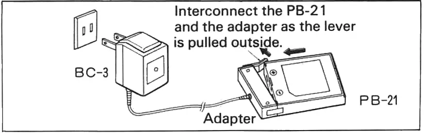
3.1. Recharging the battery pack
- Plug the BC-3 into the AC line outlet and interconnect the adapter to the battery pack PB-21. At this time, be sure of the polarities. While re-charging is correctly in progress, the red LED on the BC-3 lights. However, the LED remains lits while the BC-3 is still connected to the AC line outlet. Therefore, unplug the BC-3 after 8 hours of recharging.
Notes:
- Recharging should be done within ambient temperature between 10°C and 40°C. Recharging performed out of this range may not fully charge the battery pack.
- With excessive charging, if this happened, the battery performance and its life may lessen.

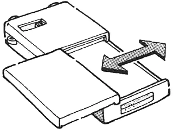
- Align the grooves in the battery case and unit and slide in the battery case to the right. Slide to the left to remove the battery case.

3.2. Operation time with AAA batteries
The operation time with a repeated 1-minute TX and 3-minute RX cycle is approximately 40 minutes with manganese batteries and about 90 minutes with alkaline manganese batteries. To communicate over a short distance, set the Hi/Low switch to LOW conserve power, and thus extend operation time. When the batteries are exhausted and the ON AIR indicator lights dimly, replace the batteries with new ones.
Controls and their functions
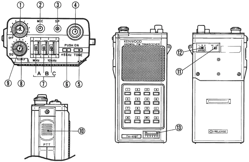
- VOL control (Volume control/power switch)
• This knob is dual-purpose; power switch and volume control.
• When this knob is turned clockwise, power is supplied.
• When this knob is further rotated, the volume level increases. - MIC jack (Microphone jack)
• Used in combination with the SP jack, for connection of the optional speaker/microphone (SMC-30) or headset with VOX (HMC-1).
Do not use other microphones other than the SMC-30 and the HMC-1, or damage to the transceiver may result. (Because DC voltage is present at the plug.)
• When the plug is inserted in this jack, the built-in microphone is automatically disconnected. - SP jack (Speaker jack)
• Connect an external speaker or earphone.
• Used with the MIC jack, for optional SMC-30 or HMC-1.
• When the plug is inserted in this jack, the built-in speaker is automatically disconnected. - Antenna connector
• Insert the supplied helical antenna and rotate to the right to secure. - Tone switch
• Activates the sub-tone (TH-41 BT/31 BT/21 BT).
• Tone unit is the optional TU-6 (TH-41 A/31 A/21 A).
• Activates 1750 Hz tone (TH-41 E/21 E). - +5 kHz switch
• When the switch is ON the operating frequency is 5 kHz higher than indicated by the thumb wheel switches. - Frequency setting switches (Thumb wheel switches)
A….. Used to be set to 1 MHz.
B……. Used to set to 100 kHz.
C……. Used to set to 10 kHz. - ON AIR indicator
• Lights for transmission.
• When this indicator lights dim, replace the batteries with new ones. - SQ control (Squelch control)
• Used to eliminate noise in non-signal conditions. For normal operation, turn the knob clockwise to the point at which noise just disappears. - PTT switch (Press-To-Talk switch)
• Press this switch and speak into the microphone for transmission.
• The microphone is built in the same place as the speaker. - Hi/Low switch
• Used to adjust the transmission output.
• At Hi position, the output power is 1 W. At the Low position, the output power is about 150 mW. - TX offset switch
Tone frequency setting switches (6P dip switches) (TH-41 BT/ 31 BT/21BT1TH-41 A/41 BT “S” Transmit and receive frequency are the same. (Also known as “Simplex”.)
“+’ Transmit frequency is 5 MHz higher than the receive frequency.
„ — Transmit frequency is 5 MHz lower than the receive frequency.TH-41 E Shifts the transmit frequency for repeater operation. Simplex (receive and transmit frequencies are the same).
“D — A” Sets the transmit frequency 7.6 MHz lower than the frequency set by the thumb wheel switches.
“D — B” Switches the transmit frequency down 1.6 MHz from the receive frequency.TH-31A/31BT Shifts the transmit frequency for repeater operation. Sii-plex (receive and transmit frequencies are the same).
“REV” Sets the receive frequency to 1.6 MHz lower than the frequency set by the thumb wheel switches.
_,. Switches the transmit frequency down 1.6 MHz from the receive frequency.TH-21A/21BT ” ” Transmit frequency is 600 kHz higher than the receive frequency.
_„ Transmit frequency is 600 kHz lower than the receive frequency.
Transmit and receive frequencies are the same. (Also known as “Simplex”.)TH-21 E Shifts the transmit frequency for repeater operation. Simplex (receive and transmit frequencies are the same).
“REV” Sets the receive frequency 600 kHz lower than the frequency set by the thumb wheel switches.
Switches the transmit frequency down 600 kHz from the receive frequency.Tone frequency setting table
Tone frequency ON…1, OFF …0
Tone frequency ON…1, OFF …0 1 2 3 4 5 6 1 2 3 4 5 6 1 67.0 0 0 0 0 0 0 21 141.3 0 1 1 1 1 1 2 71.9 0 0 0 0 1 0 22 146.2 1 0 0 0 1 0 3 74.4 0 0 0 1 0 0 23 151.4 1 0 0 0 1 1 4 77.0 0 0 0 0 1 1 24 156.7 1 0 0 1 1 0 5 79.7 0 0 1 0 0 0 25 162.2 1 0 0 1 1 1 6 82.5 0 0 0 1 1 0 26 168.9 1 0 1 0 1 0 7 85.4 0 0 1 1 0 0 27 173.8 1 0 1 0 1 1 8 88.5 0 0 0 1 1 1 28 179.9 1 0 1 1 1 0 9 91.5 0 1 0 0 0 0 29 186.2 1 0 1 1 1 1 10 94.8 0 0 1 0 1 0 30 192.8 1 1 0 0 1 0 11 100.0 0 0 1 0 1 1 31 204. 1 1 0 0 1 1 12 103.5 0 0 1 1 1 0 32 203.5 1 1 0 1 1 0 13 107.2 0 0 1 1 1 1 33 210.7 1 1 0 1 1 1 14 110.9 0 1 0 0 1 0 34 225.7 1 1 1 0 1 0 15 114.8 0 1 0 0 1 1 35 233.6 1 1 1 0 1 1 16 118.8 0 1 0 1 1 0 36 241.8 1 1 1 1 1 0 17 123.0 0 1 0 1 1 1 37 250.3 1 1 1 1 1 1 18 127.3 0 1 1 1 0 19 131.8 0 1 101 1 20 136.5 0 1 111 0
Operation
5.1. Reception
- Turn the VOL control to the right to supply power, and adjust the volume control to the desired level.
- Adjust the squelch control clockwise until the background noise just quiets.
- Adjust the frequency switches to the desired receive frequency.
5.2. Transmission
- Select the desired transmit offset.
- Check to see that the frequency is not busy.
- Press the PTT switch and speak into the microphone. The ON AIR indicator will light.
Note: The distance between the microphone and your mouth is 5 —10 cm.
5.3. DTMF key pad operation (TH-41 BT/31 BT/21 BT only)
- To operate the keyboard as a DTMF keypad press the PTT switch and dial the desired number.
- After the first number has been entered the radio will remain key for approximately 1.5 seconds, thus allowing the release of the PTT switch.
Optional accessories
The following optional accessories are available for the TH-41/31/21 series.
- Rechargeable Ni-Cd battery pack PB-21
- Heavy-Duty Ni-Cd rechargeable battery PB-21 H
- Quick battery charger BC-6
- Manganese battery case BT-2
- SUM-2 battery case (for extended operation) EB-2
- DC-DC power supply (for mobile operation) DC-21
- External speaker/microphone SMC-30
- Headset with VOX HMC-1
- Soft carrying case SC-8
- Earphone HS-8
- Antenna conversion plug (twist lock to BNC) AJ-3
- Tone unit TU-6
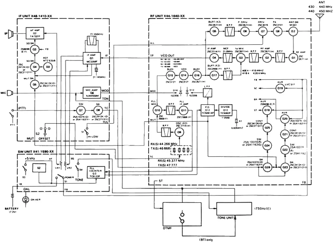
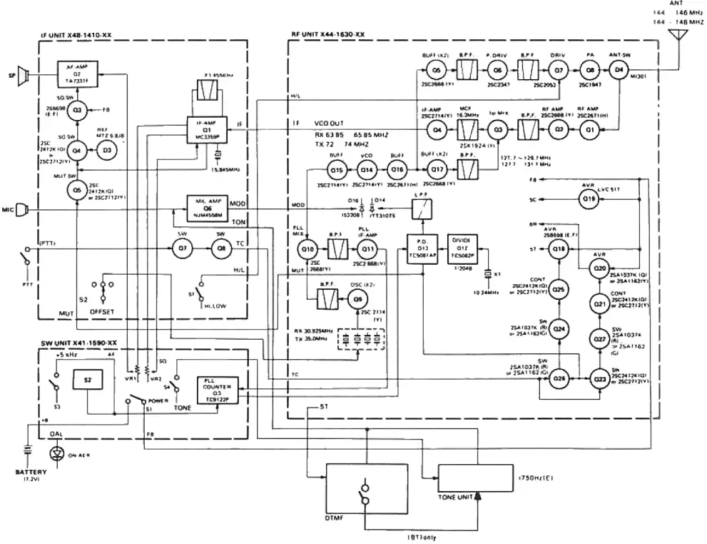
Block Diagram
- Block Diagram(TH-41 A/41 BT/41 E)

- Block Diagram(TH-31 A/31 BT)

- Block Diagram(TH-21 A/21 BT/21 E)


![]() KENWOOD CORPORATION
KENWOOD CORPORATION
Shionog: Smibuya Building, 17-5. 2-chome Shibuya, Shibuya-ku, Tokyo 150, Japan
TRIO-KENWOOD COMMUNICATIONS
Post Office Box 7065, Compton.California 90224, U.S.A
KENWOOD COMMUNICATIONS
DIVISION OF KENWOOD ELECTRONICS DEUTSCHLAND GMBH
Rembrocker Str 15, 6056 Heusenstamm, West Germany
KENWOOD ELECTRONICS BENELUX NV.
Leuvensesteenweg 504, 8-1930 Zaventem, Belgium
KENWOOD ELECTRONICS AUSTRALIA PTY. LTD.
4E Woodcock Place, Lane Cove, N.S.W. 2066. Australia


