![]()
Monitor Desk Mount
Instruction Manual
Model: HNDS7
Website: www.huanuoav.com
![]()
Thank you for choosing this HUANUO product! At HUANUO we strive to provide you with the best quality products and services in the industry. Please share your experience of our product with others at www.huanuoav.com/reviews if you are satisfied. Should you have any issues, please don’t hesitate to contact us at Technical Support: (US/CA)1-800-556-0533 Mon-Fri 8am – 8pm(PST) (USA) (CAN) (US/CA)44-808-196-3874 Mon-Fri 2pm – 10pm(UTC) Other Info: [email protected](US/CA) [email protected](DE/UK/FR/IT/ES/NL/SE/AU/PL) [email protected](JP)
IMPORTANT SAFETY INFORMATION
- Please carefully read all instructions before attempting installation. If you do not understand the instructions or have any concerns or questions, please contact our customer service at [email protected].
- CAUTION: Avoid potential personal injuries and property damage!
- Do not use this product for any purpose that is not explicitly specified in this manual. Do not exceed weight capacity. We are not liable for damage or injury caused by improper mounting, incorrect assembly or inappropriate use.
- This product contains a high pressure gas spring, fire and percussion prohibited. Also it is strictly prohibited to dismantle without professionals. Please return to the manufacturer or hand over to professional agencies if the product is abandoned.
- The desk must be capable of supporting three times the weight of the total load (the mount, the monitor and all accessories weight). Don’t use the product on particle board.
Weight Restrictions
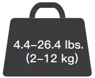
4.4-26.4 lbs. (2-12 kg)
If your monitor weighs more, this mount is NOT compatible.
![]() WARNING
WARNING
DO NOT exceed the maximum weight indicated. This mounting system is intended for use only within the maximum weights indicated. Use with products heavier than the maximum weights indicated may result in failure of the mount and its accessories, causing possible damage and or injury.
Check the VESA Pattern of Your Monitor before You Begin the Installation
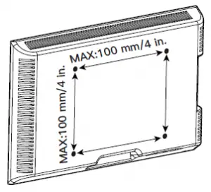
MAX:100 mm/4 in.
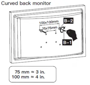
75 mm ≈ 3 in.
100 mm ≈ 4 in.
Minimum VESA pattern: 75mm/3 in.(W)x75mm/3 in.(H)
If your monitor VESA is greater than 100×100 mm/4×4 in. or less than VESA 75x75mm/3x3in., this mount is NOT compatible.
If this desk mount is NOT compatible, please contact customer service at [email protected] to find a compatible product.
Product Features

TENSION ADJUSTMENT SHOULD BE DONE ONLY AFTER MOUNT INSTALLATION
Do not adjust tension without monitor.
 Warning
- 1. Ensure monitor has been attached to the mount.
- Read your monitor box or manual to find out monitor net weight.
- Ensure the net weight of monitor (including accessories) is between
- 4~26.4 Ibs (2-12 kg).
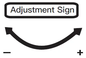
Clockwise to reduce tension(carry less weight)
Counter-clockwise to increase tension(carry more weight)
Warning!

Tools Needed (Not included)

Electric Drill (Optional)

Drill Bit (Optional) 0.4 in.(10mm) – 1.1 in.(27mm)
![]()
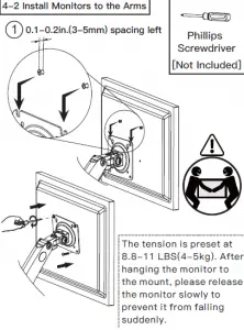
Phillips Screwdriver
Supplied Parts and Hardware for Step 1
Warning:This product contains small items that could be a choking hazard if swallowed. Before starting assembly, verify all parts are included and undamaged. Do not use damaged or defective parts. lf you require replacement parts, contact our customer service at [email protected].
- Please note: Not all hardware included in this package will be used.
Supplied Parts and Hardware for Step 1
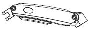
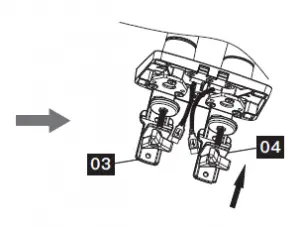
C-Clamp Part
03 X2
![]()
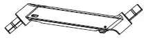
C-Clamp Part
04 X2
![]()
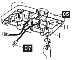
Base 05 X1
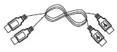
USB Line 07 X1
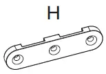
Pressure Plate x 1
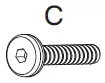
M6x12mm Bolt x 6
D

![]()
Butterfly Nut/Grommet Bolt x 1
Locking Plate x1
![]()
M4x10mm Bolt (x3)

5/32 in.(4mm) Medium Allen Key
Supplied Parts and Hardware for Step 2
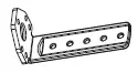
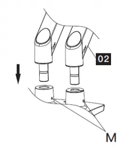
Arm 01 X2
Arm Extender 02 X2

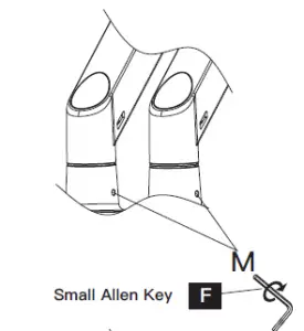
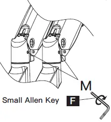
1/8 in.(3mm) Small Allen Key
Supplied Parts and Hardware for Step 3

Monitor Plate 06 X2
![]()
Bolt (x2) M8x38mm

Washer (x2)16×8.2×1.5mm 13/64 in.(5mm)
Large Allen Key
Supplied Parts and Hardware for Step 4

M4x12mm Bolt (x8)

M4x30mm Bolt (x8)

L13mm Spacer (x8)
Supplied Hardware for Step 5 and 7
![]() 13/64 in.(5mm) Large Allen Key
13/64 in.(5mm) Large Allen Key
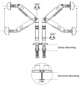
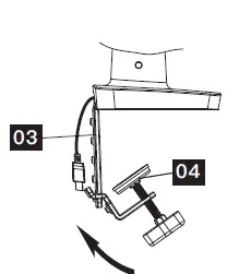
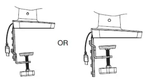
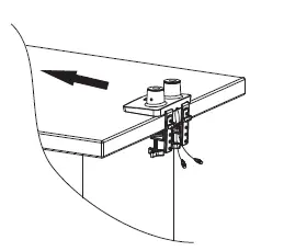
1. Install the Base A. For Clamp Mounting
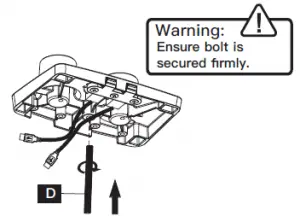
![]() Warning: Ensure bolts are secured firmly.
Warning: Ensure bolts are secured firmly.

![]()
![]()
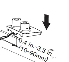
B. For Grommet Mounting
![]()
If there is no grommet hole on your desk, position the base [05] on the mounting surface and mark the hole. Drill a hole using the drill bit in a diameter of 0.4 in.(10mm) – 1.1 in.(27mm) at the marked position through the mounting surface.
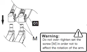
2. Install the Arms
3. Install the Monitor Plates
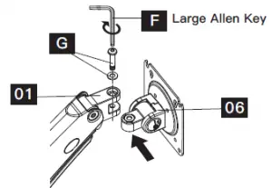
Attach the monitor plate [06] from the sides of the top end of arm [01], then secure the monitor plate using bolt and washer [G]
4. Attach Monitors to the Arms
4-1 Choose Proper Bolts Flat back monitor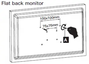
4-2 Install Monitors to the Arms
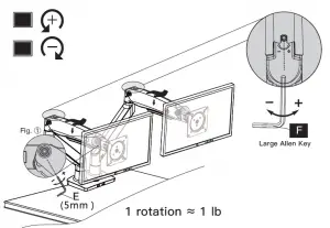
5. Adjust Gas Spring Tension
Be sure to keep the arm in horizontal position during adjustment. Or else, it would be difficult to adjust the mount or damage the mount.
- If the monitor can stay at the desired height by itself, no adjustment needed.
- If the monitor rises up, press the arm to keep it in horizontal position and then use the 13/64 in. (5mm) Alley key [F] to turn the bolts clockwise(“-” direction) to reduce tension of the arm only until the monitor can stay at the desired height by itself.
- If the monitor falls down, lift the arm to keep it in horizontal position and then use the 13/64 in. (5mm) Alley key [F] to turn the bolts counter-clockwise(“+”Be sure to keep the arm in direction) to increase tension of the arm only until the monitor can stay at the desired height by itself. horizontal position during
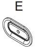
- Special situation: If the gas pressure is in mini adjustment. Or else, it would be mum torque tension and monitor is 2kg, the monitor difficult to adjust the mount or can not be hovered at your desired position freely damage the mount. and please wind the set screw(see Fig. ) in “+” direction with the wrench “E” to fix the monitor in place.
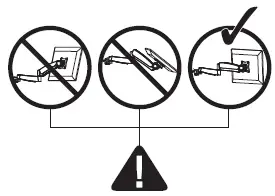
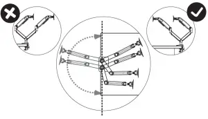
6. Rotation Restriction
Non-proper usage directions Proper usage directions
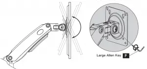
7. Tilt Adjustment
Adjust monitor to proper tilt angle, using Allen key (F) to tighten the bolt and fix tilt
angle
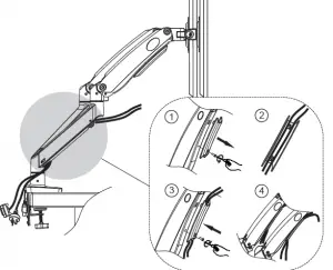
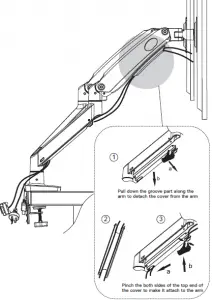
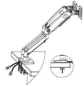
8. Route Cables along the Arms