![]() Operation and
Operation and
installation instructions
Multimedia sockets
Best.-Nr. 33 15 xx
33 15 xx Multimedia Sockets
3 x cinch/S-Video socket
Order no. 33 1532 xx
USB/3.5 mm audio socket
Order no. 33 1539 xx
VGA socket
Order no. 33 1540 xx
VGA socket with screw-in lift terminals
Order no. 33 1541 xx
High definition socket
Order no. 33 1542 xx
High definition socket with 90° plug connection
Order no. 33 1543 xx
Safety instructions
Electrical equipment must only be installed and assembled by qualified electricians.
Always follow the relevant accident prevention regulations.
Failure to comply with these instructions may result in damage to the device, fire or other hazards.
Proper signal transmission is only ensured when the appropriate accessories are used and the specified maximum cable lengths are observed, as well as the minimum permissible distance of 0.3 m from current-carrying cables and sources of interference (electronic ballasts, dimmers, ESLs, etc.) are observed.
These operating instructions are an integral component of the product, and must be retained by the end user.
Structure of the device
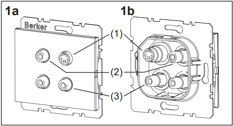
Front view (a), rear view (b) 3 x cinch/S-Video socket (Figure 1)
- S-Video jacks
- Cinch video jacks (yellow)
- Cinch audio jacks (red, white)
 USB/3.5 mm audio socket (Figure 2)
 - 3.5 mm jack sockets
- USB jacks
 VGA socket (Figure 3)
 - VGA jacks
 VGA socket with screw-in lift terminals (Figure 4)
 - VGA jacks
- Connection terminals
 High definition socket (Figure 5)
 - HDMI™ jacks
 High definition socket with 90° plug connection (Figure 6)
 - HDMI™ jacks
 USB/3.5 mm audio socket (Figure 2)
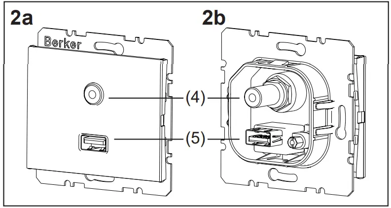 VGA socket (Figure 3)
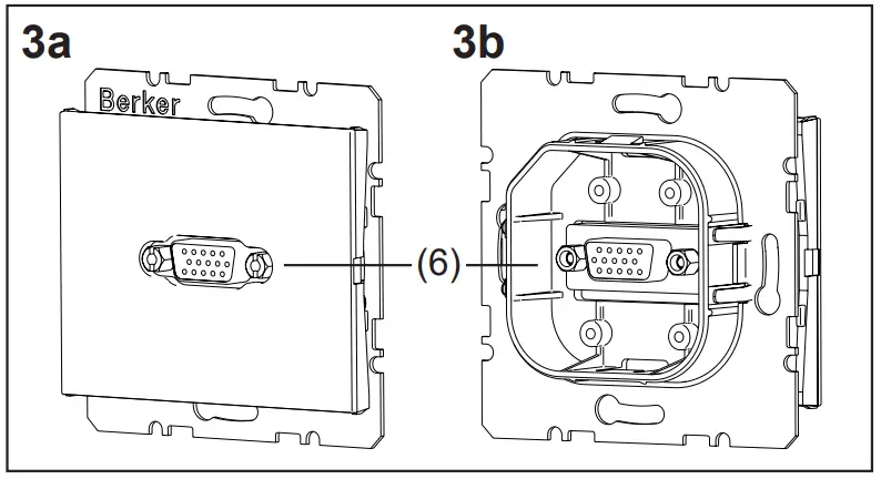 VGA socket with screw-in lift terminals (Figure 4)
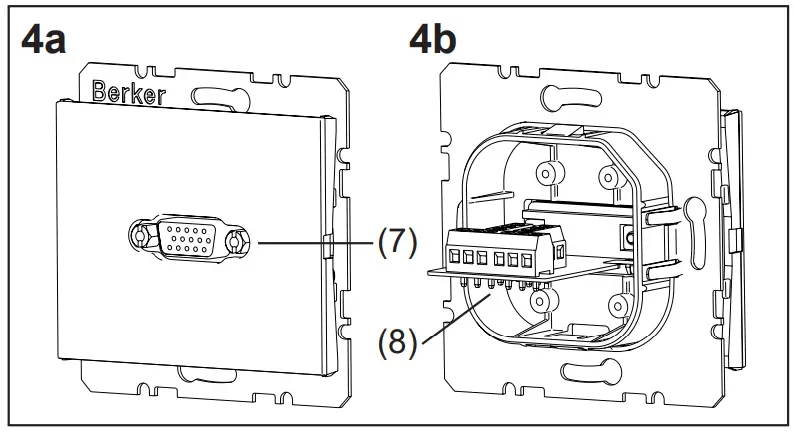 High definition socket (Figure 5)
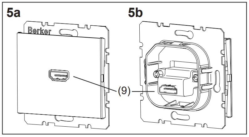 High definition socket with 90° plug connection (Figure 6)
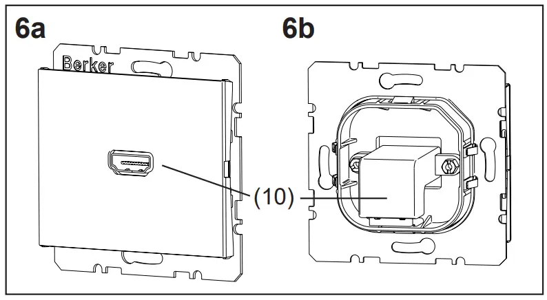
Function
The multimedia sockets serve to connect input and output devices for transmission of audio/video signals and data.![]() The available functions depend on the devices that are connected. To select the suitable socket, note the information from the manufacturer of the connected devices.
The available functions depend on the devices that are connected. To select the suitable socket, note the information from the manufacturer of the connected devices.
Intended use
– Only suitable for use in indoor areas
– Can be used in multiple combinations
– Flush-mounting in wall box according to DIN VDE 0606
– Connection of audio/video devices via „Plug&Play“
Operation
![]() CAUTION!
CAUTION!
The use of non-standardised connecting cables and connectors can cause device malfunctions.
The devices may be destroyed.
Use only approved connecting cables and connectors.
Connecting multimedia devices
- Insert connector of the connecting cable from the signal source, e.g. from a DVD or MP3 player, into the jack of the multimedia socket.
- Insert connector of the connecting cable from a playback device, e.g. from an LCD/plasma tele vision or stereo system, into the jack of a second multimedia socket.
 Insert connectors into the jacks straight and without using force. Twisting or tilting the connector may deform the contacts.
Application examples
| Connection | Devices |
| Cinch | Audio systems, AV receivers, active loudspeakers .. |
| S-Video | SAT receivers, televisions, projectors, iPod docking stations, video cameras .. |
| USB | iPods, printers, storage media, digital cameras .. |
| 3,5 mm au- dio | MP3 players, CD/DVD players, sound cards, audio systems .. |
| VGA | PCs/laptops, projectors, monitors .. |
| High definition | High definition plasma/LCD televisions, SAT receivers, projectors, game consoles, DVD/Blu-ray players, DVD/HDD recorders, video cameras .. |
Information for electricians
Assembly
Connecting and installing the multimedia socket The connecting cable has been laid, the wall box is installed in the wall.![]() Recommendation: use Kaiser “Electronics Box” (Art. no. 1068-02 or 9062-74) in order to maintain the permissible bending radii.
Recommendation: use Kaiser “Electronics Box” (Art. no. 1068-02 or 9062-74) in order to maintain the permissible bending radii.
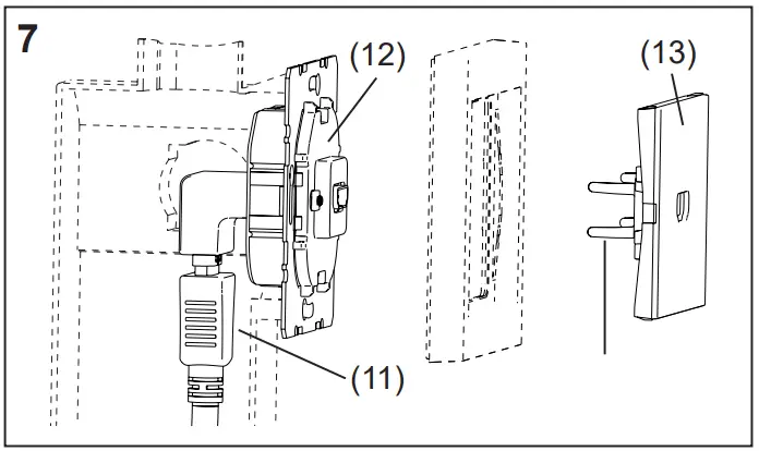
- Insert connector of the connecting cable into the corresponding jack on the rear of the multimedia socket (Figure 7, 11) or
- When using the VGA socket with screw-in lift terminals, prepare the wire ends and connect to the terminals according to the terminal assignment (Figure 8, Table 1).
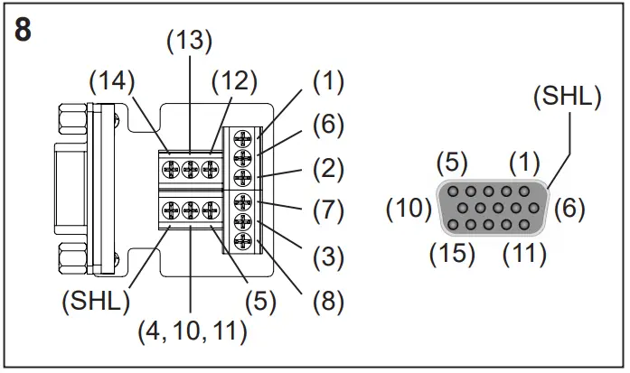
| PIN/ Terminal | Transmission signal | Wire |
| 1 | red | Coaxial wire |
| 2 | green | Coaxial wire |
| 3 | blue | Coaxial wire |
| Monitor ID bit 2 | Twisted pair wire (optional connection) | |
| 5 | Ground | Twisted pair wire |
| 6 | red ground | Coaxial shielding |
| 7 | green ground | Coaxial shielding |
| 8 | blue ground | Coaxial shielding |
| 9 | — | — |
| 10* | Synchronous ground | Twisted pair wire |
| 11* | Monitor ID bit 0 or digital ground | Twisted pair wire (optional connection) |
| 12 | Monitor ID bit 1 | Twisted pair wire (optional connection) |
| 13 | Horizontal synchronisation | wire 1 |
| 14 | Vertical synchronisation | wire 2 |
| 15 | Monitor ID bit 3 | – |
| SHL | Housing shielding | External shielding |
* Are connected together at one terminal
Table 1: Contact pinouts of the VGA socket with screw-in lift terminals
- Screw insert (Figure 7, 12) to the wall box in the right orientation via the supporting ring.
- Place centre plate (Figure 7, 13) into the frame.
- Mount centre plate together with the frame on the insert using clamp springs (Figure 7, 14).
The multimedia wall box can be commissioned.
Commissioning
![]() CAUTION!
CAUTION!
Short-circuit if devices that are switched on are connected.
Devices may be destroyed.
Switch all devices off before connecting them.
Carrying out a functional test
Multimedia devices are connected.
- Activate the desired functions and check the signal transmission at the signal sources and the playback device, e.g. play a DVD and check picture/sound reproduction on a television set.
The multimedia socket is ready for operation.
Appendix
Technical data
| Ambient temperature: | -5 to +45 °C |
| Cinch jacks | |
| Rated voltage Frequency ranges | DC 50 V= |
| – Audio | 20 Hz to 20 KHz |
| – Video | ≤ 160 MHz |
| Contact resistance | ≤ 20 mΩ |
| Insulation resistance | ≥ 100 mΩ |
| Electric strength | AC 500 V~ (50/60 Hz) for 1 min 2 mA |
| Insertion and removal forces | 3 N to 25 N |
| – Cycles Connection | 1000 insertion/removal operations |
| – Double jacks | yellow (video) white (audio, left) red (audio, right) |
| – Contact material | gold-plated |
| S-Video jacks | |
| Rated voltage Frequency range | DC 50 V= |
| – Video | ≤ 160 MHz |
| Contact resistance | ≤ 80 mΩ |
| Insulation resistance | ≥ 50 mΩ |
| Electric strength | AC 500 V~ (50/60 Hz) for 1 min 2 mA |
| Insertion forces | ≤ 44.1 N |
| Removal forces | 5.88 N to 29.4 N |
| – Cycles Connection | 1000 insertion/removal operations |
| – Double jack | S-Video |
| – Contact material | gold-plated |
| USB jacks | |
| Standard | USB 3.0 |
| Date rate Connection | max. 5 Gbit/s |
| – Double jack | Type A, 180° |
| 3.5 mm audio jacks | |
| Rated voltage Frequency range | DC 50 V= |
| – Audio | 20 Hz to 20 KHz |
| Contact resistance | ≤ 20 mΩ |
| Insulation resistance | ≥ 100 mΩ |
| Electric strength | AC 500 V~ to 2000 V~ DC 800 V= |
| Insertion and removal forces | 4.9 N to 14.7 N |
| – Cycles Connection | 2000 insertion/removal operations |
| – Double jack | 3.5 mm Audio “Stereo”, 180° |
| – Contact material | gold-plated |
| HDMI™ jacks | |
| Standard | 1.3/Category 2 Support for HDMI™ technology (V 1.3 with Deep Color) |
| Resolution | ≤ 1080p (1920 x 1080 pixels) |
| Vertical frequency range | 50 to 85 Hz |
| Date rate Connection | max. 8.16 Gbit/s |
| – Double jack | HDMI™ type A, 180°/90° |
| – Contact material | gold-plated |
| VGA jacks | |
| Resolution | ≥ 800 x 600 pixels ≤ 1280 x 1024 pixels S-VGA compatible |
| Frequency range | |
| – Video | ≤ 160 MHz |
| Contact resistance | ≤ 30 mΩ |
| Insulation resistance | ≥ 1000 mΩ |
| Electric strength | AC 1000 V~ (50 / 60 Hz) for 1 min 2 mA |
| Insertion forces | 43.9 N |
| Removal forces | 3.92 N |
| – Cycles | 500 insertion/removal operations |
| Connection | |
| – Jack | 15pole D-subminiature, 180° |
| – Conductor cross-section | Screw-in lift terminal ≤ 1.5 mm2 |
Troubleshooting
No signal at the playback device after the signal sources is switched on.
Cause 1: Playback device is not switched on.
- Switch on playback device.
Cause 2: Loose connector. - Check that all connections are properly seated.
No video signal at the playback device after the signal sources is switched on.
Cause 1: Signal source is not recognised by the playback device.
- Manual selection of the signal source using remote control or channel selection buttons of the player.
Cause 2: VGA output of the signal source is not activated. - Activate VGA output. Note information of the device manufacturer.
No audio signal at the playback device after the signal sources is switched on.
Cause 1: Volume control on the signal source or on the playback device is set too low.
- Increase volume.
Cause 2: The audio on the playback device is set to mute. - Deactivate the mute function. Note information of the device manufacturer.
Warranty
We reserve the right to make technical and formal changes to the product in the interest of technical progress.
Our products are under guarantee within the scope of the statutory provisions.
If you have a warranty claim, please contact the point of sale or ship the device postage free with a description of the fault to the appropriate regional representative.
![]() Berker GmbH & Co. KG
Berker GmbH & Co. KG
Zum Gunterstal
66440 Blieskastel/Germany
Tel.: + 49 6842 945 0
Fax: + 49 6842 945 4625
E-Mail: [email protected]
www.berker.com


