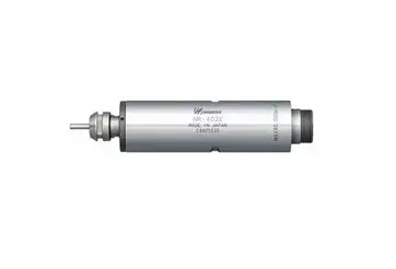
NAKANISHI NR-3060S Straight Spindle
Thank you for purchasing spindle NR-3060S. This spindle designed for grinding, small diameter drilling and milling, etc. The E3000 <Control Unit>, <Blushless Motor>, <Air Line Kit (AL-0201)> or <Air Motor> , <Air Line Kit (AL-0304 or AL-951)> are rquired to drive this spindle. Read this and all the associated component Operation Manuals carefully before use. Always keep this Operation Manual in a place where a user can referred to for reference at any time.
CAUTIONS FOR HANDLING AND OPERATION
- Read these warnings and cautions carefully and only use in the manner intended.
- These warnings and cautions are intended to avoid potential hazards that could result in personal injury or damage to the device. These are classified as follows in accordance with the seriousness of the risk.
| Class | Degree of Risk |
| A safety hazard could result in bodily injury or damage to the device if the safety instructions are not properly followed. |
| A hazard that could result in light or moderate bodily injury or damage to the device if the safety instructions are not followed. |
① The spindle is not a hand tool. It is designed to be used on CNC machines or special purpose machines. |
① Do not drop or hit the spindle, as shock can damage to the internal components. |
BASIC PACKAGE
When opening the package, check if it includes all items listed in ” Table. 1 Packing List Contents “. In the event of any shortage, please contact either NAKANISHI (see the ” 4. CONTACT US ” section) or your local dealer.
|
| 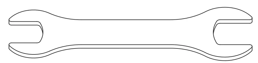 Wrench (12 × 14)・・2pcs. |
|
|
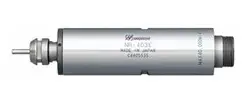
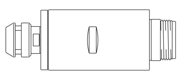 Spindle・・1pc
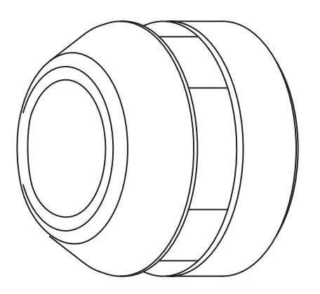 Collet Nut (K-265)・・1pc.*
 Operation Manual・・1set.
 Inspection Card・・1pc.
Table. 1 Packing List Contents
WARRANTY
We provide a limited warranty for our products. We will repair or replace the products if the cause of failure is due to the following manufactures defects. Please contact us or your local distributor for details.
(1) Defect in manufacturing.
(2) Any shortage of components in the package.
(3) Where damaged components are found when initially opening the package.
(This shall not apply if the damage was caused by the negligence of a customer.)
CONTACT US
For your safety and convenience when purchasing our products, we welcome your questions. If you have any questions about operation, maintenance and repair of the product, please contact us.
Contact Us
- For U.S. Market
Company Name
Business Hours
U.S. Toll Free No. Telephone No. Fax No. Website
: Industrial Div.
: 8:00 to 17:00 (CST) (closed Saturday, Sunday and Public Holidays)
: +1 800 585 4675
: +1 847 843 7664
: +1 847 843 7622 : www.nskamericacorp.com
For Other Markets Company Name Business Hours
Telephone No. e-mail
: : 8:00 to 17:00 (JST)
(closed Saturday, Sunday and Public Holidays) : +81 289 64 3520
: [email protected]
FEATURES
The spindle housing is made from precision ground, hardened, stainless steel (SUS) with an outside diameter of 30mm.
The spindle utilizes ceramic bearing for 60,000min-1. Various sizes of collets are available CHK 0.5mm – 6.35mm. Standard collet is CHK 3.0mm or CHK
3.175mm. (For U.S. market CHK 3.175mm.)
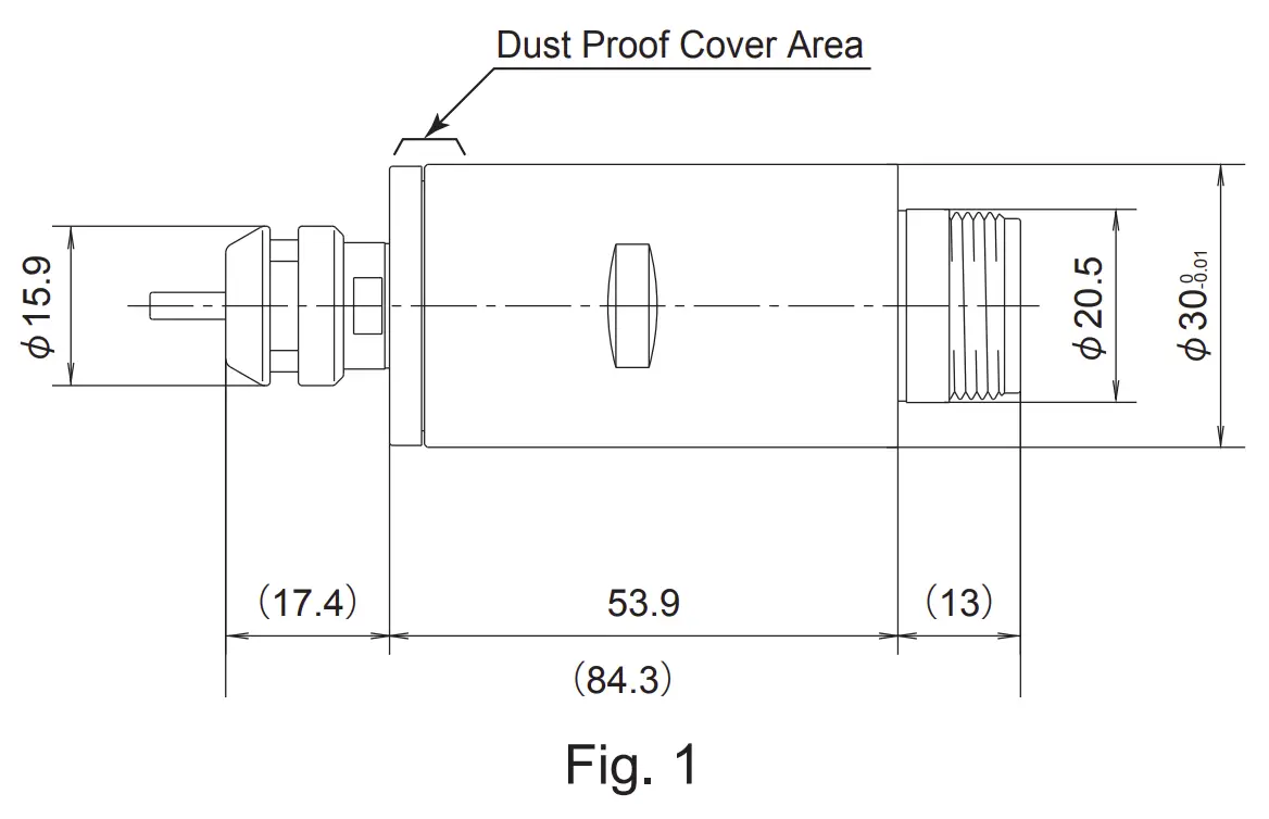
SPECIFICATIONS AND DIMENSIONS
Specifications
| Model | NR-3060S | ||
| Allowable Motor Speed | 60,000min-1 (Continuous use : Less than 50,000min-1) | ||
| Spindle Accuracy | Within 1µm | ||
| Weight | 260g | ||
| Temperature | Humidity | Atmospheric Pressure | |
| Operation Environment | 0 – 40°C | MAX.75% (No condensation) | 800 – 1,060hPa |
| Transportation and Storage Environment | -10 – 50°C | 10 – 85% | 500 – 1,060hPa |
Outside View
< Option >
| Collet (CHK- □□ )*Note 1 | φ0.5mm~φ6.0mm in 0.1mm increments andφ2.35mm, φ3.175mm, φ6.35mm |
| Collet Nut | K-265 |
*Note 1 : Collet is sold separately. Please select the suitable collet size for your application.
Make sure your hands and all interlocking parts of the spindle and motor are clean before connecting the motor to the spindle. This is critical to prevent contaminants from entering the motor or spindle. |
Align the threads on the front end of the motor and the rear end of the spindle, and turn the spindle clockwise If the drive shaft of the motor does not engage the drive dog on the spindle, the spindle could not be turned. DO NOT FORCE. Turn the spindle back a few threads, rotate the cutting tool by hand to engage the drive shaft and the drive dog, and make the final turns with provided 27mm wrench. (Fig. 2)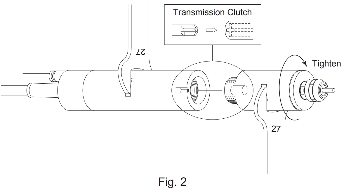
CHANGING THE TOOL
Do not tighten the collet without inserting a tool or dummy bur, as this will damage the collet, spindle or collet nut, causing difficulty removing the collet. |
RECOMMENDATION Please set the cutting tools to minimize the overhang amount. 13mm is the maximum amount of overhang to maintain high accuracy and safety |
① Set the provided 12mm wrench on the spindle.
② Place the provided 14mm wrench on the collet nut and turn it counterclockwise to loosen the collet and remove the tool. (The first turn will loosen the collet nut, but the tool will not release and turning will become stiff. Keep turning through the stiffness and the collet will open.)
③ Clean the collet and collet nut, then insert the new tool and tighten the collet by turning clockwise. Do not over tighten.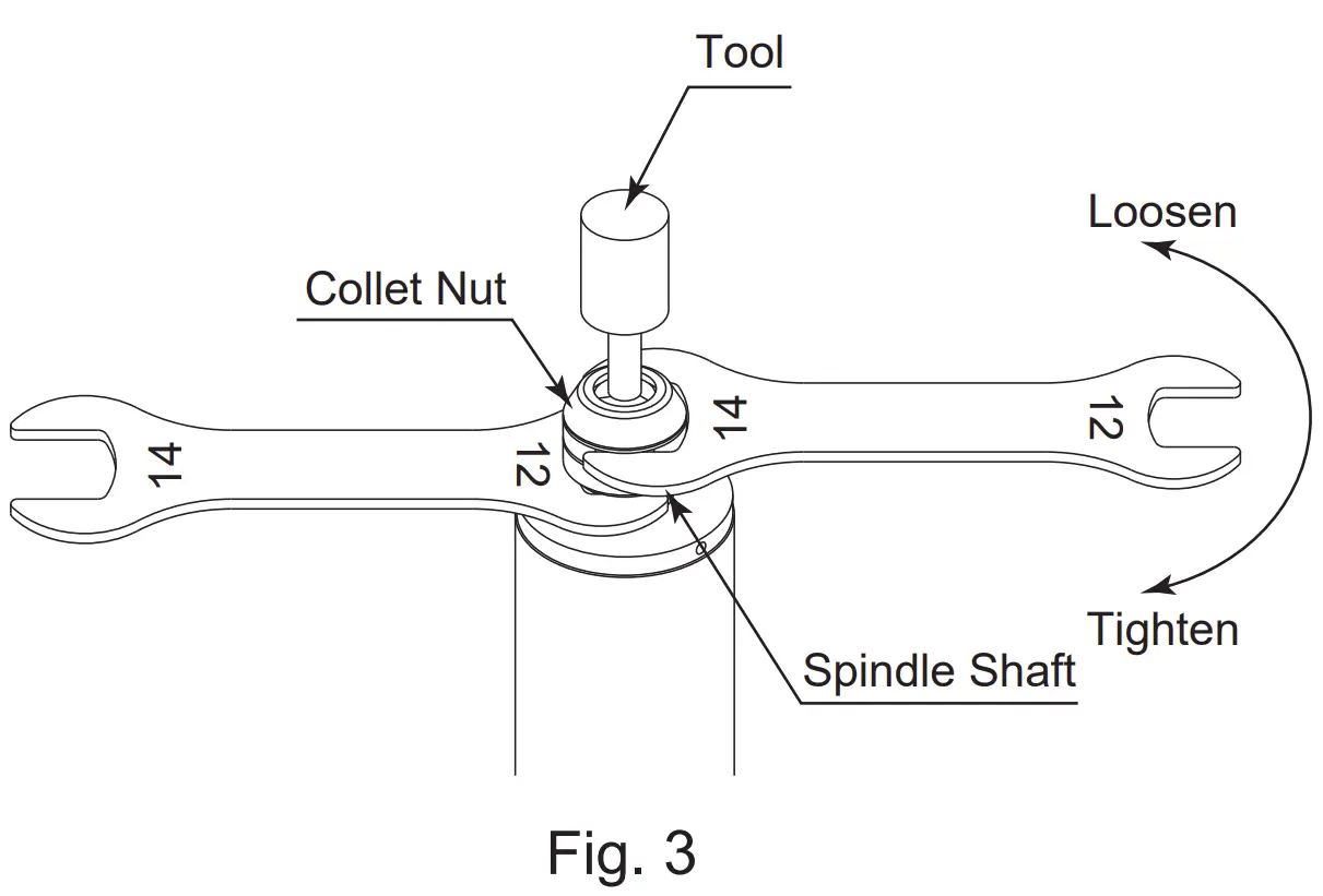
REPLACING THE COLLET
① Remove the tool according to the section 8. ” CHANGING THE TOOL ” procedure above and remove collet nut assembly. (Fig. 4)
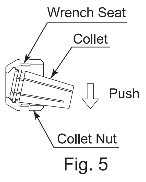
② The collet and collet nut are secured by a groove in the collet and a flange in the collet nut. To remove the collet hold the collet nut in one hand and push diagonally down on the collet. The collet should be released.(Fig. 5)
③ Install the new collet in the collet nut by positioning the collet in the collet nut and pressing down on a flat surface. (Fig. 5)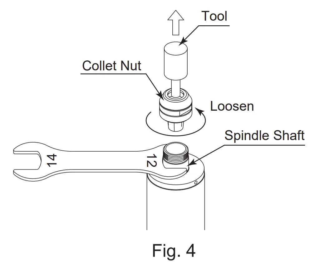
INSTALLATION OF THE SPINDLE
In case of using the electric motor, when installing a spindle to a fixed base, make sure the fixed base is grounded in order to avoid the risk of an electric shock. |
|
① When mounting a spindle, refer to the Clamping Area etched on the spindle. (Fig. 6)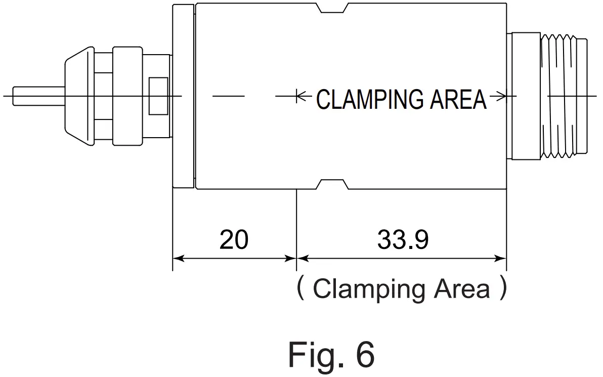
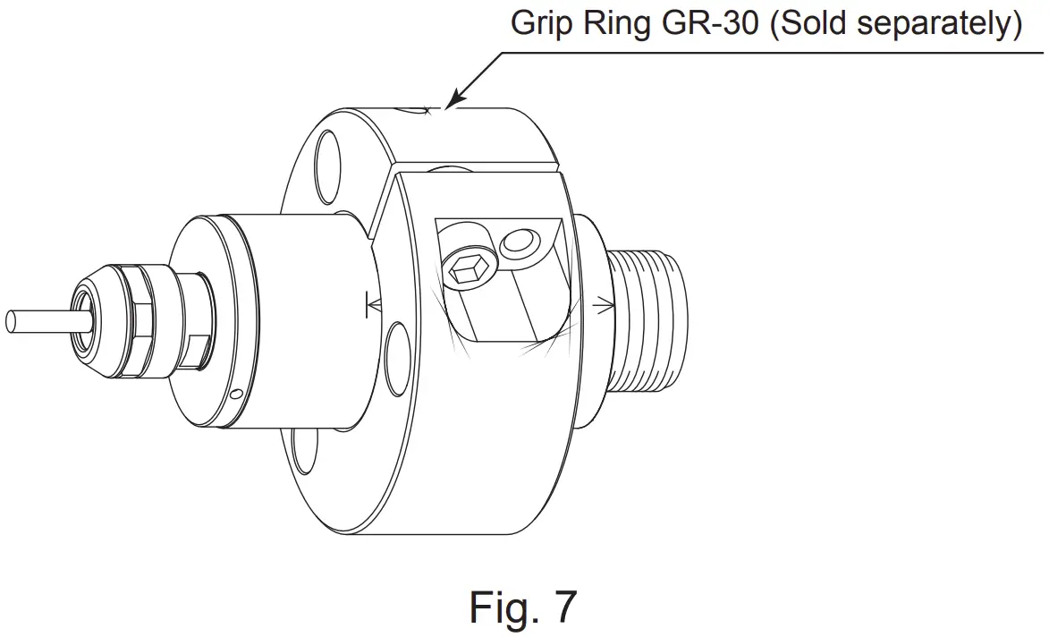
※ When installing a spindle, use a ” Grip Ring GR-30 (sold separately) ” recommended.
If the Grip Ring GR-30 (sold separately) cannot be used due to the restriction of dimension and space, install as shown in ② below
② When installing a spindle to the holder, recommended installation method is shown Fig 8. Refer to ” ③ How to fabricate the Split Type Holder. If this is not possible, install as shown in Fig. 9.
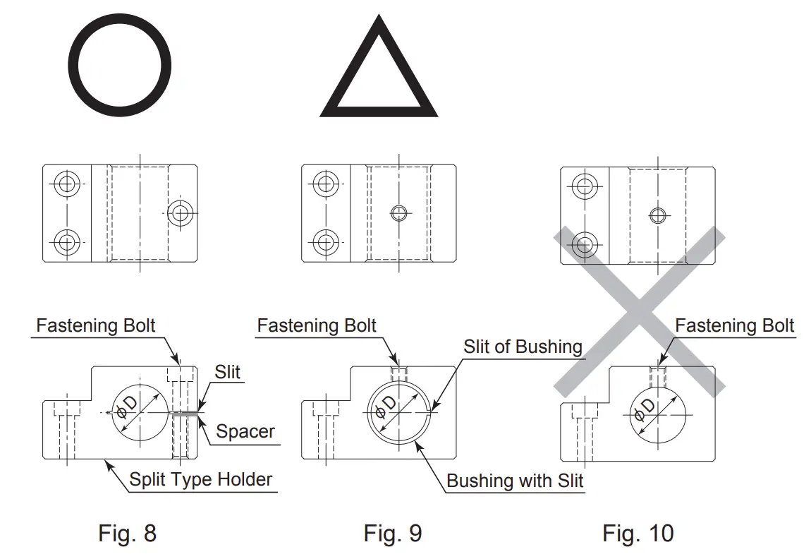
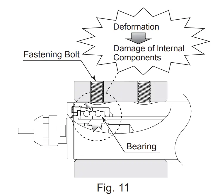
Do not allow set screws to come directly in contact with the spindle body as shown in Fig. 10, as this will result in damage to the spindle housing and internal components. When installing, never clamp directly over the bearings, as this will result in bearing damage. (Refer to Fig. 11) |
③ How to fabricate the Split Type Holder
(1) Roughly process (carve) the inside diameter of the Split Type Holder.
(2) Cut a slit. (Ex. Slit 2mm)
(3) Twist the Screw for Removal and Broaden the Slit Area.
(4) Insert spacer (ex t = 2mm) into the SlitArea.
(5) Loosen the Screw for Removal, and tighten the fastening bolt with the specified torque.
(6) Finish the Split Type Holder so that the inside diameter of the Split Type Holder is φ30 with its tolerans range from – 0.01mm to – 0.015mm, and its roundness and cylindricity of less than 5µm.
(7) When inserting the spindle loosen the Fastening Bolt and twist the Screw for Removal, and broaden the Slit Area.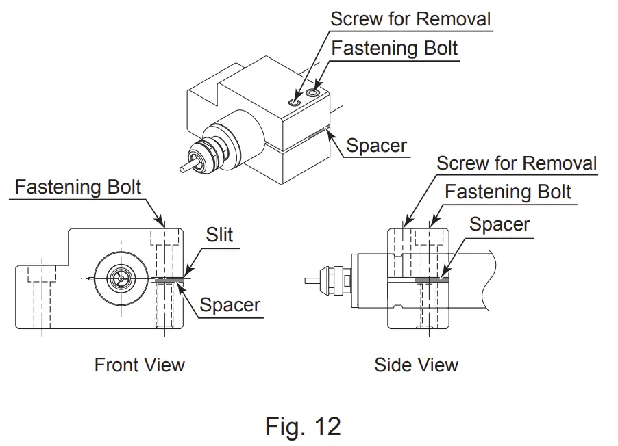
|
BREAK-IN PROCEDURE
During transportation, storage or installation the grease inside the bearings will settle. If the spindle is suddenly run at high-speed excessive heat will cause bearing damage.
After installation, repair, initial operation, or long periods of non operation please follow the break-in procedure detailed in Table 1.
Table 1.
| Steps | 1 | 2 | 3 | 4 | 5 |
| Rotation Speed (min-1) | 15,000 | 30,000 | 40,000 | 50,000 | 60,000 |
| Rotation Time (min) | 15 | 10 | 10 | 10 | 10 |
| Items to Check | No Abnormal Noises | Spindle Housing no hotter than 20°C. If hotter than 20°C stop for at least 20 minutes, check installation and restart Break- In procedure. | Spindle Housing less than 20°C. | ||
CAUTIONS IN USING GRINDSTONES AND CUTTING TOOLS
The maximum surface speed or rpm is always specified for a grindstone. Do not exceed the maximum speed with reference to the calculating chart below. Always follow the grindstone manufacturers recommendations.
|

① The proper surface speed for general grindstones is 10 – 30 m /s.
② Do not exceed 13mm of overhang for mounted grindstones as shown in Fig. 13. If the overhang must exceed 13mm, reduce the motor speed in accordance with Table 2.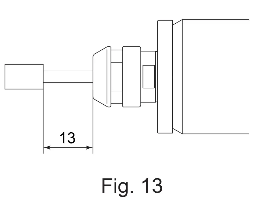
③ Dress the grindstone prior to use.
④ Do not use cutting tools with bent or broken shanks, cracks or excessive run – out.
⑤ For grinding, the maximum depth of cut should not exceed 0.01mm radially or axially. Reciprocate the tool several times after each pass to eliminate tool pressure.
⑥ Always operate tools within the allowable recommended speed of the tools. Use of a tool outside of the allowable speed of the tools could cause damage to the spindle and injury to the operator.
⑦ Keep the tool shank and collet clean. If contaminants are left in the collet or collet nut, excessive run-out will cause damage to the tool and or spindle.
⑧ Do not strike or disassemble the spindle.
⑨ Please set the tools to minimize the overhang amount. 13mm is the maximum amount of overhang to maintain high accuracy and safety.
Table 2. Overhang and Speed
| Overhang (mm) | Max. Speed (min-1) |
| 20 | N x 0.5 |
| 25 | N x 0.3 |
| 50 | N x 0.1 |
※ N=Max. Operating Speed with 13mm overhang.
TROUBLESHOOTING
If a problem or concern occurs, please check the following prior to consulting your dealer.
| Trouble | Cause | Inspection / Corrective Action |
| Spindle does not run. | The ball bearings are damaged. | Replace the ball bearings. (Return to NAKANISHI dealer service.) |
| Motor is broken. | Replace the motor. (Return to NAKANISHI dealer service.) | |
| Overheating during rotation. | Cutting debris has contaminated the ball bearing, and the ball bearings are damaged. | Replace the ball bearings. (Return to NAKANISHI dealer service.) |
| Abnormal vibration or noise during rotation. | Using bent tool. | Replace the cutting tool. |
| Cutting debris has contaminated the ball bearings. | Replace the ball bearings. (Return to NAKANISHI dealer service.) | |
| The ball bearings are worn. | ||
| Tool slippage. | Collet or collet nut are not correctly installed. | Check and clean the collet and collet nut. And, tighten the collet accurately again. |
| The collet and the collet nut are worn. | Replace the collet and the collet nut. | |
| High run-out. | The cutting tool is bent. | Change the cutting tool. |
| Collet nut is not correctly installed. | Secure the collet and the collet nut correctly. | |
| The collet and the collet nut are worn. | Replace the collet and the collet nut. | |
| Inside of the spindle is worn. | Replace the spindle shaft. (Return to NAKANISHI dealer service.) | |
| Contaminants inside the collet and the collet nut or the spindle. | Clean the collet, collet nut and the inside of the spindle. | |
| The ball bearings are worn. | Replace the ball bearings. (Return to NAKANISHI dealer service.) |
DISPOSAL OF THE SPINDLE
When disposal of a spindle is necessary, follow the instructions from your local government agency for proper disposal of industrial components.
NAKANISHI INC ![]()
700 Shimohinata, Kanuma
Tochigi 322-8666
Japan
www.nakanish-inc.com
NSK America Corp.
1800 Global Parkway
Hoffman Estates
IL60192, USA
www.nskamericacorp.com
NSK Europe GmbH ![]()
Elly-Beinhorn-Strasse 8
65760 Eschborn
Germany
NSK United Kingdom Ltd.
UK Authorised Representative
Office 4, Gateway 1000
Arlington Business Park, Whittle Way
Stevenage, SG1 2FP, UK
Contents are subject to change without notice.