![]() OM-K0994MA000 iSpeed3 Motor Spindle
OM-K0994MA000 iSpeed3 Motor Spindle
Instruction Manual
OM-K0994MA000 iSpeed3 Motor Spindle
Thank you for purchasing iSpeed3 Motor Spindle. This motor spindle designed for grinding, small diameter drilling and milling, etc.
An iSpeed3 CONTROLLER and AL-0201 Air Line Kit are required to drive this motor spindle. Read this Operation Manual carefully before using. Also read the iSpeed3 CONTROLLER and Air Line Kit (AL-C1204) Operation Manuals. Always keep this Operation Manual in a place where a user can referred to for reference at any time.
CAUTIONS FOR HANDLING AND OPERATION
■ Read these warnings and cautions carefully and only use in the manner intended.
■ These warnings and cautions are intended to avoid potential hazards that could result in personal injury or damage to the device.
These are classified as follows in accordance with the seriousness of the risk.
| Class | Degree of Risk |
| A safety hazard could result in bodily injury or damage to the device if the safety instructions are not properly followed. | |
| A hazard that could result in light or moderate bodily injury or damage to the device if the safety instructions are not followed. |
![]() WARNING
WARNING
- This motor spindle is not a hand tool. It is designed to be used on CNC machines or special purpose machines.
- Do not touch the cutting tool while it is running. It is very dangerous.
- Wear safety glasses, dust mask and use a protective cover around the motor spindle whenever the motor spindle is rotating.
- Never connect, disconnect or touch the Power Cord Plug and Motor Cord Plug with wet hands. This may cause an electric shock.
- Never operate or handle the motor spindle until you have thoroughly read the owner’s manual and safe operation has been confirmed.
1) To prevent injuries / damages, check the motor spindle and cutting tool for proper installation, before operating the motor spindle.
2) Before disconnecting the motor spindle, always turn the control power off and turn the compressed air supply to the CONTROLLER off. Then it is safe to remove the motor spindle. - When installing a tool, tighten the collet correctly and check again the collet and collet nut before use. Do not overtighten the collet. This may cause damage to the spindle.
- Do not use bent, broken, chipped, out of round or sub-standard tools as they may cause shatter or explode. Tool with fractures or a bent shank will cause injury to the operator. When using a new tool, rotate it in a low speed and increase speed gradually for safety.
 WARNING
 - Do not exceed the maximum recommended allowable tool speed. For your safety, use speeds below the maximum allowable speed.
- Do not apply excessive force. This may cause tool slippage, tool damage, injury to the operator or loss of concentricity and precision.
![]() CAUTION
CAUTION
- Do not drop or hit this motor spindle, as shock can damage to the internal components.
- Be sure to clean the collet and collet nut, the inside of the spindle before replacing the tool. If ground particles or metal chips stick to the inside of spindle or the collet, damage to the collet or spindle can occur due to the loss of precision.
- When cleaning a motor spindle, stop the motor spindle and remove debris with a soft brush or a cloth. Do not blow air into the dust proof cover area (refer to section 6 – 2 ” Outside view “) with compressed air as foreign particles or cutting debris may get into the ball bearing.
- Always clean the tool shank before installing the tool in the spindle.
- When sizing the correct collet size to the tool shank diameter, a tolerance of + 0 ~ – 0.01mm is strongly recommended. A tool shank within the + 0 ~ – 0.1mm range is mountable, however, this may cause poor concentricity and or insufficient tool shank gripping force.
- Select suitable products for all applications. Do not exceed the capabilities of the motor spindle or tools.
- Carefully direct coolant spray to the tool. Do not spray directly on the motor spindle body.
- Stop working immediately when abnormal rotation or unusual vibration are observed. Afterwards, please check the content of section 13. ” TROUBLESHOOTING “.
- Always check if the tool, collet or collet nut are damaged before and after operating.
- If the collet or collet nut show signs of wear or damage, replace them before a malfunction or additional damage occurs.
- After installation, repair, initial operation, or long periods of non operation, please refer to section 11. ” BREAKIN PROCEDURE ” detailed in Table 4. When checking the motor spindle, no vibration or unusual sound should be observed during rotation.
- Do not disassemble, modify or attempt to repair this motor spindle. Additional damage will occur to the internal components. Service must be performed by NSK NAKANISHI or an authorized service center.
- When using this motor spindle for mass production, please purchase the another motor spindle as a spare in case of an emergency.
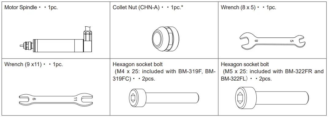
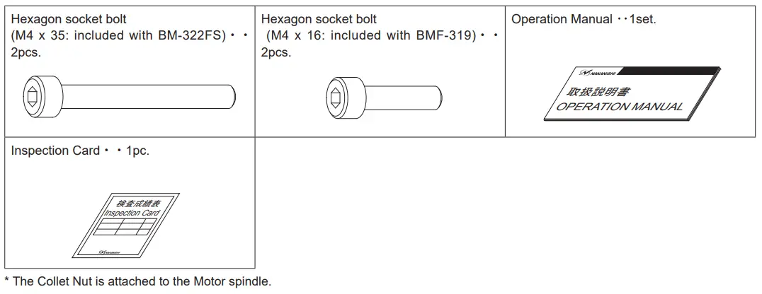
BASIC PACKAGE
When opening the package, check if it includes all items listed in ” Table. 1 Packing List Contents “.
In the event of any shortage, please contact either NAKANISHI (see the ” 4. CONTACT US ” section) or your local dealer.
Table. 1 Packing List Contents
WARRANTY
We provide a limited warranty for our products. We will repair or replace the products if the cause of failure is due to the following manufactures defects. Please contact us or your local distributor for details.
- Defect in manufacturing.
- Any shortage of components in the package.
- Where damaged components are found when initially opening the package.
(This shall not apply if the damage was caused by the negligence of a customer.)
CONTACT US
For your safety and convenience when purchasing our products, we welcome your questions.
If you have any questions about operation, maintenance and repair of the product, please contact us.![]() Contact Us
Contact Us
| For U.S. Market Company Name Business Hours U.S. Toll Free No. Telephone No. Fax No. Website | :NSK America Corp Industrial Div. : 8:00 to 17:00 (CST) (closed Saturday, Sunday and Public Holidays) : +1 800 585 4675 : +1 847 843 7664 : +1 847 843 7622 : www.nskamericacorp.com |
| For Other Markets Company Name Business Hours Telephone No. | :NAKANISHI INC. : 8:00 to 17:00 (JST) (closed Saturday, Sunday and Public Holidays) : +81 289 64 3520 : [email protected] |
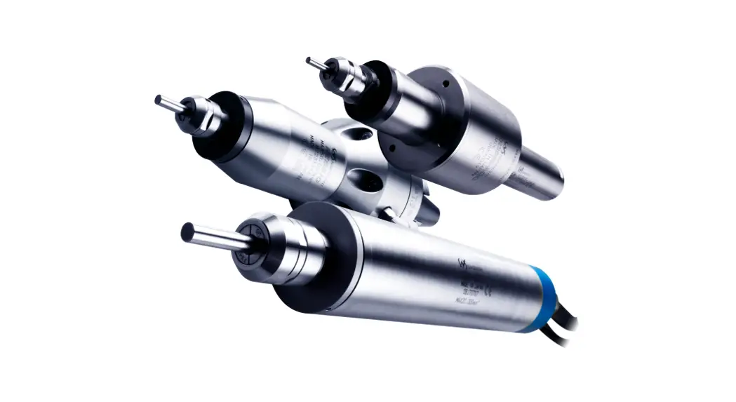
FEATURES
- The motor spindle housing is made from precision ground, hardened, stainless steel (SUS) with outside mounting diameters of φ 19.05 mm, φ20 mm, φ22mm. Provides several different configurations for various machine types.
- Excellent durability and high reliability are obtained by using a high-speed brushless motor, which eliminates the need for brush replacement and frequent maintenance.
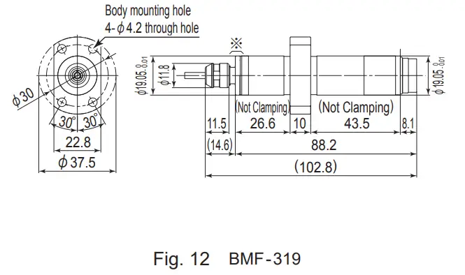
- Two new models have been lined up; Motor Spindle with Quick Disconnect Cord (BM-319 / BM-319F / BM-319FC / BM-320 / BM-320F / BM-322 / BM-322FR / BM- 322FL / BM-322FS) and Motor Spindle with End Face Connector (BMJ- 319 / BMF- 319 / BMJ- 320 / BMJ – 322).
SPECIFICATIONS AND DIMENSIONS
6 – 1 Specifications
- BM-319 / BM-319F / BM-319FC / BM-320 / BM-320F / BM-322 / BM-322FR / BM-322FL / BM-322FS
Model BM- 319 BM-319F BM-319FC BM- 320 BM-320F BM- 322 BM-322FR BM-322FL BM-322FS Max. Motor Speed 80,000min-1 60,000min-1 Spindle Accuracy Within 1μm Max. Output 140W 150W Motor Cord Type (Opution) EMCD- BM3 – 3M (3m) / EMCD- BM3 – 5M (5m) / EMCD- BM3 – 7M (7m) Quick Disconnect Cord Length 0.5m 0.5m 1m 0.5m Weight 210g 260g 290g 230g 270g 250g 360g 360g 430g Noise Level Within 70dB IP Code IP 57 - BMJ-319 / BMF-319 / BMJ-320 / BMJ-322
Model BMJ- 319 BMF- 319 BMJ- 320 BMJ- 322 Max. Motor Speed 80,000min-1 60,000min-1 Spindle Accuracy Within 1μm Max. Output 140W 150W Motor Cord Type (Opution) Straight Type Angle Type EMCD – BM3S – 4M (4m) / EMCD – BM3S – 6M (6m) / EMCD – BM3S – 8M (8m)EMCD – BM3A – 4M (4m) / EMCD – BM3A – 6M (6m) / EMCD – BM3A- 8M (8m) Weight 145g 180g 160g 190g Noise Level Within 70dB IP Code IP 57 <Option>
Collet (CHA- □□ ) *Note1 φ0.5 – φ4.0mm in 0.1mm increments and φ2.35mm, φ3.175mm. Motor Cord *Note2 EMCD- BM3 – □ M Motor Cord Length : 3m, 5m and 7m.
(The Air Hose (φ4mm) of the same length is attached.)EMCD- BM3S – □ M(Straight Type) Motor Cord Length : 4m, 6m and 8m.
(The Air Hose (φ4mm) of the same length is attached.)EMCD- BM3A – □ M(Angle Type)
*Note1:Collet is sold separately. Please select the suitable collet size for your application.
*Note2:Motor Cord is sold separately. Please select the suitable motor cord length for your application.
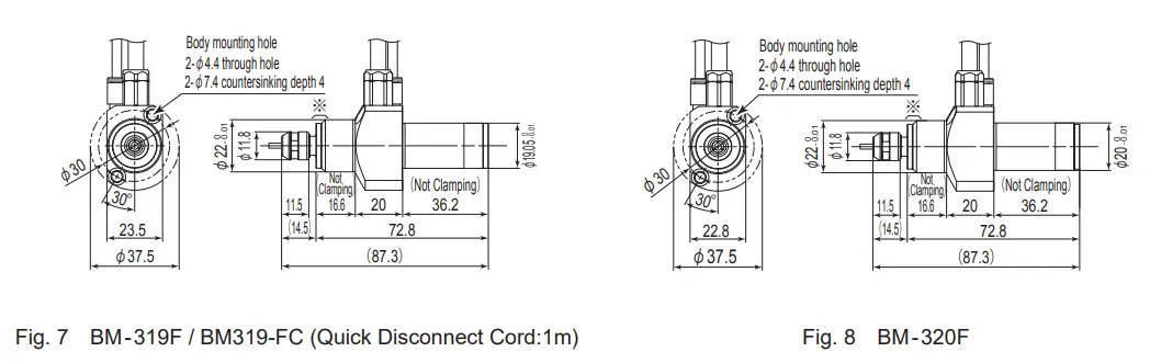
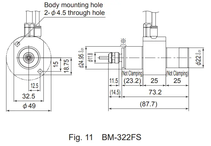
6 – 2 Outside View
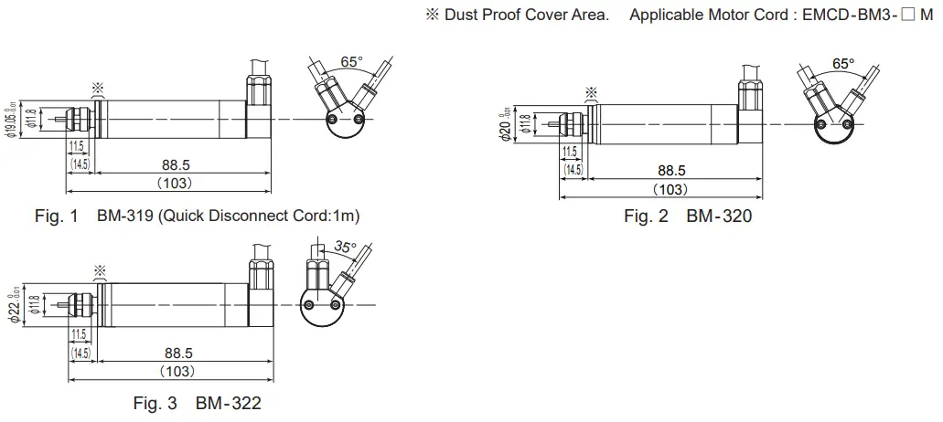
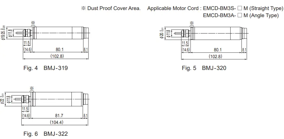
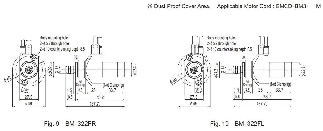
※ Dust Proof Cover Area. Applicable Motor Cord : EMCD-BM3- □ M
Applicable Motor Cord : EMCD-BM3S- □ M (Straight Type) EMCD-BM3A- □ M (Angle Type) ※ Dust Proof Cover Area.
6 – 3 Torque Characteristics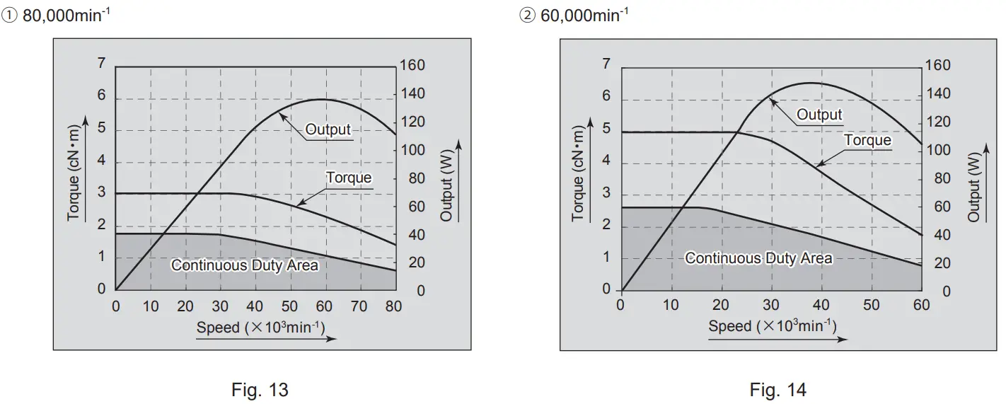
CHANGING THE TOOL
![]() CAUTION
CAUTION
Do not tighten the collet without inserting a tool or dummy bur, as this will damage the collet, spindle or collet nut, causing difficulty removing the collet.
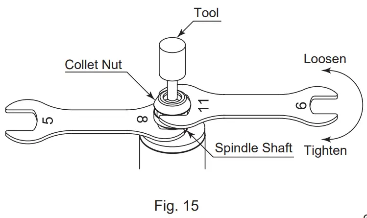
- Set the provided 8mm wrench on the spindle.
- Place the provided 11mm wrench on the collet nut and turn it counterclockwise to loosen the collet and remove the tool.
(The first turn will loosen the collet nut, but the tool will not release and turning will become stiff. Keep turning through the stiffness and the collet will open.) - Clean the collet and collet nut, then insert the new tool and tighten the collet by turning clockwise. Do not over tighten.
REPLACING THE COLLET
CAUTION
When installing the collet in the collet nut, make sure to fully engage the latch inside the collet nut to the groove on the collet outer circumference area. In addition, remember that if the collet is attached without being engaged with the latch of the collet nut, the collet cannot be removed and this may cause damage to the collet or the spindle.
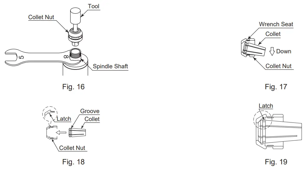
- Remove the tool according to the section 7. “CHANGING THE TOOL” procedure above and remove collet nut assembly (Fig. 16).
- The collet and collet nut are secured by a groove in the collet and a flange in the collet nut. To remove the collet hold the collet nut in one hand and push diagonally down on the collet. The collet should be released (Fig. 17).
- To install the collet, hold the collet at a slight angle, and insert it into the collet nut (Fig. 18).
Press the collet in the collet nut by positioning the collet in the collet nut and pressing down on flat surface (Fig. 17).
Be sure to fully engage the latch inside the collet nut into the groove on the collet outer circumference area (Fig. 19).
CONNECTION OF MOTOR CORD AND AIR SUPPLY
9 – 1 Connection of the Motor Cord
CAUTION
- Before connecting to the Motor Cord Plug, make sure the Main Power Switch on the CONTROLLER is turned OFF. If the Main Power Switch on the CONTROLLER is ON while connecting the Motor Cord Plug, damage may cause to the CONTROLLER.
- Install the connector cover (protective cap etc.) to prevent damage or contamination to the Motor Cord Plug when not in use.
9 – 1 – 1 Connection of the Motor Cord <EMCD-BM3- □M>
The following instructions are for the spindles listed below only:
(BM-319 / BM-319F / BM-319FC / BM-320 / BM-320F / BM-322 / BM-322FR / BM-322FL / BM-322FS)
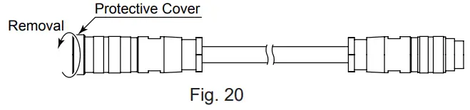
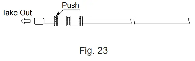
- Remove the Protective Cover of the Motor Cord.

- Ensure Alignment pin upward. Carefully insert the Alignment pin into the Alignment hole and push straight into the motor connector of the Motor Cord Side.
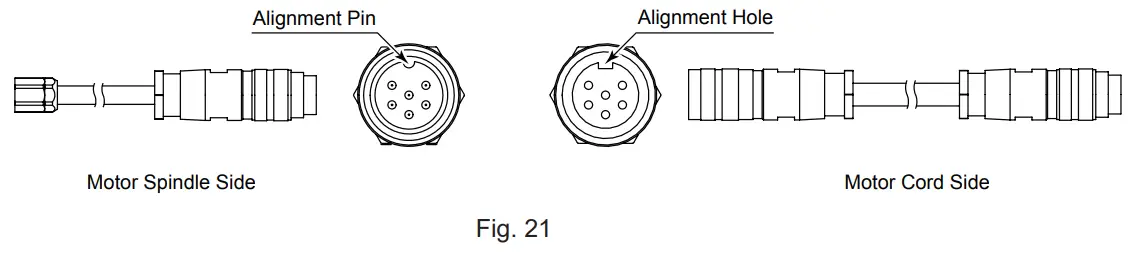
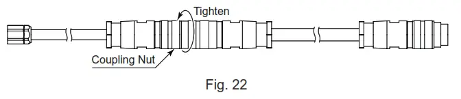
- Tighten the Coupling Nut.
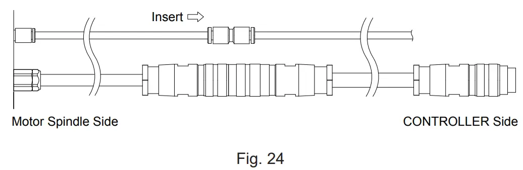
- Remove the protective air inlet quick disconnect cover.

- Insert the provided air hose.
9 – 1 – 2 Connection of the Motor Cord <EMCD-BM3S- □ M / EMCD-BM3A- □ M>
The following instructions are for the spindles listed below only:
(BMJ-319 / BMF-319 / BMJ-320 / BMJ-322)
- Remove the Protective Cover of the Motor Cord.
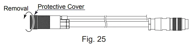
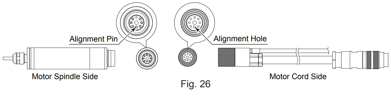
- Ensure alignment pin on the motor is positioned downward. Carefully insert the alignment pin on the motor cord into the alignment hole and push straight into the motor connector.
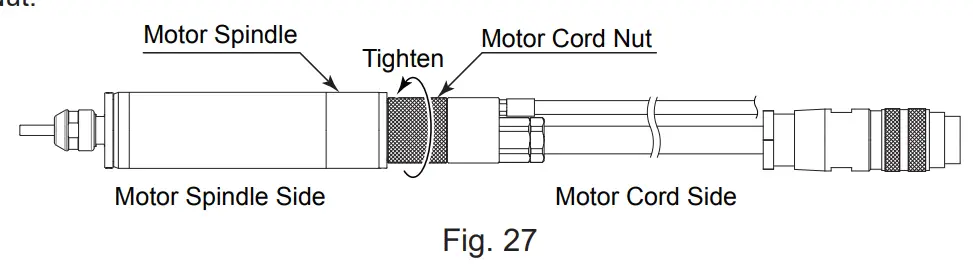
- Tighten the Motor Cord Nut.
9 – 2 Air Supply
The air pressure requirement varies with the number of the motor connections and the length of the hose (quick disconnect cord and motor cord). Verify the number of spindles and cable length before setting the pressure according to Table 1.![]() CAUTION
CAUTION
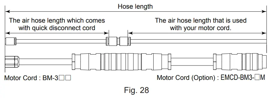
- For BM-319 / BM-319F / BM-319FC / BM-320 / BM-320F / BM-322 / BM-322FR / BM-322FL / BM-322FS “Hose Length” indicates total hose length consisting of the Quick Disconnect Hose and the motor cord hose. See Fig 27 to see how to calculate “Hose Length”.
- When connecting the two motor spindles to the Controller, use the air hose branching joint provided (” Y ” Type) provided with the CONTROLLER. Insert the branching joint into the Air Out quick disconnect on the CONTROLLER.
(Common for all motor spindle models.)
Table 2.
| Total Hose Length (m) *Note 1 | 3.5 | 4.0 | 5.5 | 6.0 | 7.5 | 8.0 | |
| (1) One Motor Spindle is connected to the Control Unit. | Air Pressure (MPa) | 0.2 | 0.25 | 0.3 | |||
| (2) Two Motor Spindles are connected to the Control Unit. | 0.4 | 0.5 | |||||
*Note 1:“Hose Length” indicates total hose length consisting of the Quick Disconnect Hose and the Motor Cord Hose. See Fig.28 to see how to calculate “Hose Length”.
INSTALLATION OF THE MOTOR SPINDLE
![]() WARNING
WARNING
When installing a motor spindle to a fixed base, make sure the fixed base is grounded in order to avoid the risk of an electric shock.![]() CAUTION
CAUTION
When installing a motor spindle, do not hit, drop or cause shock to the spindle. This may cause damage to internal components and result in malfunctions.
10 – 1 Mounting a straight type motor spindle
The following instructions are for the spindles listed below only:
(BM-319 / BMJ-319 / BM-320 / BMJ-320 / BM-322 / BMJ-322)![]() CAUTION
CAUTION
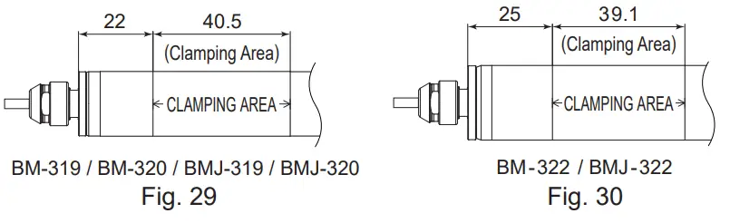
- When mounting the motor spindle, be sure to mounting within clamping area etched on the spindle. If the motor spindle is installed incorrectly, this will cause and damage to the motor spindle.
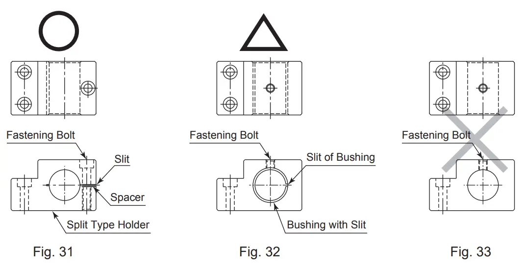
- Cautions when tightening the securing bolt of the Split Type Holder.
Do not over tighten the bolt. This may cause damage to motor spindle’s precision. Tighten the bolt until the spindle body can not be turned by hand within the fixture. Extreme tightening is not necessary or recommended.
Apply working force and check that the motor spindle is tight before using.
- When mounting a motor spindle, refer to the Clamping Area etched on the motor spindle. (Fig. 29, 30)
- When installing a motor spindle to the holder, recommended installation method is shown Fig 31. Refer to ”
How to fabricate the Split Type Holder “. If this is not possible, install as shown in Fig. 32 using the Controllers X10mA function to avoid crushing the motor spindle. CAUTION Do not allow set screws to come directly in contact with the spindle body as shown in Fig. 33, as this will result in damage to the spindle housing and internal components. When installing, never clamp directly over the bearings, as this will result in bearing damage (Refer to Fig. 34).
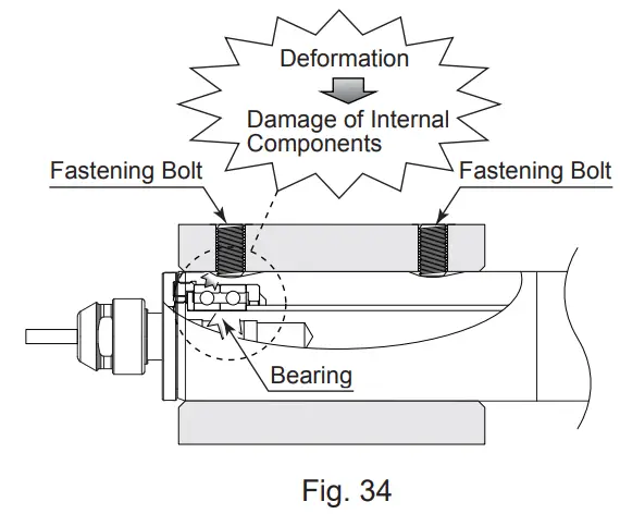
- How to fabricate the Split Type Holder
(1) Roughly process (carve) the inside diameter of the Split Type Holder.
(2) Cut a slit. (Ex. Slit 2mm)
(3) Twist the Screw for Removal and Broaden the Slit Area.
(4) Insert spacer (ex t = 2mm) into the Slit Area.
(5) Loosen the Screw for Removal, and tighten the Fastening Bolt with the specified torque.
(6) Finish machining the Split Type Holder so that the inside diameter of the Split Type Holder is motor spindle’s outside diameter depending on the i-Speed3 motor / spindle model (Refer to Table 2).
The correct tolerance range for the holder is -0.01mm to -0.015mm and a roundness and cylindricity of less than 5μm.
(7) When inserting the motor spindle loosen the Fastening Bolt and twist the Screw for Removal, and broaden the Slit Area.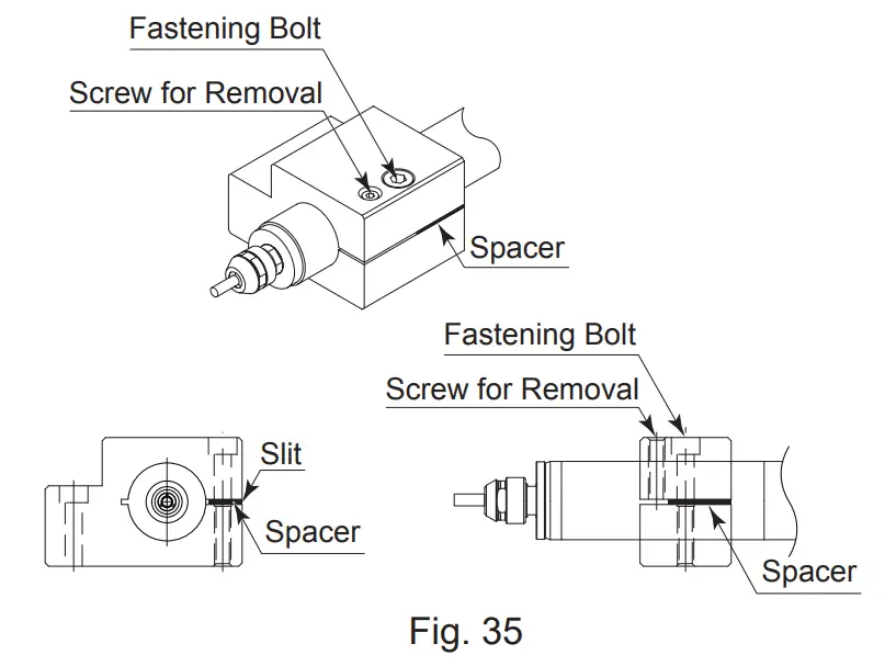 Table 3.
Model BM-319 / BMJ-319 BM- 320 / BMJ- 320 BM-322 / BMJ- 322 φD φ19.05 φ20 φ22 CAUTION
The final responsibility for ensuring holder’s safety for use in a given application is left to the designer of the equipment in which NAKANISHI’s motor spindle is installed.
NAKANISHI offers spindles with a wide variety of capabilities and specifications.
Please carefully check the motor spindle’s specifications against the requirements of your equipment and verify suitability and safety of the Holder prior to initial use. - Motor current display and adjusting the clamping pressure
(1) Motor current display
The Control Unit has a function that displays load on the motor spindle in current (x10mA). (Refer to Front face details ⑩ of the iSpeed3 CONTROLLER Operation Manual). This display allows you to confirm the load / clamping level when fixing the Motor Spindle in fixtures.
(2) Clamping the Motor Spindle
Adjust the clamping pressure level using the motor current display. Run the motor spindle at any speed and note the current level while the motor spindle is not secured in any manner. Insert the motor spindle into the fixture and carefully and slowly tighten.
The Clamped Current Display should never be more than +1 (+10mA) of the current load reading before clamping. This is a very important step when installing the iSpeed3 Motor Spindle.
10 – 2 Fixturing a flange type motor spindle
The following instructions are for the spindles listed below only:
(BM-319F / BM-319FC / BM-320F / BM-322FR / BM-322FL / BM-322FS / BMF-319)![]() CAUTION
CAUTION
If the motor spindle housing diameter section is inserted and tightened using bolts and a solid sleeve or a split holder arrangement, the main body will be geometrically deformed and assembly accuracy will be compromised.
Problems such as rotation failure and heat generation may result.
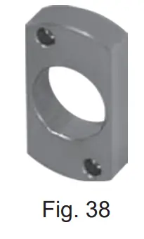
A Flange Type motor spindle can be installed with a flange, without fastening a sleeve over the housing diameter section. This is designed to eliminate deformation / damage of the motor spindle when performing the installation.
- Insert the flange type motor spindle housing diameter area into the fixed base holder of the machine.
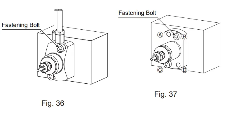
- Secure the motor spindle through the counter-sunk holes on the flange using bolts as shown in Fig. 8, Fig. 9, Fig. 10 and Fig. 11.
Refer to table 4 and Fig. 36 (For BM-319F / BM-319FC / BM- 320F / BM-322FR / BM-322FL / BM-322FS). - Secure the motor spindle through the counter-sunk holes (2 locations : Ⓐ and Ⓓ / Ⓑ and Ⓒ ) on the flange using bolts as shown in Fig. 14. Refer to table 4 and Fig. 37 (For BMF-319).
Table 4.
| Bolt | M4 | (M4 × 25) | BM- 319F / BM- 319FC / BM- 320F |
| (M4 × 16) | BMF- 319 | ||
| M5 | (M5 × 25) | BM- 322FR / BM- 322FL / BM-322FS |
<Option>
- Spacer (10mm)
By using this spacer between the back of the flange and the front the machine’s tool block, it is possible to extend the cutting tool edge forward 10mm (For BM-322FR, BM-322FL).Model SP- 22 × 10L 
- Split Bushings
Bushings allow a φ 22mm BM-322, BMJ-322, BM-322FR, BM322FL, BM-322FS to be mounted into larger diameters. φ 25mm or φ 25.4mm holders.
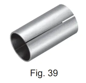
| Model | Inside diameter | Outside diameter |
| RB- 22 × 25 × 34L | φ22mm | φ25mm |
| RB- 22 × 25.4 × 34L | φ22mm | φ25.4mm |
BREAK-IN PROCEDURE
During transportation, storage or installation the grease inside the bearings will settle. If the spindle is suddenly run at high-speed excessive heat will cause bearing damage. After installation, repair, initial operation, or long periods of non operation please follow the break-in procedure detailed in Table 5.
Table 5.
| Steps | 1 | 2 | 3 | 4 | 5 | 6 |
| Rotation Speed (min-1) | 15,000 | 30,000 | 40,000 | 50,000 | 60,000 | 80,000 |
| Rotation time (min) | 15 | 10 | 10 | 10 | 10 | 10 |
| Items to check | No Abnormal Noises | The spindle housing temperature during the break-in process should not exceed 20 degrees C (36 degrees F) above ambient temperature. Should the motor spindle exceed this limit, rest the motor spindle for at least 20 minutes and re-start the break in procedure from the beginning. If the housing temperature rises again and exceeds 20 degrees C (36 degrees F) above ambient temperature, check the motor spindle for proper installation. | The spindle housing temperature during the break-in process should not exceed 20 degrees C (36 degrees F) above ambient temperature. | |||
CAUTIONS WHEN USING GRINDSTONES AND CUTTING TOOLS
CAUTION
The maximum surface speed or rpm is always specified for a grindstone. Do not exceed the maximum speed with reference to the calculating chart below. Always follow the grindstone manufacturers’ recommendations.![]()
- The proper surface speed for general grindstones is 10-30m / s.
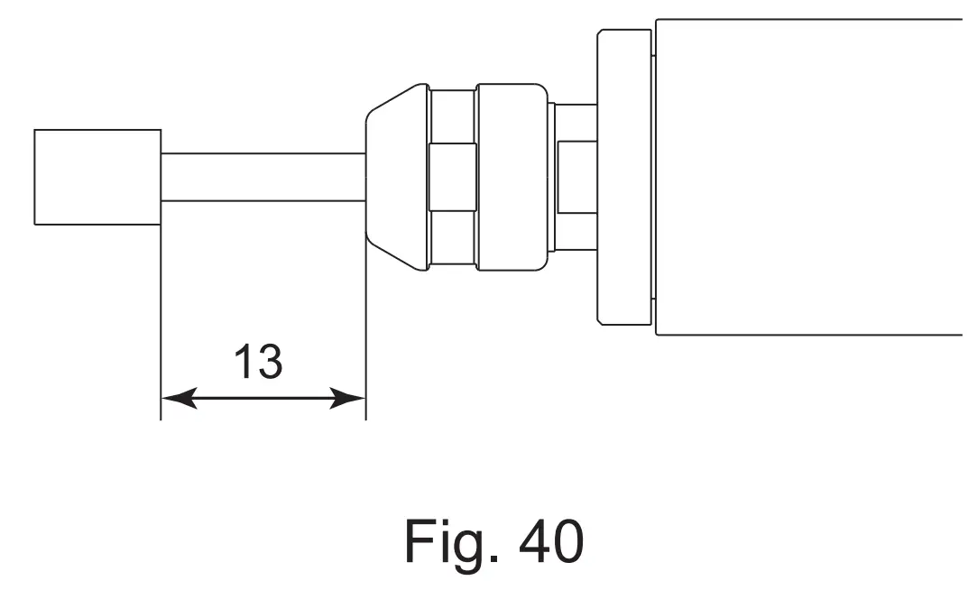
- Do not exceed 13mm of overhang for mounted grindstones as shown in Fig. 40. If the overhang must exceed 13mm, reduce the motor speed in accordance with table 6.
- Dress the grindstone prior to use.
- Do not use cutting tools with bent or broken shanks, cracks or excessive run-out.
- For grinding, the maximum depth of cut should not exceed 0.01mm radially or axially. Reciprocate the tool several times after each pass to eliminate tool pressure.
- Always operate tools within the allowable recommended speed of the tools. Use of a tool outside of the allowable speed of the tools could cause damage to the spindle and injury to the operator.
- Keep the tool shank and collet clean. If contaminants are left in the collet or collet nut, excessive run-out will cause damage to the tool and or spindle.
- Do not strike or disassemble the motor spindle.
- Please set the tools to minimize the overhang amount. 13mm is the maximum amount of overhang to maintain high accuracy and safety.
Table 6. Overhang and Speed
| Overhang (mm) | Max. Speed (min -¹) |
| 20 | N x 0.5 |
| 25 | N x 0.3 |
| 50 | N x 0.1 |
N = Max. Operating Speed with 13mm overhang.
TROUBLE SHOOTING
If a problem or concern occurs, please check the following prior to consulting your dealer.
| Trouble | Cause | Inspection / Corrective Action |
| Spindle does not rotate or rotate smoothly. | The ball bearings are damaged. | Replace the ball bearings. (Return to NAKANISHI dealer service.) |
| Motor is broken. | Replace the motor. (Return to NAKANISHI dealer service.) | |
| Overheating during rotation. | Cutting debris has contaminated the ball bearing, and the ball bearing is damaged. | Replace the ball bearings. (Return to NAKANISHI dealer service.) |
| Low air pressure. | Check air hose connection and air pressure. | |
| Abnormal vibration or noise during rotation. | Using bent tool. | Replace the tool. |
| Cutting debris has contaminated the ball bearing. | Replace the ball bearings. (Return to NAKANISHI dealer service.) | |
| The ball bearings are worn. | ||
| Tool slippage. | Collet or collet nut are not correctly installed. | Check and clean the collet and collet nut. And, tighten the collet accurately again. |
| The collet and the collet nut are worn. | Replace the collet and collet nut. | |
| High run-out. | The tool is bent. | Change the tool. |
| Collet nut is not correctly installed. | Secure the collet and the collet nut correctly. | |
| The collet and the collet nut are worn. | Replace the collet and the collet nut. | |
| Inside of the spindle is worn. | Replace the spindle shaft. (Return to NAKANISHI dealer service.) | |
| Contaminants inside the collet and the collet nut or the spindle. | Clean the collet, collet nut and the inside of the spindle. | |
| The ball bearings are worn. | Replace the ball bearings. (Return to NAKANISHI dealer service.) |
DISPOSAL OF THE MOTOR SPINDLE
When disposal of a Motor Spindle is necessary, follow the instructions from your local government agency for proper disposal of electrical components .
NAKANISHI INC.
700 Shimohinata, Kanuma
Tochigi 322-8666 Japan
www.nakanishi-inc.com
NSK America Corp.
1800 Global Parkway
Hoffman Estates IL 60192, USA
www.nskamericacorp.com
NSK Europe GmbH![]()
Elly-Beinhorn-Strasse8 65760 Eschborn Germany
NSK United Kingdom Ltd.
UK Authorised Representative
Office 4, Gateway 1000 Arlington Business Park, Whittle Way
Stevenage, SG1 2FP, UK
Contents are subject to change without notice.


