
![]()
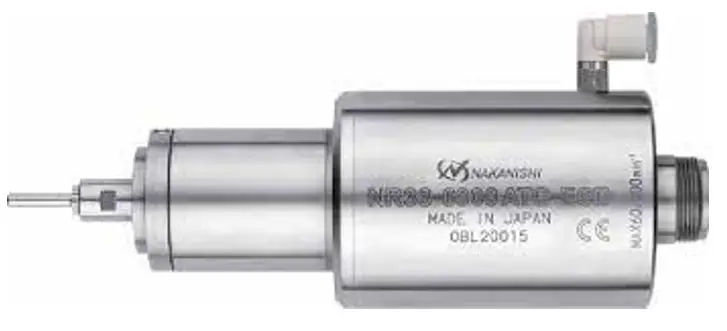
Motor Spindle
OM-KK0951EN 000
EM20-S6000・EM25-S6000
EM30-S6000
OPERATION MANUAL
EM Series Motor Spindle
Thank you for purchasing Motor Spindle ” EM20 – S6000 ・EM25 – S6000 ・EM30 – S6000 “. These Motor Spindles are designed for grinding, small diameter drilling and milling, etc. The E3000 CONTROLLER and Air Line Kit are required to drive this Motor Spindle. Read this and all the associated component Operation Manuals carefully before use. Always keep this Operation Manual in a place where a user can referred to for reference at any time.
CAUTIONS FOR HANDLING AND OPERATION
■ Read these warnings and cautions carefully and only use in the manner intended.
■ These warnings and cautions are intended to avoid potential hazards that could result in personal injury to the operator or damage to the device. These are classified as follows in accordance with the seriousness of the risk.
| Class | Degree of Risk |
| A safety hazard could result in bodily injury or damage to thedevice if the safety instructions are not properly followed. | |
| A hazard that could result in light or moderate bodily injury or damage to the device if the safety instructions are not followed. |
![]() WARNING
WARNING
① This Motor Spindle is not a hand tool. It is designed to be used on CNC machines or special purpose machines.
② Do not touch the cutting tool while it is running. It is very dangerous.
③ Wear safety glasses, dust mask, and use a protective cover around the Motor Spindle whenever the Motor Spindle is rotating.
④ Never connect, disconnect or touch the Power Cord Plug or Motor Cord Plug with wet hands. This may cause an electric shock.
⑤ Never operate or handle the Motor Spindle until you have thoroughly read the Operation Manuals and safe operation has been confirmed.
1)To prevent injuries / damages, check the Motor Spindle and cutting tool for proper installation, before operating the Motor Spindle.
2)Before disconnecting the Motor Spindle, always turn the control power off and turn the compressed air supply to the CONTROLLER off. Then it is safe to remove the Motor Spindle.
⑥ Whenever installing a Motor Spindle to a fixed metal base, ensure that the fixed metal base is grounded in order to avoid risk of an electric shock.
⑦ When installing a tool, tighten the collet correctly and check again the collet and collet nut before use. Do not over-tighten the collet. This may cause damage to the spindle.
⑧ Do not use bent, broken, chipped, out of round or sub-standard tools, as this may cause them to shatter or explode. Tools with fractures or a bent shank will cause injury to the operator. When using a new tool, rotate it in a low speed and increase speed gradually for safety.
⑨ Do not exceed the maximum recommended allowable tool speed. For your safety, use speeds below the maximum allowable speed.
⑩ Do not apply excessive force. This may cause injury to the operator by slippage or damage of the tool, or loss of concentricity and precision of the Motor Spindle.
![]() CAUTION
CAUTION
① Do not drop or hit this Motor Spindle, as shock can damage to the internal components.
② Be sure to clean the collet and collet nut, the inside of the spindle before replacing the tool. If ground particles or metal chips stick to the inside of spindle or the collet, damage to the collet or spindle can occur due to the loss of precision.
③ When cleaning a Motor Spindle, stop the Motor Spindle and remove debris with a soft brush or a cloth. Do not blow air into the dust proof cover area (refer to section ” 6 – 2 Outside View “) with compressed air as foreign particles or cutting debris may get into the ball bearing.
④ Always clean the tool shank before installing the tool in the spindle.
⑤ When sizing the correct collet size to the tool shank diameter, a tolerance of +0 ~ – 0.01mm is strongly recommended.
A tool shank within the +0 ~ – 0.1mm range is mountable, however, this may cause poor concentricity and or insufficient tool shank gripping force.
⑥ Select suitable products or tools for all applications. Do not exceed the capabilities of the Motor Spindle or tools.
⑦ Do not stop the supply cooling air for Motor Spindle during operation of the machine.
Removing the air pressure from the Motor Spindle causes a loss of purging, allowing the Motor Spindle to ingest coolant. This will cause damage to the Motor Spindle.
⑧ Carefully direct coolant spray to the tool. Do not spray directly on the Motor Spindle body. If large amount spray directly on the Motor Spindle, it may cause excess load of the motor rotation with loss of durability to the Motor Spindle.
⑨ Stop working immediately when abnormal rotation or unusual vibration are observed. Immediately, please check the content of section ” 13. TROUBLESHOOTING “.
⑩ Always check if the tool, collet, collet nut, connection hose and supply air / oil hose for damaged before and after operating.
⑪ If the collet or collet nut show signs of wear or damage, replace them before a malfunction or additional damage occurs.
⑫ After installation, repair, initial operation, or long periods of non operation, please refer to section ” 11. BREAK-IN PROCEDURE ” detailed in Table. 4. When checking the Motor Spindle, no vibration or unusual sound should be observed during rotation.
⑬ Do not disassemble, modify or attempt to repair this Motor Spindle. Additional damage will occur to the internal components. Service must be performed by NSK NAKANISHI or an authorized service center.
⑭ When using this Motor Spindle for mass production, please consider the purchase of an additional Motor Spindle to be used as a back-up in case of emergency.
⑮ Securely connect the compressor supply connection hose and the air hose to the Air Line Kit and the Motor Spindle to avoid accidental disconnection during use.
BASIC PACKAGE
When opening the package, check if it includes all items listed in ” Table. 1 Packing List Contents “.
In the event of any shortage, please contact either NAKANISHI (see the ” 4. CONTACT US ” section) or your local dealer.
Table. 1 Packing List Contents
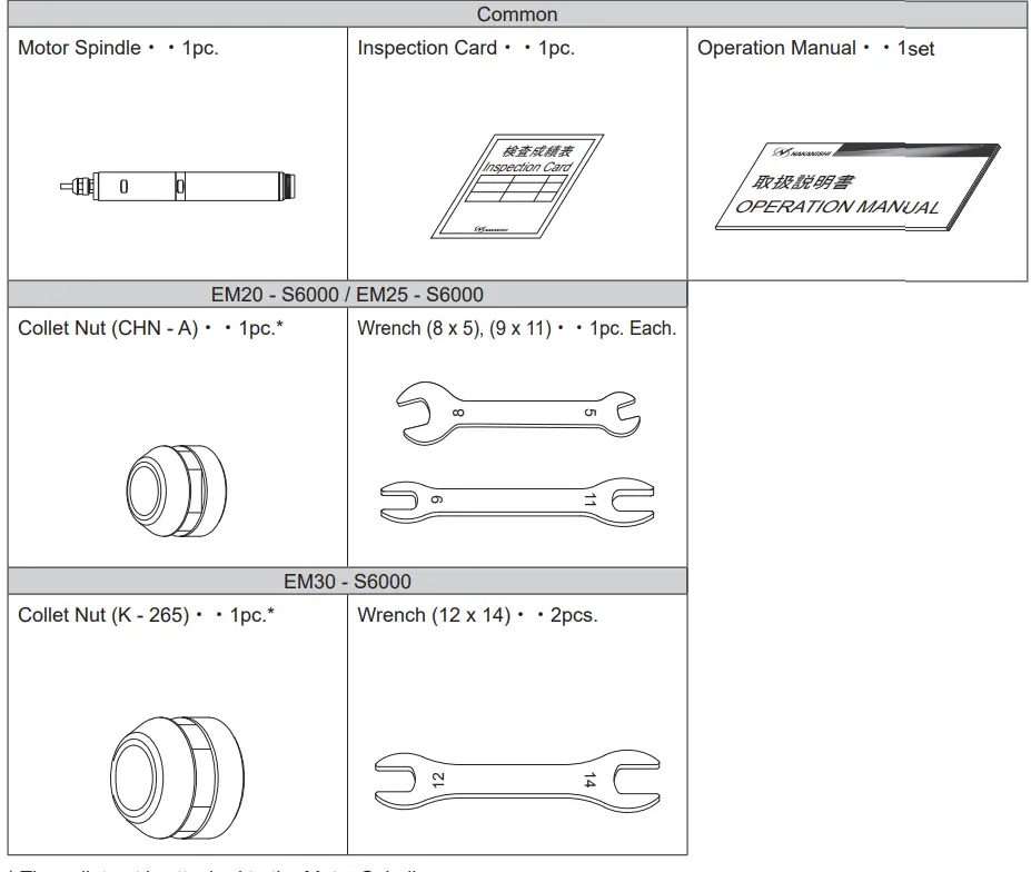
* The collet nut is attached to the Motor Spindle.
WARRANTY
We provide a limited warranty for our products. We will repair or replace the products if the cause of failure is due to the following manufactures defects. Please contact us or your local distributor for details.
- Defect in manufacturing.
- Any shortage of components in the package.
- Where damaged components are found when initially opening the package.
(This shall not apply if the damage was caused by the negligence of a customer.)
CONTACT US
For your safety and convenience when purchasing our products, we welcome your questions.
If you have any questions about operation, maintenance and repair of the product, please contact us.
Contact Us
| For U.S. Market Company Name Business Hours U.S. Toll Free No. Telephone No. Fax No. Website | : NSK America Corp. Industrial Div. : 8:00 to 17:00 (CST) (closed Saturday, Sunday and Public Holidays) : +1 800 585 4675 : +1 847 843 7664 : +1 847 843 7622 : www.nskamericacorp.com |
| For Other Markets Company Name Business Hours Telephone No. | : NAKANISHI INC. : 8:00 to 17:00 (JST) (closed Saturday, Sunday and Public Holidays) : +81 289 64 3520 : [email protected] |
FEATURES
① The Motor Spindle housing is made from precision ground, hardened, stainless steel (SUS) with an outside diameter of φ20mm, φ25mm and φ30mm.
② Excellent durability and high reliability are obtained by using a high-speed brushless motor, which eliminates the need for brush replacement and frequent maintenance.
③ Easy to be attached to NC lathe or to replace the Motor Spindle, because the connector is placed at the edge of the motor.
④ Various sizes of collets are available CHA 0.5mm – 4.0mm or CHK 0.5mm – 6.0mm. Standard collet is 3.0mm (CHA / CHK) or 3.175mm (CHA / CHK). (For U.S. market 3.175mm (CHA / CHK)).
SPECIFICATIONS AND DIMENSIONS
6 – 1 Specifications
| Model | EM20 – S6000 | I EM25 – S6000 | I EM30 – S6000 |
| Maximum Motor Rotation Speed | 60,000min-1(rpm) | ||
| Spindle Accuracy | Less than 1pm | ||
| Outside diameter | Ø 20mm | Ø25mm | Ø 30mm |
| Max. Output | 250W | 350W | |
| Weight | 230g | I 375g | 575g |
| Noise Level at lm distance | Less than 70dB (A) | ||
| Temperature | Humidity | Atmospheric Pressure | |
| Operation Environment | 0 – 40°C | MAX.75% (No condensation) | 800 – 1,060hPa |
| Transportation and Storage Environment | -10 – + 50°C | 10 – 85% | 500 – 1,060hPa |
<Option>
| Motor Cord *Note 1 | Length : 4m, 6m, 8m (The Air Hose ( Ø4mm) of the same length is attached.) |
| Collet (CHA – □ □ ) *Note 2 (EM20 – S6000 / EM25 – S6000 ) | 00.5mm – Ø4.0mm in 0.1mm increments and Ø2.35mm, 03.175mm |
| Collet (CHK – □ □ ) *Note 2 (EM30 – S6000) | Ø0.5mm – Ø6.0mm in 0.1mm increments and Ø2.35mm, Ø3.175mm, Ø4.76mm, Ø6.35mm |
*Note1 :Motor Cord is sold separately. Please select the suitable motor cord length for your application.
*Note2 :Collet is sold separately. Please select the suitable collet size for your application.
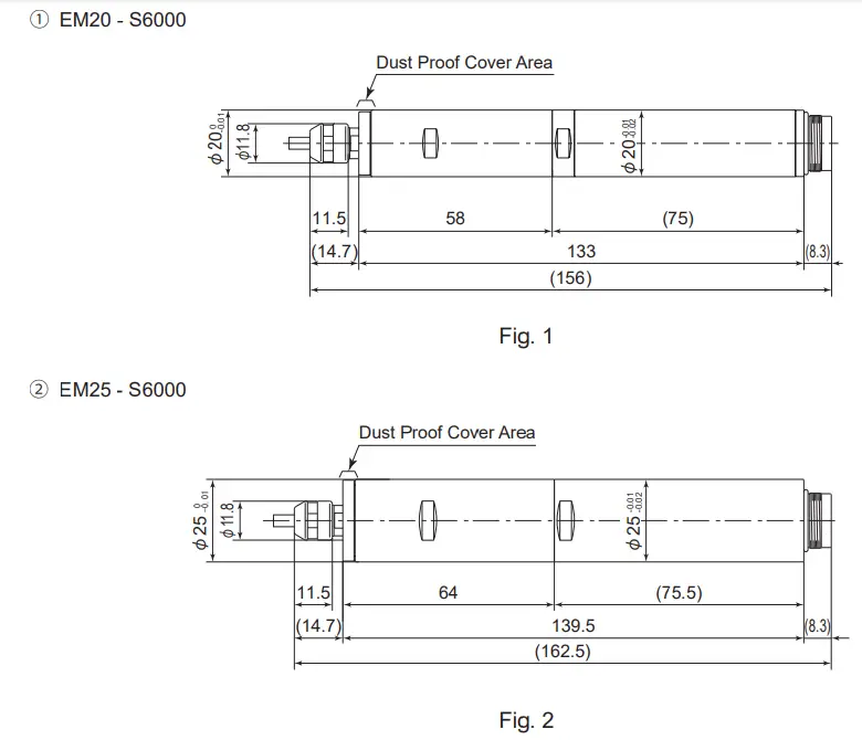
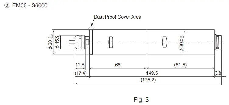
6 – 2 Outside View
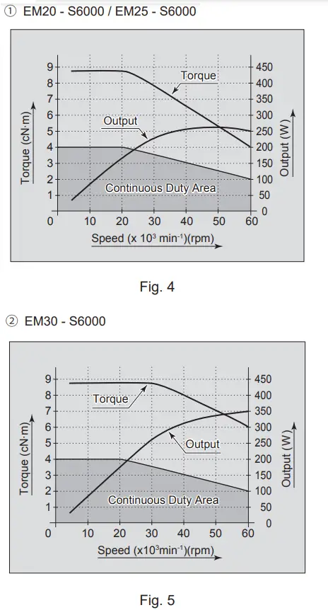
6 – 3 Torque Characteristics
CHANGING THE TOOL
![]() CAUTION
CAUTION
Do not tighten the collet without inserting a tool or dummy bur, as this will damage the collet, spindle or collet nut, causing difficulty removing the collet.
RECOMMENDATION
Please set the cutting tools to minimize the overhang amount. 13mm is the maximum amount of overhang to maintain high accuracy and safety.
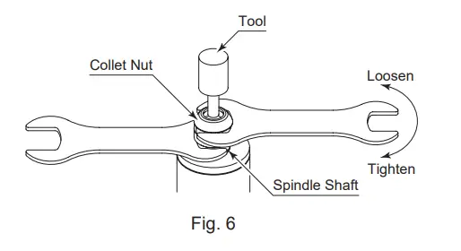
① Set the provided wrench (EM20 – S6000 / EM25 – S6000 : 8mm, EM30 – S6000 : 12mm) on the spindle.
② Place the provided wrench (EM20 – S6000 / EM25 – S6000 : 11mm, EM30 – S6000 : 14mm) on the collet nut and turn it counterclockwise to loosen the collet and remove the tool (The first turn will loosen the collet nut, but thetool will not release and turning will become stiff. Keep turning through the stiffness and the collet will open).
③ Clean the collet and collet nut, then insert the new tool and tighten the collet by turning clockwise. Do not overtighten.
REPLACING THE COLLET
![]() CAUTION
CAUTION
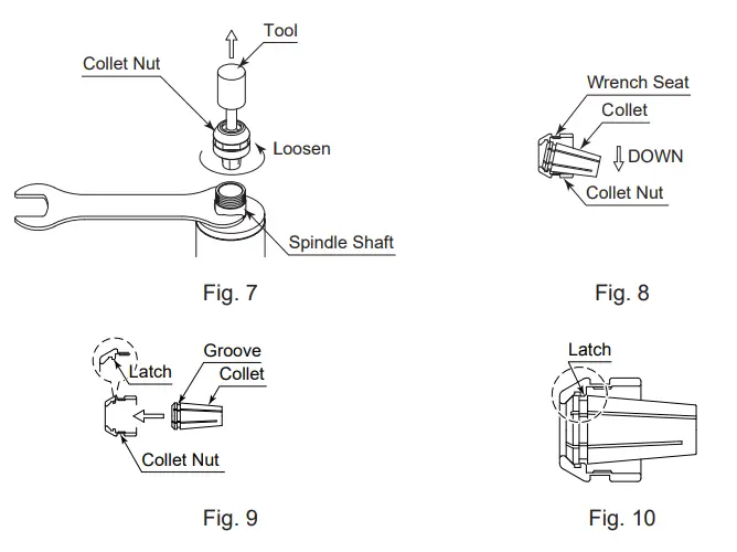
When installing the collet into the collet nut, be sure to fully engage the latch inside the collet nut to the groove on the collets outer diameter area. In addition, remember that if the collet is attached without being engaged with the latch of the collet nut, the collet cannot be removed and this may cause damage to the collet or the spindle.
① Remove the tool according to the section ” 7. CHANGING THE TOOL ” procedure above and remove collet nut assembly (Fig. 7).
② The collet and collet nut are secured by a groove in the collet and a flange in the collet nut. To remove the collet hold the collet nut in one hand and push diagonally down on the collet. The collet should be released (Fig. 8).
③ To install the collet, hold the collet at a slight angle, and insert it into the collet nut (Fig. 9).
Press the collet in the collet nut by positioning the collet in the collet nut and pressing down on flat surface (Fig. 8).
Be sure to fully engage the latch inside the collet nut into the groove on the collets outer circumference area (Fig. 10).
CONNECTION OF MOTOR CORD
![]() CAUTION
CAUTION
- Before connecting to the Motor Cord to the Motor and CONTROLLER, verify the Main Power Switch in the CONTROLLER is turned OFF. If the Main Power Switch on the CONTROLLER is ON while connecting the Motor Cord, damage to the CONTROLLER is possible.
- Install the Protective Cap etc. to prevent damage or contamination to the Motor Cord Plug when not in use.
① Remove the Protective Cover of the Motor Cord Plug and keep it for use when not using the Motor / Spindle tokeep the connector pins safe and clean.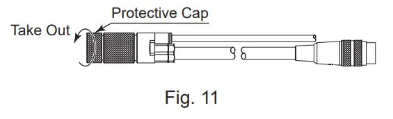
② Ensure the Alignment Pin of the Motor Cord Connector is located (12 o-clock) upward. Carefully insert the Alignment Pin of Motor Cord Plug into the Alignment Hole on the front(rear) of the CONTROLLER and push straight.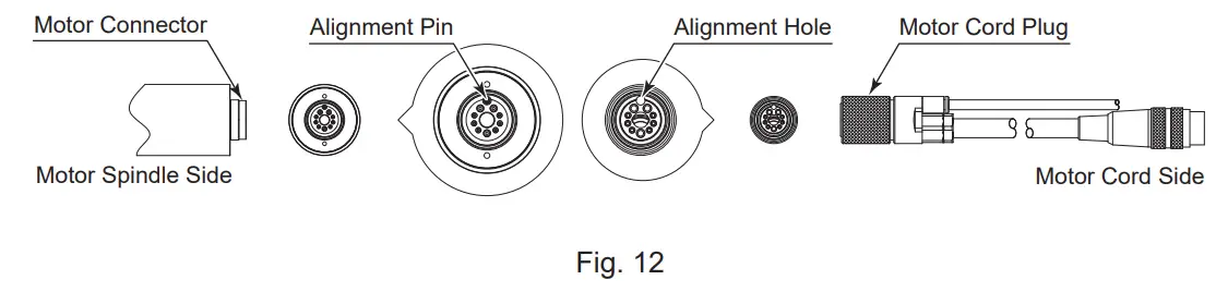
③ Tighten the Connector Nut of the Motor Cord in a clockwise direction.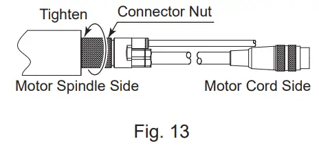
INSTALLATION OF THE MOTOR SPINDLE
![]() WARNING
WARNING
When installing a Motor Spindle to a fixed base, make sure the fixed base is grounded in order to avoid the risk of an electric shock.
![]() CAUTION
CAUTION
- When installing a Motor Spindle, do not hit, drop or cause shock to the Motor Spindle. This may cause damage to internal components and result in malfunctions.
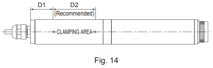
- When mounting the Motor Spindle, be sure to secure within Clamping Area etched on the Motor Spindle O.D. If the Motor Spindle is installed incorrectly, damage to the internal components is possible.
- Cautions when tightening the securing bolts on to a Split Type Holder Do not over-tighten the bolt. This will cause damage to Motor Spindle’s ecision.
Tighten the bolt until the Motor Spindle body can not be rotated by hand within the fixture.
Extreme tightening is not necessary or recommended.
Apply working force and check that the Motor Spindle is tight before using.
① When mounting a Motor Spindle, refer to the Clamping Area etched on the Motor Spindle (Fig. 14).
Table. 2
| Model | D1 | D2 |
| EM20 – S6000 | 18 | 34 |
| EM25 – S6000 | 22 | 30 |
| EM30 – S6000 | 20 | 36 |
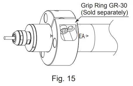
* When installing a EM30 – S6000, using ” Grip Ring GR – 30 (sold separately) ” (Fig. 15) is recommended. If the Grip Ring GR – 30 (sold separately) cannot be used due to the restriction of dimension and space, and when installing a EM25 – S6000 / EM20 – S6000, install as shown in ② below.
② When installing a Motor Spindle to the holder, recommended installation method is shown Fig. 16. Refer to ” ③ How to fabricate the Split Type Holder “. If this is not possible, install as shown in Fig. 17.
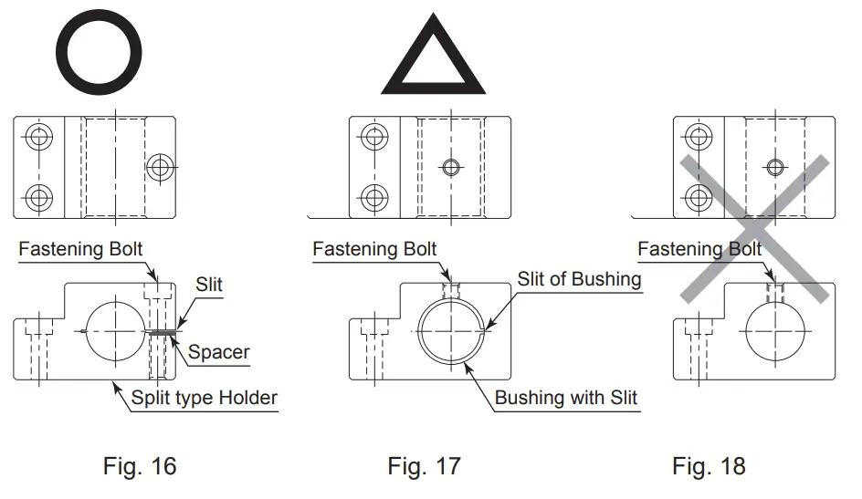
![]() CAUTION
CAUTION
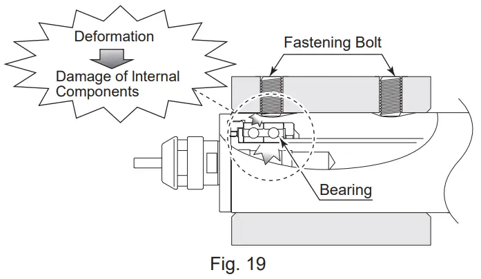
Do not allow set screws to come directly in contact with the Motor Spindle body as shown in Fig. 18, as this will result in damage to the Motor Spindle housing and internal components. When installing, never clamp directly over the bearings, as this will result in bearing damage (Refer to Fig. 19).
③ How to fabricate the Split Type Holder
(1) Rough bore the inside diameter of the Split Type Holder.
(2) Cslit. (Ex. Slit 2mm) wide.
(3) Tighten the Screw for Removal and Force Open the Slit Area.
(4) Insert a spacer (Ex. thickness = 2mm) into the Slit Area.
(5) Loosen the Screw for Removal, and tighten the fastening bolt with its specified torque.
(6) Finish the Split Type Holder so that the inside diameter of the Split Type Holder is Motor Spindle’s outside diameter (Refer to Table 3). The correct tolerance range for the holder is – 0.01mm to – 0.015mm and a roundness and cylindricity of less than 5μm.
Table. 3
| Model | EM20 – S6000 | EM25 – S6000 | EM30 – S6000 |
| Motor Spindle’s outside diameter | φ20 | φ25 | φ30 |
(7) When inserting the Motor Spindle loosen the Fastening Bolt, and tighten the Screw for Removal, widening the Slit Area.

![]() CAUTION
CAUTION
- How to confirm the correct tightening or clamping of the Motor Spindle in the holder Measure the current value of the CONTROLLER’s power cord by the clamp meter. Fasten the holder so that the increase in the no-load current value (during rotation at the maximum rotation speed) with the Motor Spindle fastened is 20mA (for type 120V) / 10mA (for type 200V / 230V) or less, compared to the no-load current value (during rotation at the maximum rotation speed) without fastening the Motor Spindle. Do not over-tighten the Fastening Bolt. It may damage Motor Spindle’s precision and shorten the life of the bearings.
- The final responsibility for ensuring holderʼs safety for use in a given application is left to the designer of the equipment in which NAKANISHI’s Motor Spindle is installed. NAKANISHI offers Motor Spindle with a wide variety of capabilities and specifications. Please carefully check the Motor Spindle’s specifications against the requirements of your equipment and verify suitability and safety of the Holder prior to initial use.
BREAK-IN PROCEDURE
During transportation, storage or installation, the grease inside the bearings will settle. If the Motor Spindle is suddenly run at high-speed, the grease will be ejected from the bearings, causing excessive heat that will cause bearing damage.
After installation, repair, initial operation, or long periods of non operation, please follow the break-in procedure detailed in Table 4.
Table. 4
| Steps | 1 | 2 | 3 | 4 | 5 |
| Rotation Speed (min-1) (rpm) | 15,000 | 30,000 | 40,000 | 50,000 | 60,000 |
| Rotation Time (min) | 15 | 10 | 10 | 10 | 10 |
| Items to Check | No Abnormal Noises | The Motor Spindle housing temperature during the break-in process should not exceed 20 degrees C (36 degrees F) above ambient temperature. Should the Motor Spindle exceed this limit, rest the Motor Spindle for at least 20 minutes and re-start the break in procedure from the beginning. If the housing temperature rises again and exceeds 20 degrees C (36 degrees F) above ambient temperature, check the spindle and motor for proper installation. | The Motor Spindle housing temperature during the break-in process should not exceed 20 degrees C (36 degrees F) above ambient temperature. | ||
CAUTIONS WHEN USING GRINDSTONES AND TOOLS
![]() CAUTION
CAUTION
The maximum surface speed or rpm is always specified for a grindstone. Do not exceed the maximum speed with reference to the calculating chart below. Always follow the grindstone manufacturer’s recommendations.
Surface Speed (m / s) = 3.14 x Diameter (mm) x Rotation Speed (min-1) (rpm)
1,000 x 60
① The proper surface speed for general grindstones is 10 – 30m / s.
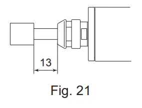
② Do not exceed 13mm of overhang for mounted grindstones as shown in Fig. 21. If the overhang must exceed 13mm, reduce the motor speed in accordance with Table. 5.
③ Dress the grindstone prior to use.
④ Do not use cutting tools with bent or broken shanks, cracks or excessive run-out.
⑤ For grinding, the maximum depth of cut should not exceed 0.01mm radially or axially. Reciprocate the tool several times after each pass to eliminate tool pressure.
⑥ Always operate cutting tools within the allowable recommended speed of the cutting tools. Use of a cutting tool outside of the allowable speed of the cutting tools could cause damage to the spindle and injury to the operator.
⑦ Keep the cutting tool shank and collet clean. If contaminants are left in the collet or collet nut, excessive runout will cause damage to the cutting tool and or spindle.
⑧ Do not strike or disassemble the Motor Spindle.
⑨ Please set the cutting tools to minimize the overhang amount. 13mm is the maximum amount of overhang to maintain high accuracy and safety.
Table. 5 Overhang and Speed
| Overhang (mm) | Max. Speed (min-1) (rpm) |
| 20 | N x 0.5 |
| 25 | N x 0.3 |
| 50 | N x 0.1 |
TROUBLESHOOTING
If a problem or concern occur, please check the following items prior to consulting your dealer.
| Trouble | Cause | Inspection / Corrective Action |
| Motor Spindle does not rotate or rotate smoothly. | The Motor Spindle ball bearings have been damaged. | Replace the ball bearings. (Return to NAKANISHI dealer service.) |
| The motor has been damaged. | Replace the motor. (Return to NAKANISHI dealer service.) | |
| Overheating during rotation. | Cutting debris has contaminated the ball bearings, and the ball bearings are damaged. | Replace the ball bearings. (Return to NAKANISHI dealer service.) |
| Low air pressure. | Check air hose connection and air pressure. | |
| Abnormal vibration or noise during rotation. | The tool shank is bent. | Replace the tool. |
| Cutting debris has contaminated the ball bearing. | Replace the ball bearings. (Return to NAKANISHI dealer service.) | |
| The Motor Spindle ball bearings have been damaged. | ||
| Tool slippage. | Collet or collet nut are not correctly installed. | Check and clean the collet and collet nut. Reinstall the collet and collet nut. |
| The collet and the collet nut are worn. | Replace the collet and collet nut. | |
| High run-out. | The tool is bent. | Change the tool. |
| Collet nut is not correctly installed. | Secure the collet and the collet nut correctly. | |
| The collet and the collet nut are worn. | Replace the collet and the collet nut. | |
| Inside of the spindle is worn. | Replace the spindle shaft. (Return to NAKANISHI dealer service.) | |
| Contaminants inside the collet and the collet nut or the spindle. | Clean the collet, collet nut and the inside of the taper and spindle. | |
| The Motor Spindle ball bearings have been damaged. | Replace the ball bearings. (Return to NAKANISHI dealer service.) |
Refer to the E3000 CONTROLLER Operation Manual.
DISPOSAL OF THE MOTOR SPINDLE
When disposal of a Motor Spindle is necessary, follow the instructions from your local government agency for proper disposal of industrial components.
| NAKANISHI INC. 700 Shimohinata, Kanuma Tochigi 322-8666 Japan www.nakanishi-inc.com | NSK America Corp. 1800 Global Parkway Hoffman Estates IL 60192, USA www.nskamericacorp.com | NSK Europe GmbH Elly-Beinhorn-Strasse 8 65760 Eschborn Germany | NSK United Kingdom Ltd. UK Authorised Representative Office 4, Gateway 1000 Arlington Business Park,WhittleWay Stevenage, SG12FP, UK |
Contents are subject to change without notice.


