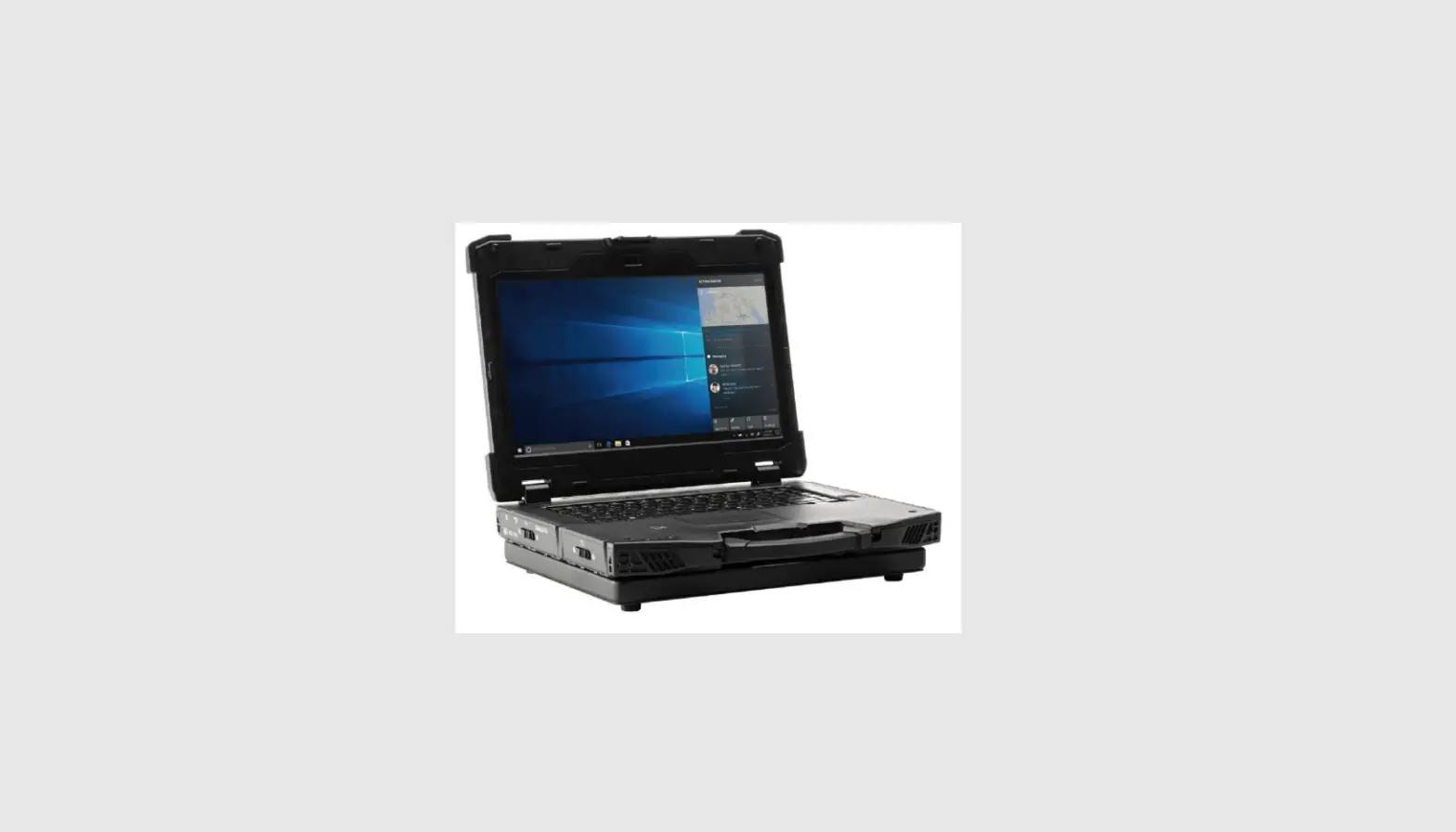
DURABOOK Z141 Laptop Discrete VGA Expansion Chassis

Package Contents
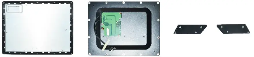
If any of the following items are damaged, please contact your retailer.
- Adapter
- Power code

- Expansion chassis with Rubber gasket
- Bottom cover with PCIe cables
- Expansion brackets (2)
| Screw Name | Screw Type | Quantity |
| ISOT-M3.0X10L |  | 6 (bumpers) |
| ISOT-M3.0X7L |
| 8 (bumpers) |
| ISOT-M2.6X3L | 
| 4 (expansion chassis) |
| ISOT-M2.6X8L & O RING |  | 6 (expansion chassis) |
| ISOT-M2.6X4L |  | 4 (expansion brackets) |
| 14 (bottom cover) |
NOTE: The pictures are for reference only, actual items may slightly differ.
Installation
- This section will guide you on how to install the discrete VGA expansion chassis to your notebook.
NOTE: For Z14I laptop equipped with discrete NVIDIA graphic MXM expansion box, a 120W power adapter must be use.
Installing the Discrete VGA Expansion Chassis
To install the expansion chassis, follow the steps below: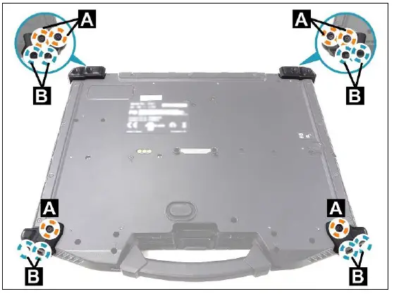
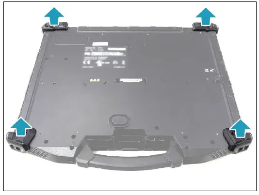
- Remove the 14 screws securing the bumpers.
- ISOT-M3.0X10L (A): 6 screws
- ISOT-M3.0X7L (B): 8 screws
- Remove the bumpers.

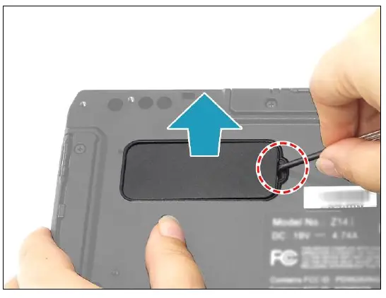
- Pry to remove the mylar from the lower case.

- By aligning with the screw holes, install the expansion brackets onto their respective slots.
NOTE: Ensure that the 4 O-rings ( ) are properly embedded in the upper part of the screw holes (C).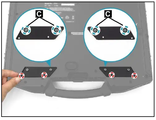
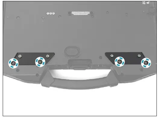
- Attach the 4 screws (ISOT-M2.6X4L) to secure the expansion brackets to the lower case.

- Place the expansion chassis on the top of the lower case. Ensure that the screw holes are properly aligned.
NOTE: If you have difficulty aligning the screw holes, lift the chassis and loosen the 4 screws securing the expansion brackets (see Step 5). Then place the chassis onto the lower case and re-align the screw holes (D) with the screw holes on the brackets. After verifying the screws holes are properly aligned, lift the chassis again, and then fasten the 4 screws to secure the expansion brackets.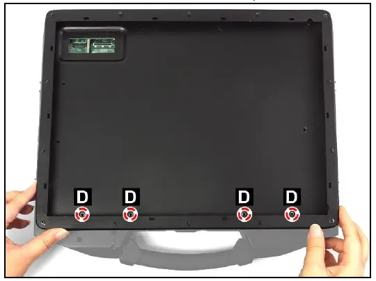
- Attach the 4 screws (ISOT-M2.6X3L) first to secure the expansion chassis to the lower case. Then continue to attach the remaining 6 screws (ISOT-M2.6X8L).
- ISOT-M2.6X3L (F): 4 screws
- ISOT-M2.6X8L (E): 6 screws

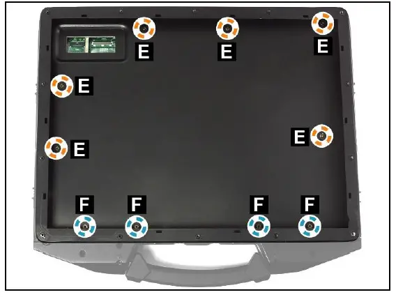
NOTE: Ensure that the O-ring is embedded with the ISOT-M2.6X8L screw.
- With the protruding tabs facing down, install the rubber gasket onto its compartment. Press down each tabs to ensure that the gasket is properly seated in place.
CAUTION: To ensure the correct placement and orientation, please observe the printed direction (G) when installing the rubber gasket.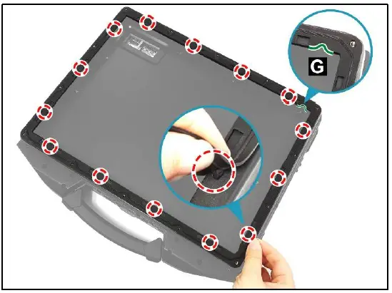
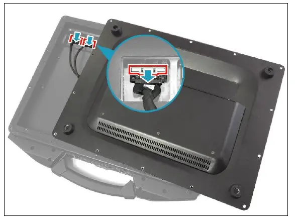
- Connect the PCIe coaxial cable to the mainboard connector. Then connect the PCIe power cable to the mainboard connector and secure the latch.

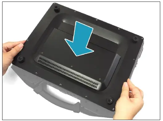
- Place the bottom cover onto the chassis.

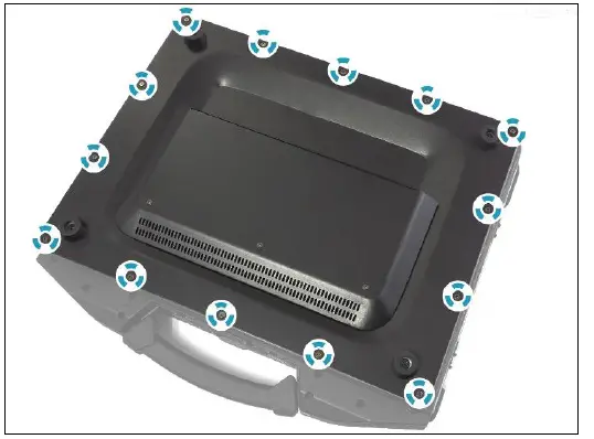
- Attach the 14 screws (ISOT-M2.6X4L) to secure the bottom cover.

Discrete VGA Expansion Chassis Screws
| Screw Name | Screw Type | Quantity | Torque |
| ISOT-M3.0X10L | | 6 (bumpers) | 2.5 ± 0.3 Kgf-cm |
| ISOT-M3.0X7L | 8 (bumpers) | 2.5 ± 0.3 Kgf-cm | |
| ISOT-M2.6X3L |
| 4 (expansion chassis) | 2.5 ± 0.3 Kgf-cm |
| ISOT-M2.6X8L & O RING |
| 6 (expansion chassis) | 2.5 ± 0.3 Kgf-cm |
| ISOT-M2.6X4L |
| 4 (expansion brackets) | 2.5 ± 0.3 Kgf-cm |
| 14 (bottom cover) | 3.5 ± 0.3 Kgf-cm |
Twinhead International Corp.
- 11F, No.550, Ruiguang Rd., Neihu, Taipei 11492, Taiwan, R.O.C.


