![]()
Installation and Instruction Manual
FLUSH MOUNT PIR MOTION SENSOR
Two DALI Channels Output
HIR32 HIR32/R
HIR32/H HIR32/RH
Technical Specifications
| Mains voltage | <0.5W |
| Stand-by power | 220~240VAC 50/60Hz |
| DALI Channel 1 | Max. 25pcs devices, 50mA |
| DALI Channel 2 | Max. 15pcs devices, 30mA |
| Warming-up | Appr. 20s |
| Sensor principle | PIR detection |
| Detection range (Max.)* HIR32 | Installation Height : 6m Detection Range (Ø) :9m |
| Detection range (Max.)* HIR32/R Detection range (Max.)* HIR32/H Detection range (Max.)* HIR32/RH | Installation Height : 6m Detection Range(Ø): 10m Installation height:15m (forklift) 12m (person) Detection range (Ø): 24m Installation height:20m (forklift) 12m (person) Detection range (Ø):40m |
| Detection angle | 360° |
| Operation temperature | Ta: -20°C ~ +50°C |
| IP rating | IP20 |
| EMC standard (EMC) | EN55015, EN61000 |
| Safety standard (LVD) | EN60669, AS/NES60669 |
| Certification | CB, CE , EMC, RCM |
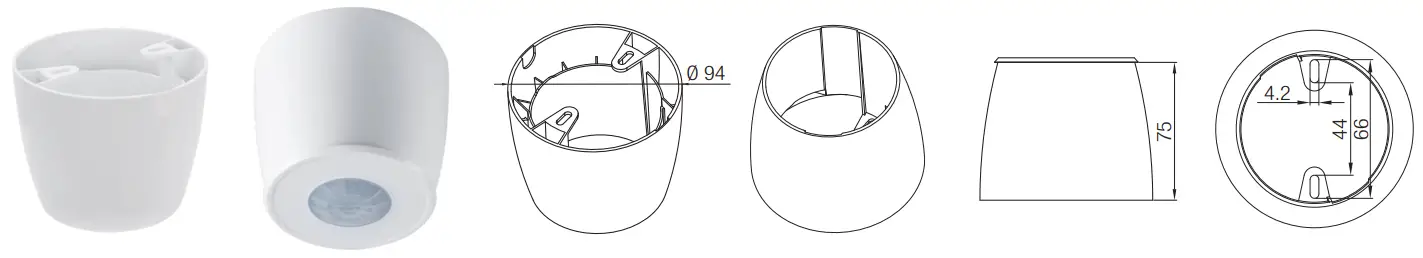
Installation
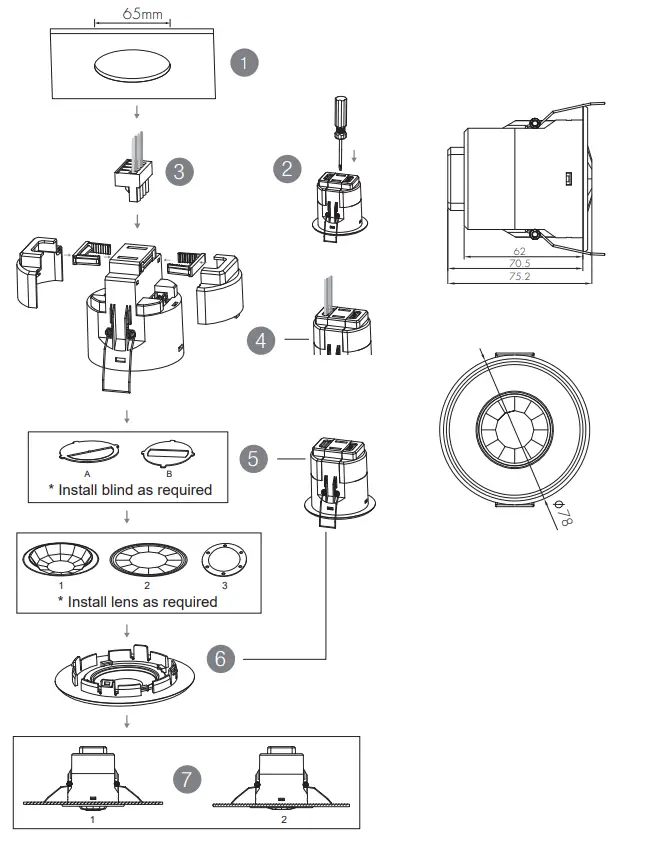
- Ceiling (drill hole 65mm)
- Carefully prise off the cable clamps.
- Make connections to the pluggable terminal blocks.
- Insert plug connectors and secure using the provided cable clamps, then clip terminal covers to the base.
- Fit detection blind (if required) and desired lens.
- Clip fascia to body.
- Bend back springs and insert into ceiling.
Functions
3.1 Daylight Harvest (Daylight Regulating)
Daylight sensor measures the available surrounding natural light, calculates how much electrical light is needed to reach the total lux expected. The demand is given to the LED driver by DALI signal, so as to deliver the needed amount of electric light.
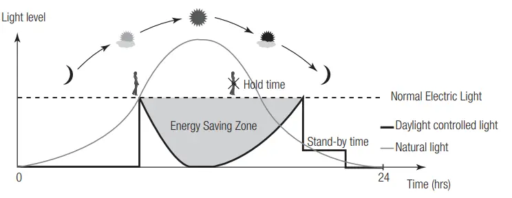
3.2 Lux Off Function
The built-in daylight sensor can measure ambient natural light and switch off the fixture automatically whenever artificial light is not required (natural light lux level exceeds daylight threshold).
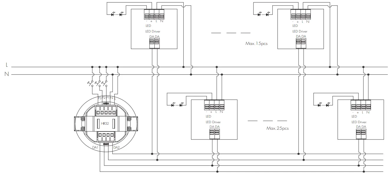
3.3 Dual DALI Output Control
Two channels of self-powered DALI output are available on HIR32 for connection of two groups of LED drivers. Please note that both channels share the same control settings sent from the occupancy sensor and photocell.
| System Capacity | DALI channel | DALI Driver < 2mA |
| HIR32 includes 2 channels total 80mA max. DALI PSU | DALI PSU Channel 1 (max 50mA) | 25 pcs |
| DALI PSU Channel 2 (max 30mA) | 15 pcs |
3.4 Manual Override (Push Function)
Three push terminals (P1, P2, P3) are available on the HIR32 for end-users to switch on/off, change the light brightness, colour temperature of the two DALI channels temporarily. The settings will revert to daylight harvest mode after sensor time-out.
* Long push on P1: adjust the hold-time light brightness of DALI channel 1; Short push (<1s) on P1: on/off function
* Long push on P2: adjust the hold-time light brightness of DALI channel 2; Short push (<1s) on P2: on/off function
* Long push on P3: cycles through colour tuning on both channels. (work with DT8 LED driver only) Short push (<1s) on P3: resume automatic daylight harvest mode .
Wire Preparation
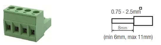
Pluggable screw terminal. It is recommended to make connections to the terminal before fitting to the sensor.
- 200 metres (total) max. for 1mm² CSA (Ta = 50℃)
- 300 metres (total) max. for 1.5mm² CSA (Ta = 50℃)
Wiring Diagram
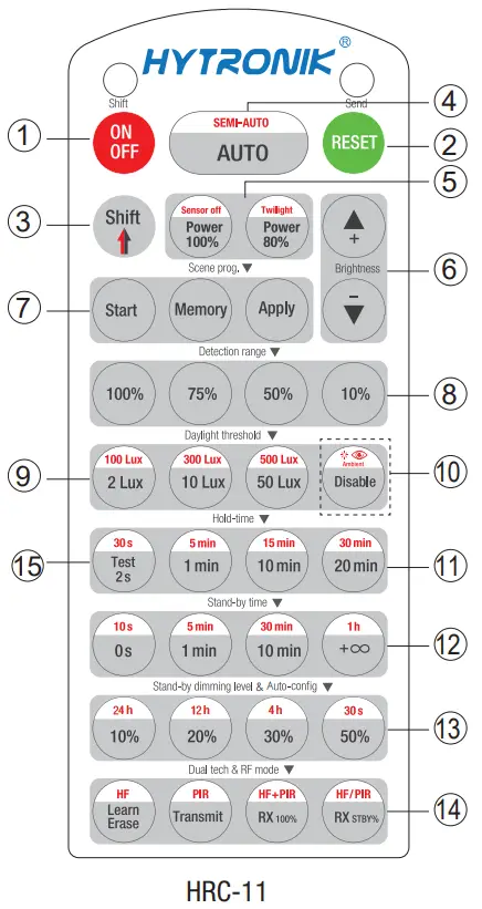
Permanent ON/OFF [ button 1]
Press button 1, to select permanent ON or permanent OFF mode.
* Press button 2/4 to to quit this mode.
RESET[ button 2]
Press button 2, all settings go back to default values as below:
Hold-time 5min, Daylight sensor 100Lux, Stand-by time: 10min, Stand-by dimming level: 20%
Test Mode[ button15 ]
This button is for testing purpose only. The sensor goes to test mode (hold-time is 2s) after commissoning, meanwhile the stand-by period and daylight sensor are disabled.
* This mode can be ended by pressing “reset”, or any button of “scene mode” and “hold-time”. The sensor settings are changed accordingly.
Shift [ button3 ]
Press button 3, the LED on the top left corner is on to indicate mode selection.
All values / settings in RED are in valid for 20 seconds.
Auto Mode [ button 4]
Press button 4 to initiate automatic mode. The sensor starts working and all settings remain as before the light is switched ON/OFF.
Semi-auto Mode [ button 3 & 4]
- Press button 3 Shift (the red LED is on for indication).
- Press button 4 to initiate semi-auto mode. The fixture is manually on by push-switch and automatically off in semi-auto mode.
Power output [ button 5]
5Press button 5, the light output shifts between 80% and 100%.
Note: the function of “Sensor off” and “Twilight” are disabled.
Brightness +/- [ button 6]
Press button 6 to adjust the light brightness and color temperature between 10%~100%.
Scene prog. [ zone 7 ] (One-key-commissioning)
- Press button “Start” to program.
- Select the buttons in 8“Detection range”,9/10“Daylight threshold”,11 “Hold time”12,“Stand-by time”13,“Stand-by dimming level” to set all parameters.
- Press button 7 “Memory” to save all the settings programmed in the remote control.
- Press button 7 “Apply” to set the settings to each sensor unit(s).
For example, to set detection range 100%, daylight threshold
Disable, hold time 5min, stand-by time +∞, stand-by dimming level 30%, steps should be:
Press button 7 Start, button 8 100%,10 Disable, Shift, 11 5min, 3 Shift, 12+∞ 13, 30%,7 Memory. By pointing to the sensor unit(s) and pressing 7Apply, all settings are passed on the sensor(s).
Detection range [ zone 8]
These two buttons are disabled.
Daylight threshold [ zone 9]
Press buttons in zone to set daylight sensor at 2Lux/ 10Lux /50Lux / 100Lux / 300Lux / 500Lux / Disable.
Note: To set daylight sensor at 100Lux / 300Lux / 500Lux, press 3 Shift button first.
Ambient daylight threshold [ button 10]
- Press button 3 Shift, the red LED starts to flash.
- Press button 10, the ambient lux level is sampled and set as the new daylight threshold / target Lux level.
Hold time [ zone 11]
Press buttons in zone 11 to set the hold time at 2s / 30s / 1min /5min / 10min / 15min / 20min / 30min.
Note:
- To set hold-time at 30s / 5min / 15min / 30min, press button 3 Shift at first.
- 2s is for test purpose only, stand-by period and daylight sensor settings are disabled in this mode.
*To exit from Test mode, press button 2 or any button in zone 11.
Stand-by time [ zone 12]
Press buttons in zone 12 to set the stand-by period at 0s / 10s /1min / 5min / 10min / 30min / 1h / +∞.
Note: “0s” means on/off control; “+∞” means bi-level control, 100% on when motion detected, and remains at the stand-by dimming level when no presence after hold-time.
Stand-by dimming level [ zone 13]
Press buttons in zone 13 to set the stand-by dimming level at 10% /20% / 30% / 50%.
Note: the function of 24h/12h/4h/30s are disabled.
Dual tech & RF mode [ zone14 ]
All buttons in zone 14 are disabled.
Detection Pattern & Optional Accessories
1. HIR32 (Low-bay)

HIR32: Low-bay flat lens detection pattern for single person @ Ta = 20ºC
(Recommended ceiling mount installation height 2.5m-6m)
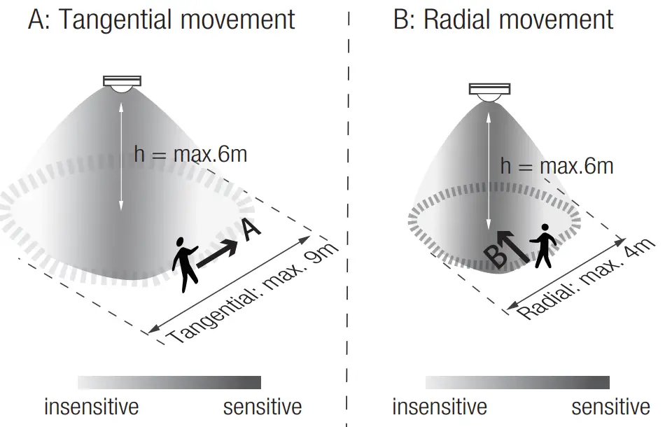
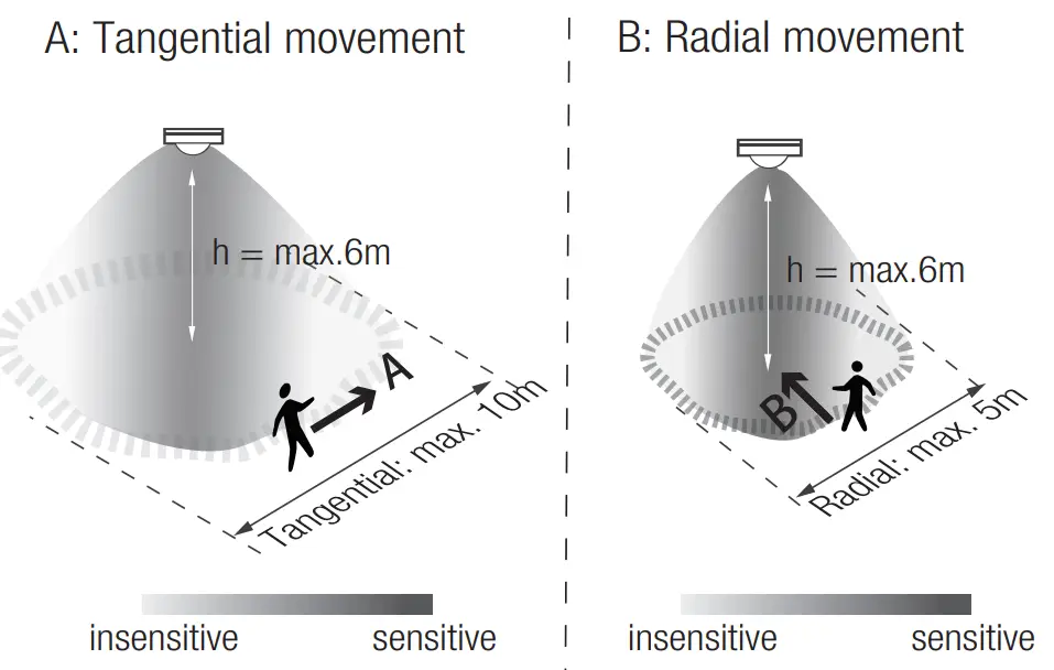
| Mount height | Tangential (A) | Radial (B) |
| 2.5m | max 50m²(Ø = 8m) | max 13m² (Ø = 4m) |
| 3m | max 64m² (Ø = 9m) | max 13m² (Ø = 4m) |
| 4m | max 38m² (Ø = 7m) | max 13m²(Ø = 4m) |
| 5m | max 38m² (Ø = 7m) | max 13m² (Ø = 4m) |
| 6m | max 38m² (Ø = 7m) | max 13m² (Ø = 4m) |
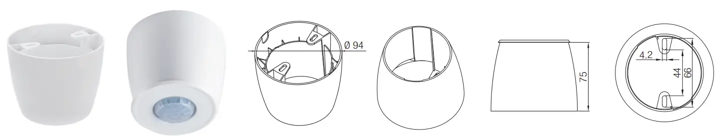
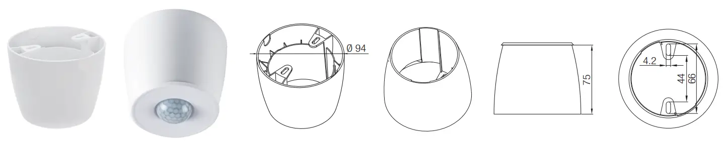
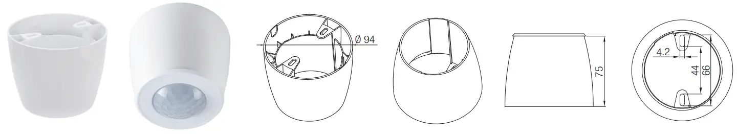
Optional Accessory — Ceiling/Surface Mount Box: HA03
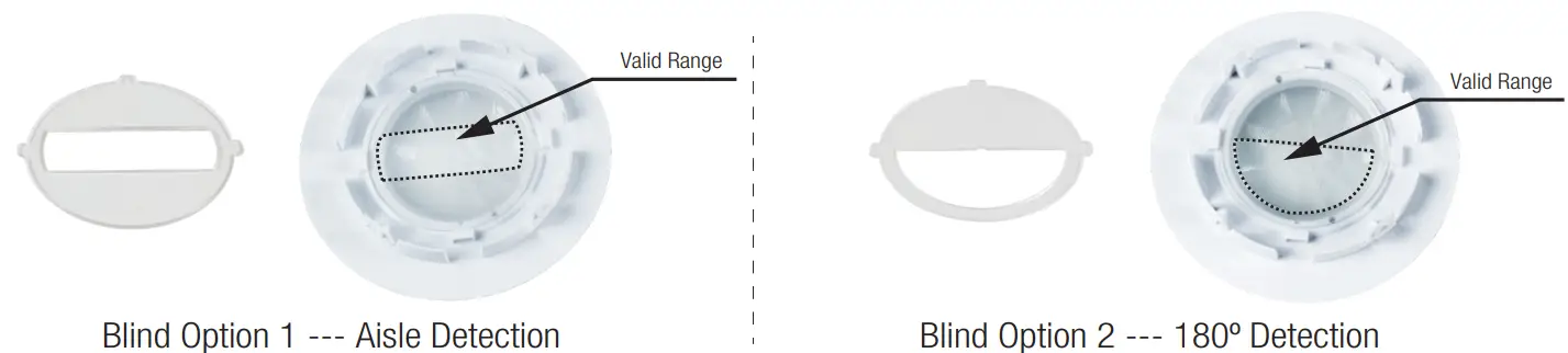
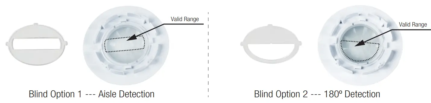
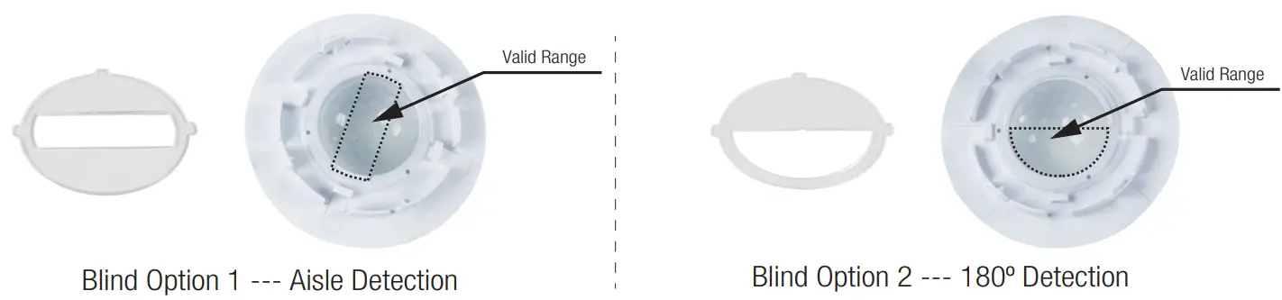
Optional Accessory — Blind Insert for Blocking Certain Detection Angles
2. HIR32/R (Reinforced Low-bay)
HIR32/R: Low-bay convex lens detection pattern for single person @ Ta = 20ºC
(Recommended ceiling mount installation height 2.5m-6m)
| Mount height | Tangential (A) | Radial (B) |
| 2.5m | max 79m² (Ø = 10m) | max 20m² (Ø = 5m) |
| 3m | max 79m² (Ø = 10m) | max 20m² (Ø = 5m) |
| 4m | max 64m² (Ø = 9m) | max 20m² (Ø = 5m) |
| 5m | max 50m² (Ø = 8m) | max 20m² (Ø = 5m) |
| 6m | max 50m² (Ø = 8m) | max 20m² (Ø = 5m) |
Optional Accessory — Ceiling/Surface Mount Box: HA03
Optional Accessory — Blind Insert for Blocking Certain Detection Angles
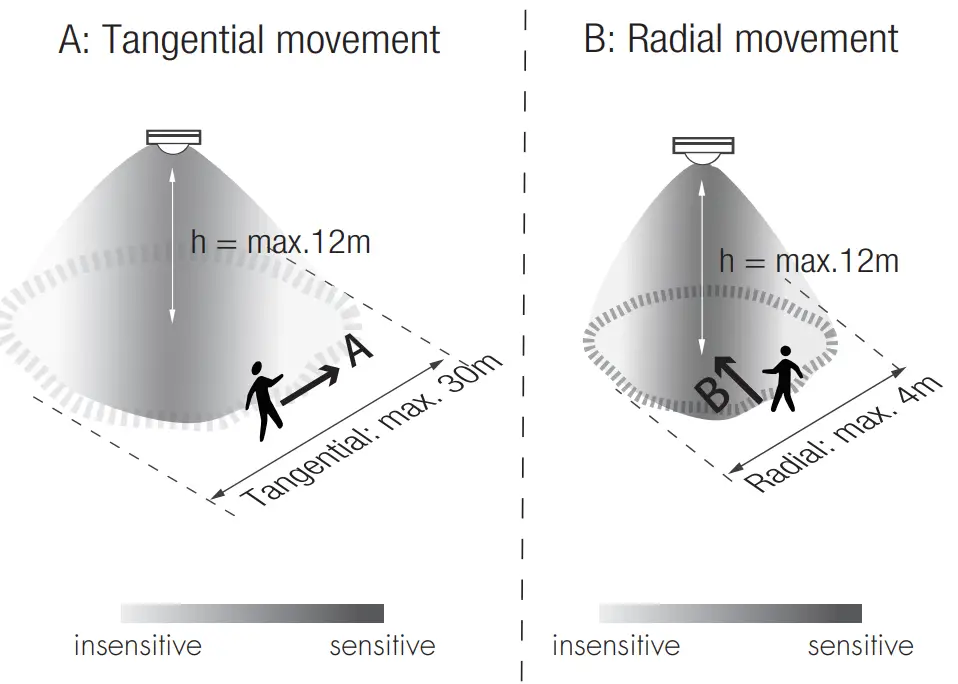
3. HIR32/H (High-bay)
HIR32/H: High-bay lens detection pattern for forklift @ Ta = 20ºC
(Recommended ceiling mount installation height 10m-15m)
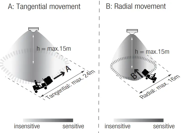
| Mount height | Tangential (A) | Radial (B) |
| 10m | max 380m² (Ø = 22m) | max 201m² (Ø = 16m) |
| 11m | max 452m² (Ø = 24m) | max 201m² (Ø = 16m) |
| 12m | max 452m² (Ø = 24m) | max 201m² (Ø = 16m) |
| 13m | max 452m² (Ø = 24m) | max 177m² (Ø = 15m) |
| 14m | max 452m² (Ø = 24m) | max 133m² (Ø = 13m) |
| 15m | max 452m² (Ø = 24m) | max 113m² (Ø = 12m) |
HIR32/H: High-bay lens detection pattern for single person @ Ta = 20ºC
(Recommended ceiling mount installation height 2.5m-12m)
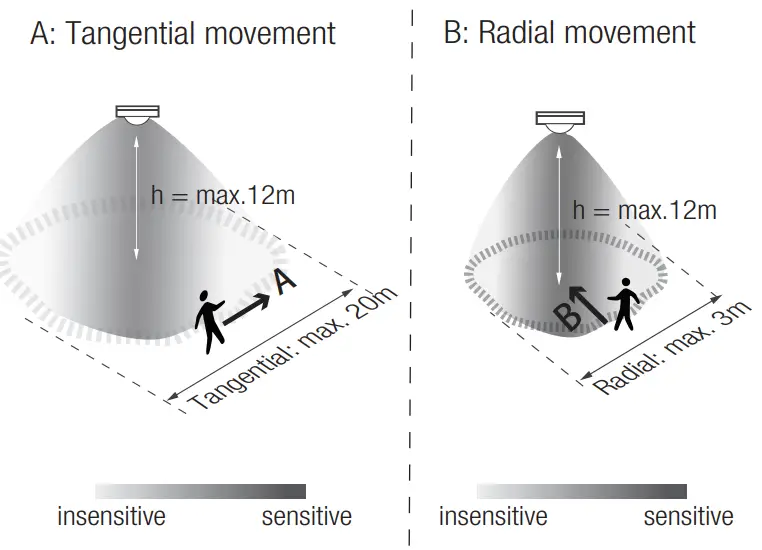
| Mount height | Tangential (A) | Radial (B) |
| 2.5m | max 50m² (Ø = 8m) | max 7m² (Ø = 3m) |
| 6m | max 104m² (Ø = 11.5m) | max 7m² (Ø = 3m) |
| 8m | max 154m² (Ø = 14m) | max 7m² (Ø = 3m) |
| 10m | max 227m² (Ø = 17m) | max 7m² (Ø = 3m) |
| 11m | max 269m² (Ø = 18.5m) | max 7m² (Ø = 3m) |
| 12m | max 314m² (Ø = 20m) | max 7m² (Ø = 3m) |
Optional Accessory — Ceiling/Surface Mount Box: HA03
Optional Accessory — Blind Insert for Blocking Certain Detection Angles
4. HIR32/RH (Reinforced High-bay with 3-Pyro)
HIR32/RH: Reinforced high-bay lens detection pattern for forklift @ Ta = 20ºC
(Recommended ceiling mount installation height 10m-15m)
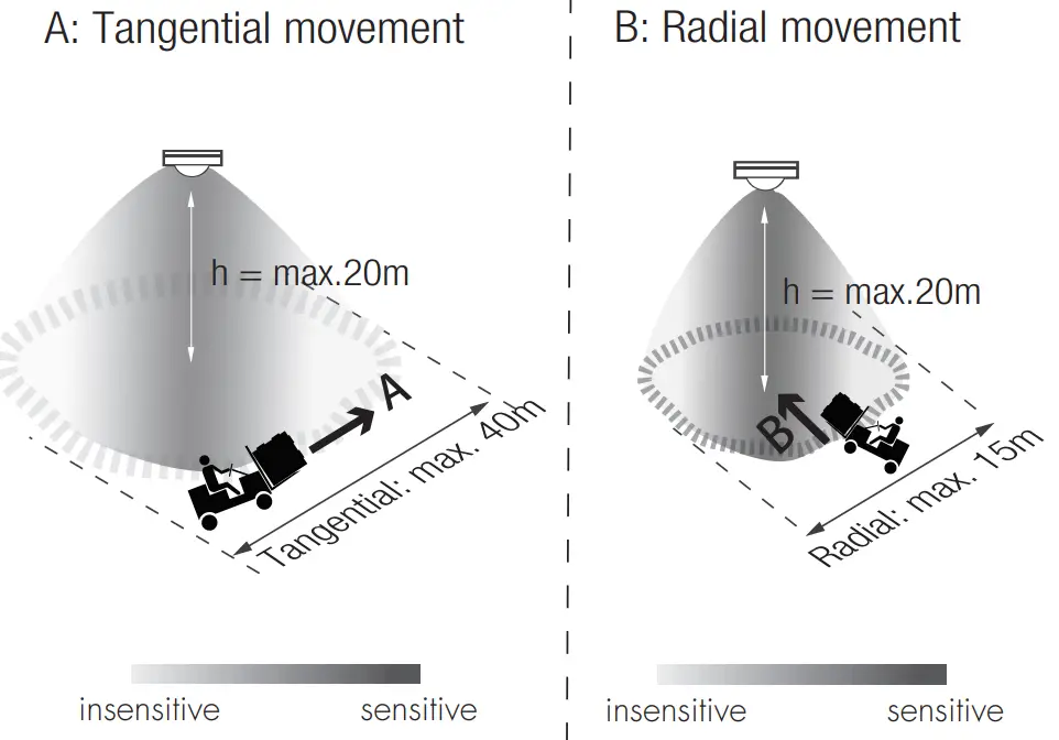
| Mount height | Tangential (A) | Radial (B) |
| 10m | max 346m² (Ø = 21m) | max 177m² (Ø = 15m) |
| 11m | max 660m² (Ø = 29m) | max 177m² (Ø = 15m) |
| 12m | max 907m² (Ø = 34m) | max 154m² (Ø = 14m) |
| 13m | max 962m² (Ø = 35m) | max 154m² (Ø = 14m) |
| 14m | max 1075m² (Ø = 37m) | max 113m² (Ø = 12m) |
| 15m | max 1256m 2 (Ø = 40m) | max 113m 2 (Ø = 12m) |
| 20m | max 707m² (Ø = 30m) | max 113m² (Ø = 12m) |
HIR32/RH: Reinforced high-bay lens detection pattern for single person @ Ta = 20OC
(Recommended ceiling mount installation height 2.5m-12m)
| Mount height | Tangential (A) | Radial (B) |
| 2.5m | max 38m² Ø = 7m) | max 7m² (Ø = 3m) |
| 6m | max 154m² (Ø = 14m) | max 7m² (Ø = 3m) |
| 8m | max 314m²(Ø = 20m) | max 7m² (Ø = 3m) |
| 10m | max 531m² (Ø = 26m) | max 13m² (Ø = 4m) |
| 11m | max 615m² (Ø = 28m) | max 13m² (Ø = 4m) |
| 12m | max 707m² (Ø = 30m) | max 13m² (Ø = 4m) |
Optional Accessory — Ceiling/Surface Mount Box: HA03
Additional Information / Documents
- Regarding precautions for PIR sensor installation and operation, please kindly refer to www.hytronik.com/download>knowledge>PIRSensors – Precautions for Product Installation and Operation
- Regarding Hytronik standard guarantee policy, please refer to www.hytronik.com/download>knowledge>Hytronik Standard Guarantee Policy
![]() HIR32-20210813-A0
HIR32-20210813-A0
www.HYTRONIK.COM


