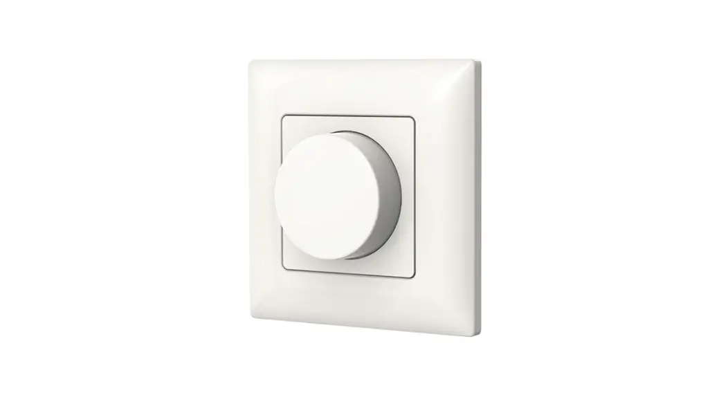
![]() Wall Mounted Scene or Switch Panel
Wall Mounted Scene or Switch Panel
Model No.: PK8, PK4
Push button/2-8 Scene/2-8 Zone dimming/Dual color LED key/AC input/RF 2.4G and DMX 512 signal output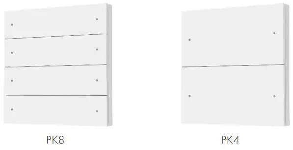
![]()
PK8 and PK4 are designed for scene control, with 8/6/4/2 scene memories selectable, and each scene is programmed by 8 zone and 8 scene RF remote RS10.
Features
- 8/4 key panel RF 2.4G remote with scene recall or zone dimming function, selectable by DIP switch.
- Each zone can remote control one or multiple RF 2.4G 1-5 colors LED controllers.
- Can also be used as an 8/4/2 zone dimming DMX512 master.
- DMX signal output complies with standard DMX512 protocol, compatible with DMX decoder from any supplier.
- Each push button with blue and red dual-color LED indicator.
- White & Black & Golden color panels are available.
Technical Parameters
Input and Output
| Input voltage | 100-240VAC |
| Input current | Max 0.1A |
| Output signal | RF 2.4GHz, DMX512 |
Dimming data
| Input signal | Push button + RF 2.4GHz |
| RF Control distance | 10m(Barrier-free space) |
| Dimming level | 256 levels |
| Dimming range | 0 -100% |
Warranty
| Warranty | 5 years |
Safety and EMC
| EMC standard (EMC) | ETSI EN 301 489-1 V2.2.3 ETSI EN 301 489-17 V3.2.4 |
| Safety standard(LVD) | EN 62368-1:2020+A11:2020 |
| Radio Equipment(RED) | ETSI EN 300 328 V2.2.2 |
| Certification | CE,EMC,LVD,RED |
Environment
| Operation temperature | Ta: -30°C ~ +55°C |
| Case temperature (Max.) | T c: +65°C |
| IP rating | IP20 |
Mechanical Structures and Installations
Installation diagram:
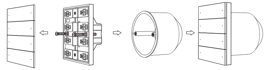 | |||
| Uninstall button | Turn the screw | Base | Install the button |
Typical base as below:
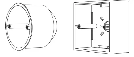 | |
| European style | 86 size |
Key function
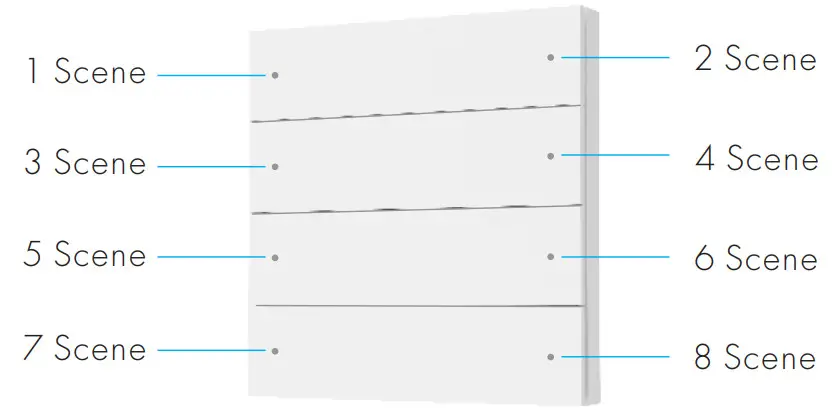
PK8 Scene & Switch Panel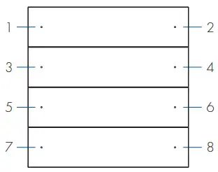
8 Scene![]() 1: Scene 1 2: Scene 2 3: Scene 3 4: Scene 4
1: Scene 1 2: Scene 2 3: Scene 3 4: Scene 4
5: Scene 5 6: Scene 6 7: Scene 7 8: Scene 8
1-8 Short press: Recall scene 1-8.
1-8 Long press(2s): Turn off this scene when it is on.
ON,OFF,6 Scene![]() 1: ON 2: OFF 3: Scene 1 4: Scene 2
1: ON 2: OFF 3: Scene 1 4: Scene 2
5: Scene 3 6: Scene 4 7: Scene 5 8: Scene 6
1 Short press: Turn on the scene light.
1 Long press(1-6s): Dimming up when light is on.
2 Short press: Turn off the scene light.
2 Long press(1-6s): Dimming down when light is on.
3-8 Short press: Recall scenes 1-6.
8 Zone ON/OFF![]() 1: Zone 1 on/off 2: Zone 2 on/off 3: Zone 3 on/off 4: Zone 4 on/off
1: Zone 1 on/off 2: Zone 2 on/off 3: Zone 3 on/off 4: Zone 4 on/off
5: Zone 5 on/off 6: Zone 6 on/off 7: Zone 7 on/off 8: Zone 8 on/off
1-8 Short press: Turn on or off the light of each zone.
1-8 Long press(1-6s): Dimming up or down when light is on.
4 Zone ON, OFF![]() 1: Zone 1 on 2: Zone 1 of 3: Zone 2 on 4: Zone 2 off
1: Zone 1 on 2: Zone 1 of 3: Zone 2 on 4: Zone 2 off
5: Zone 3 on 6: Zone 3 of 7: Zone 4 on 8: Zone 3 off
1,3,5,7 Short press: Turn on the light of each zone.
1,3,5,7 Long press(1-6s): Dimming up when light is on.
2,4,6,8 Short press: Turn off the light of each zone.
2,4,6,8 Long press(1-6s): Dimming down when light is on.
PK4 Scene & Switch Panel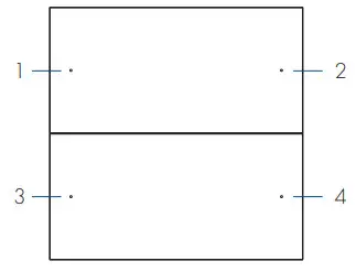
4 Scene![]() 1: Scene 1 2: Scene 23: Scene 3 4: Scene 4
1: Scene 1 2: Scene 23: Scene 3 4: Scene 4
1-4 Short press: Recall scenes 1-4.
1-4 Long press(2s): Turn off this scene when it is on.
ON,OFF,2 Scene![]() 1: ON 2: OFF
1: ON 2: OFF
3: Scene 1 4: Scene2
1 Short press: Turn on the light.
1 Long press(1-6s): Dimming up when light is on.
2 Short press: Turn off the light.
2 Long press(1-6s): Dimming down when light is on.
3,4 Short press: Recall scenes 1-2.
4 Zone ON/OFF![]() 1: Zone 1 on/off 2: Zone 2 on/off
1: Zone 1 on/off 2: Zone 2 on/off
3: Zone 3 on/off 4: Zone 4 on/off
1-4 Short press: Turn on or off the light of each zone.
1-4 Long press(1-6s): Dimming up or down when light is on.
2 Zone ON, OFF![]() 1: Zone 1 on 2: Zone 2 off
1: Zone 1 on 2: Zone 2 off
3: Zone 1 on 4: Zone 2 off
1,3 Short press: Turn on the light of each zone.
1,3 Long press(1-6s): Dimming up when light is on.
2,4 Short press: Turn off the light of each zone.
2,4 Long press(1-6s): Dimming down when light is on.
Scene programming
When the panel is set as 8/6/4/2 scene function, each scene must be programmed by RS10 remote firstly, then use the panel scene button to recall these scenes.
Step1: one or multiple light zone are matched with the RS10 remote.
Step2: use the RS10 remote to change the color, brightness, or on/off state of the light zone, and save the current state to 1-8 scenes.
Step3: one or multiple light zone are matched with the PK8 panel remote.
Step4: use the panel scene button to recall these scenes which are programmed by the RS10 remote.
The scene number of the scene panel corresponds to the scene number of the RS10 remote.
 PK8 with 8 scene
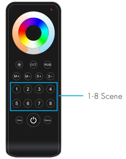 RS10 remote
Panel work as RF remote
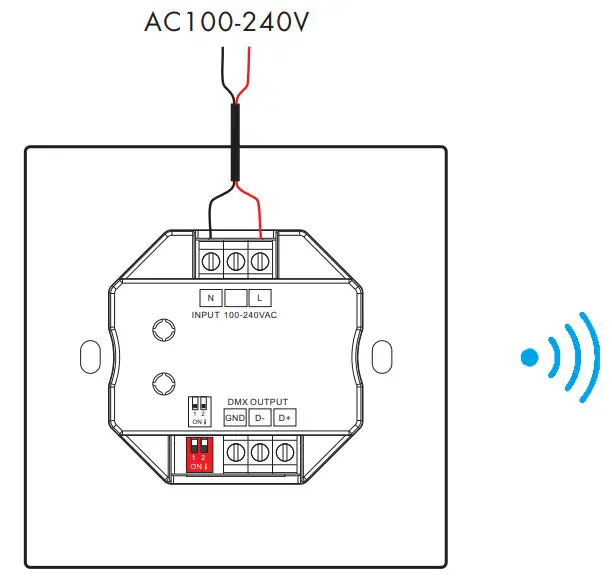
When the panel work as RF remote, it needs to match with other RF 2.4G 1-5 colors LED controllers.
The end user can choose the suitable match/delete ways. Two options are offered for selection:
Use the controller’s Match key
Match:
Short press the match key, and immediately press the Scene or ON/OFF key of the panel.
The LED indicator fast flash a few times means the match is successful.
Delete:
Press and hold the match key for 5s to delete all matches,
The LED indicator fast flash a few times means all matched remotes were deleted.
Use Power Restart
Match:
Switch off the power of the receiver, then switch on the power, and repeat again.
Immediately short press Scene or ON/OFF key 3 times on the panel.
The light blinks 3 times means the match is successful.
Delete:
Switch off the power of the receiver, then switch on power, and repeat again.
Immediately short press Scene or ON/OFF key 5 times on the panel.
The light blinks 5 times means all matched remotes were deleted.
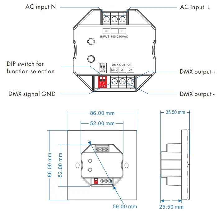
Wiring diagram for panel work as RF remote
 User Manual Ver 1.0.2
Recommended RF LED controller and driver
| Light type | Output type | Model | lickluencime | Product picture |
| Di MS | Constant voltage | VI | Single Co lot LED Controller 1536V, BA I | |
| VI-l | Single Color LED Controller ( I 248V, 15A1 | |||
| V1-H/P | Single Color LED Controller t 12-24V. BA I | |||
| Canna& current | MOM | Rf Constant Current LED Driver ( IOW, 100.450mA I | ||
| PT.I 2A.I | RF Constant Current LED Driver I 12W, 100-450mA I | |||
| PB.12A1 | RE ConstantCurrent LED Driver ( 12W. 100-450mA I | |||
| CXR-2 IA | Rf Constant Current LED Driver t 1.5-21W, 150-500mA I | |||
| CCT | Constant voltage | 112 | Dual Color LE D Controler i 12.24V. 5A/CH I | |
| V24 | Duol Color LEDControler ( 12.48V. 8A/CH I | |||
| Constant Current | PT-I 2A-2 | RF Constant Current LED CCT Driver t 12W. 150-500mA I | ||
| PT-20A•2 | RE ConstantCurrent LED CCT Driver I 20VV, 300-1050mA I | |||
| CXR-21A-2tWe1 | Bluetooth &RE 2CH Constant Current (ED Driver t 2IW, 1 50-500mA 1 | |||
| CXR.2 I A.2ONTI | WiFi &RF 2CHConssont Current LED Driver t 2 IW, 1 50-500mA I | |||
| ;CP PGBW | Constant voltage | V3 | 3 Channel (ED RE Controller ( 12•24V, 4A/CH I | |
| V31 | 3 Channel LED RE Controller t 1 NEW, 6A/CH I | |||
| VP | 4 Channel (ED RE Co moist ( 12-24V, 4A/CH I | |||
| V4 | 4 Channel LED REContro/ler ( I 2-48V, 5A/C H I | |||
| Constant | C4 | 4 Channel LED RE Co mole, t 1 24 BY, 350-1200mA I | ||
| RGB+CCT | Constant voltage | V5414 | 5-Channel LED RF Controller ( 12.24V. 3A/CH I | |
| V.51 | 5 Channel LED RE Controller ( 12-48V. 5A/CH I |
Panel work as DMX512 Master
When the panel is set as an 8/4/2 zone dimming function, it can also work as DMX512 master.
After connecting with DMX decoders, please set the DMX decoder’s address as below:
DMX decoder’s address 001 is controlled by Zone 1,
DMX decoder’s address 002 is controlled by Zone 2,
DMX decoder’s address 003 is controlled by Zone 3,
DMX decoder’s address 004 is controlled by Zone 4,
DMX decoder’s address 005 is controlled by Zone 5,
DMX decoder’s address 006 is controlled by Zone 6,
DMX decoder’s address 007 is controlled by Zone 7,
DMX decoder’s address 008 is controlled by Zone 8.
Wiring diagram for panel work as DMX512 master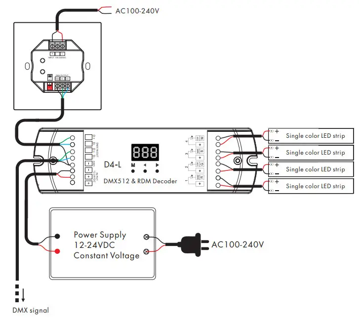


 Wall Mounted Touch Panel User Manual")


 Rotary Glass Panel Rf Remote Controller User Manual")

