![]() MTN647393 Space logic KNX Switch actuator REG-K/2×230/16 with manual mode
MTN647393 Space logic KNX Switch actuator REG-K/2×230/16 with manual mode
Instruction Manual SpaceLogic KNX
Switch actuator REG-K/2×230/16 with manual mode
Art. no. MTN647393
Operating instructions
For your safety
![]()
![]() DANGER
DANGER
HAZARD OF ELECTRIC SHOCK, EXPLOSION, OR ARC FLASH
The safe electrical installation must be carried out only by skilled professionals. Skilled professionals must prove profound knowledge in the following areas:
- Connecting to installation networks
- Connecting several electrical devices
- Laying electric cables
- Connecting and establishing KNX networks
- Safety standards, local wiring rules, and regulations
Failure to follow these instructions will result in death or serious injury.![]()
![]() DANGER
DANGER
RISK OF FATAL INJURY FROM ELECTRIC SHOCK
The output may carry an electrical current even when the load is switched off.
- When working on the device: Always disconnect the device from the supply by means of the fuse in the incoming circuit.
- Even if the manual switch is in the „OFF“ position, a KNX telegram can switch the connections to being live at any time. Before working on the device, always diconnect the fuse in the incoming circuit from the supply.
Failure to follow these instructions will result in death or serious injury.
![]() CAUTION
CAUTION
The device may be damaged!
• Always operate the product in compliance with the specified technical data.
• Only install devices with at least basic insulation next to the device.
Failure to follow these instructions can result in equipment damage.
Getting to know the actuator
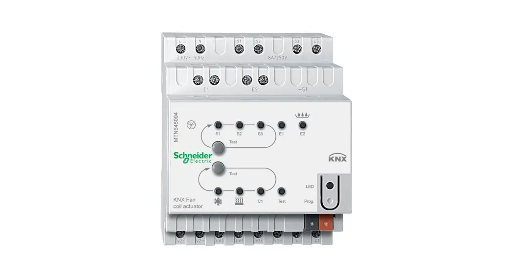
The switch actuator REG-K/2×230/16 with manual mode (referred to below as the actuator) can switch two loads via separate, floating make contacts.
You can also manually switch the connected loads with manual switches on the actuator without bus voltage.
The actuator has a bus coupler. It is installed on a DIN rail TH 35 according to EN 60715, with the bus connection made via a bus connecting terminal. It is supplied with
power from the bus voltage. A data rail is not required.
Connections, displays, and operating elements
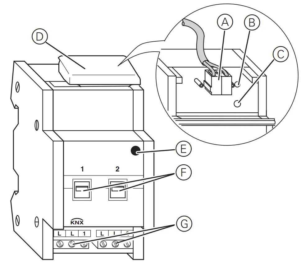
A Bus connection terminal, max. 4 core pairs
B Programming LED (red)
C Programming button
D Cable cover
E Operating LED „RUN“ (green)
F Manual switch
G Screw terminals
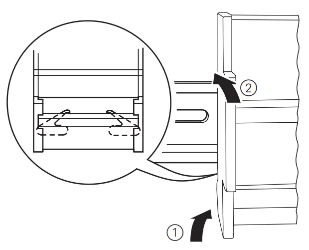
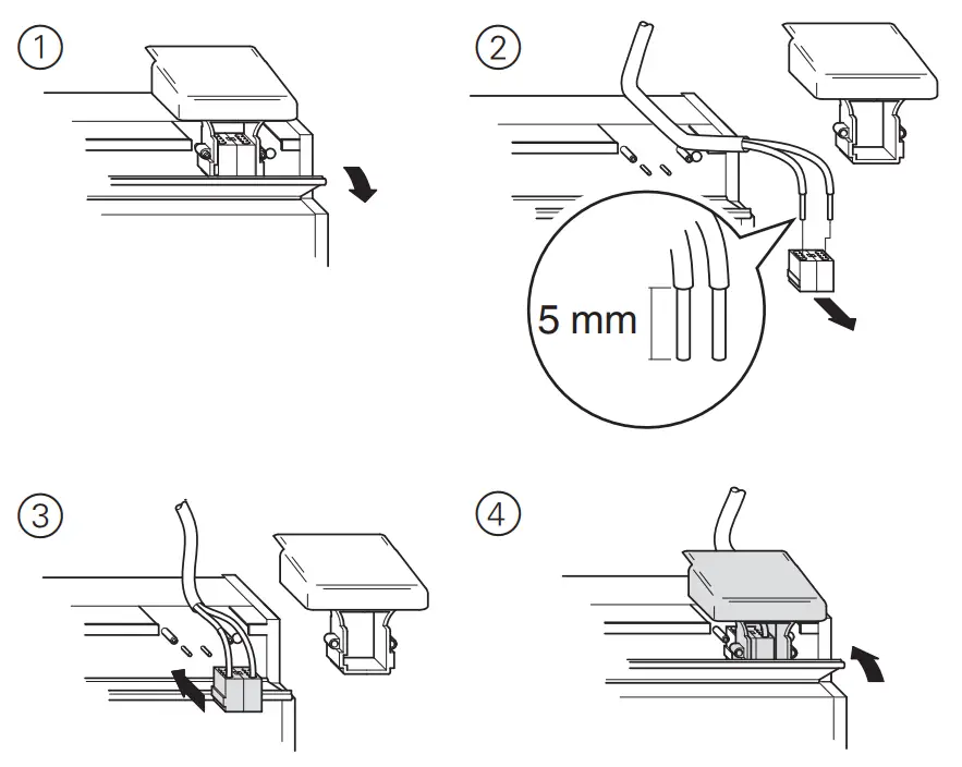
Mounting the actuator
- Set the actuator onto the DIN rail.

- Connect KNX.
![]() WARNING Risk of death from electric shock. The device can become damaged. Safety clearance must be guaranteed in accordance with IEC 60664–1. There must be at least 4 mm between the individual cores of the 230 V supply cable and the KNX line A.
WARNING Risk of death from electric shock. The device can become damaged. Safety clearance must be guaranteed in accordance with IEC 60664–1. There must be at least 4 mm between the individual cores of the 230 V supply cable and the KNX line A.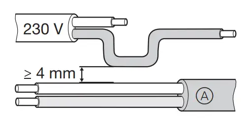
![]()
![]() DANGER
DANGER
RISK OF FATAL INJURY FROM ELECTRIC SHOCK
Voltage may be present at the outputs when the main voltage is connected to the system.
If subjected to strong vibrations during transportation, the switch contacts might change to the enabled state. After connecting the bus voltage, set the relays of the channels to the position desired simply by switching „On/Off“ or by changing the manual switch to „OFF“.
Failure to follow these instructions will result in death or serious injury.![]() CAUTION ‘
CAUTION ‘
The device may be damaged!
• Protect the switch contacts with a series-connected 16 A circuit breaker.
Failure to follow these instructions can result in equipment damage.
3. Connect the bus voltage.
4. Wait at least 30 seconds.
5. Switch the relays of the channels on and off manually once with the manual switches.
6. Connect the load.
The cables to the loads as well as the system voltages (L1, L2 or L3) are connected via screw terminals for max. 16 A. Every two L connections are bridged internally.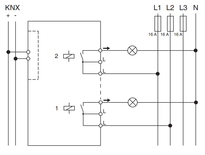 7. Connect the mains voltage.
V6473-561-02 11/21
Now you can check the functionality of the actuator and the connected loads without having to load the application from the ETS (See the section “Operating the actuator”).
Putting the actuator into operation
- Press the programming button. The programming-LED lights up.
- Load the physical address and application into the device from the ETS.
The programming LED goes out.
The operation LED lights up: The application was loaded successfully, the device is ready for operation.
Operating the actuator
Normally, you control connected devices using pushbuttons or by remote control. However, you can manually switch each of the actuator‘s channels on and off directly at the
manual switches.
Technical data
| External auxiliary voltage: | None |
| Power supply from bus: | DC 24 V / max. 10 mA |
| Insulation voltage: | AC 4 kV between bus/mains voltage |
| Switch contact: | 2 x make contact, floating |
| Nominal voltage: | AC 100–240 V ±10% |
| Connected load Incandescent lamps | 1600 W at AC 100 V 3600 W at AC 230 V 3840 W at AC 240 V with 10,000 switching cycles |
| Halogen lamps: | 1086 VA at AC 100 V 2500 VA at AC 230 V 2608 VA at AC 240 V parallel compensated with 5,000 switching cycles |
| Fluorescent lamps: | 1086 VA at AC 100 V 2500 VA at AC 230 V 2608 VA at AC 240 V parallel compensated with 5,000 switching cycles |
| Capacitive load: | 16 A, 200 µF at AC 100 V 16 A, 200 µF at AC 230 V 16 A, 200 µF at AC 240 V with 5,000 switching cycles |
| Fuse: | The switch contact must be protected by 16 A series-connected circuit breaker. |
| Switching frequency: | max. 10 per minute at nominal load |
| Ambient temperature: | |
| Operation: | -5 °C to +45 °C |
| Max. humidity: | 93 %, no moisture condensation |
| Environment: | can be used at up to 2000 m above sea level (MSL) |
| Operating elements | 1 programming button 2 manual switches |
| Display elements: | 1 red LED: programming check 1 green LED: ready for operation „RUN“ |
| Connections Bus: | via two 1 mm pins for bus connecting terminal |
| Outer conductor: | 2x 3-gang screw terminal for each max. 2.5 mm 2 |
| EC directives: | Low voltage directive 2006/95/ EC EMC-directive 2004/108/EC |
| Device width: | 2,5 modules = approx. 45 mm |
| Operation voltage: | min. AC 90 V – max. AC 265 V |
| Mains frequency: | 50–6 Hz ±10%0 |
| Nominal current: | 16 A, inductive load cosφ=0,6 |
![]() Schneider Electric -Contact
Schneider Electric -Contact
Schneider Electric Industries SAS
35 rue Joseph Monier
Rueil Malmaison 92500
France
If you have technical questions, please contact the Customer Care Centre in your country.
se.com/contact![]() UK Representative
UK Representative
Stafford Park 5
Schneider Electric Limited
Telford, TF3 3 BL, UK


