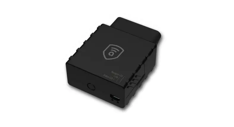
AIT250 Easy OBDII Tracker
![]()
![]()

![]()
![]()

![]()
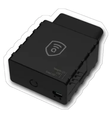
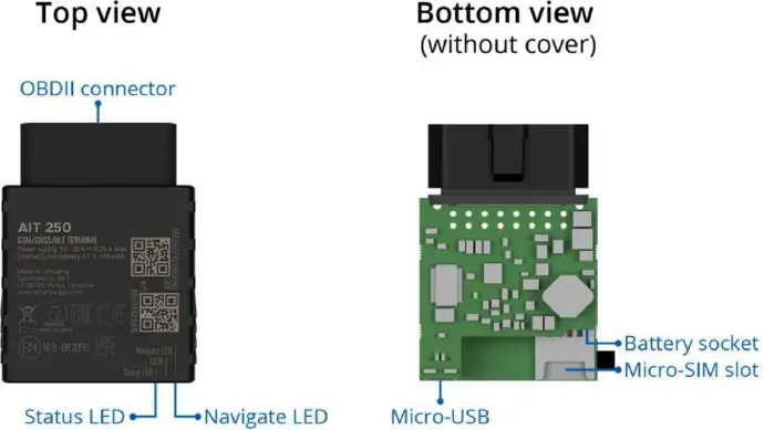
Know your device
Pinout
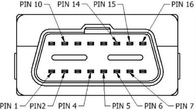
AIT 250 socket pinout
Pin number | Pin name | Description |
1 | DIN1 | Ignition input |
2 | PWM_BUS+/VPW | |
4 | GND (-) | Ground |
5 | GND (-) | Ground |
6 | CAN_H | CAN high |
7 | K-Line | |
10 | PWM_BUS | |
14 | CAN_L | CAN low |
15 | L-Line | |
16 | VCC (10 – 30)V DC(+) | Power supply (+10-30 V DC) |
AIT 250 socket pinout
Set up your device
How to insert Micro-SIM card and connect the battery
- Gently remove FMB001 cover using plastic pry tool from both sides.
- Insert Micro-SIM card as shown with PIN request disabled or read our Wiki how to enter it later in Amber Configurator. Make sure that Micro-SIM card cut-off corner is pointing forward to slot.
- Connect battery as shown to device. Position the battery in place where it does not obstruct other components.
- Attach device cover back.
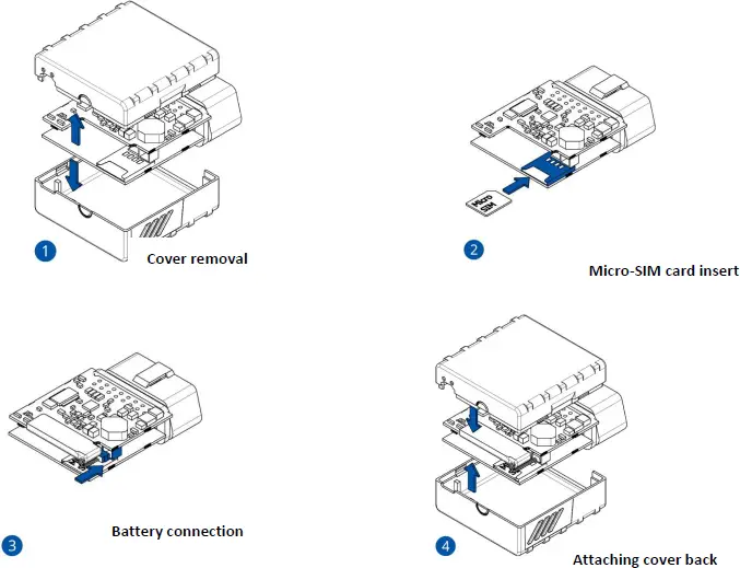
Device is ready to be Connected.
Micro-SIM card insert
Attaching cover back
LED indications
Navigation LED indications
Behaviour | Meaning |
Permanently switched on | GNSS signal is not received |
Blinking every second | Normal mode, GNSS is working |
Off | GNSS is turned off because: Device is not working or Device is in sleep mode |
Blinking fast constantly | Device firmware is being flashed |
Status LED indications
Behaviour | Meaning |
Blinking every second | Normal mode |
Blinking every two seconds | Sleep mode |
Blinking fast for a short time | Modem activity |
Off | Device is not working or Device is in boot mode |
Characteristics
Basic characteristics
Module | |
Name | AIT 250 |
Technology | GSM, GPRS, GNSS, BLUETOOTH |
GNSS | |
GNSS | GPS, GLONASS, GALILEO, BEIDOU, SBAS, QZSS, DGPS, AGPS |
Receiver | 33 channel |
Tracking sensitivity | -165 dBM |
Accuracy | < 3 m |
Hot start | < 1 s |
Warm start | < 25 s |
Cold start | < 35 s |
Cellular | |
GSM | GSM |
2G bands | Quad-band 850/900/1800/1900 MHz |
Data transfer | GPRS Multi-Slot Class 12 (up to 240 kbps), GPRS Mobile Station Class B |
Data support | SMS (text/data) |
Power | |
Input voltage range | 10 – 30 V DC with overvoltage protection |
Internal fuse | 3 A, 125 V |
Power consumption | At 12V < 5 mA (Ultra Deep Sleep) At 12V < 7 mA (Deep Sleep) At 12V < 7 mA (Online Deep Sleep) At 12V < 8 mA (GPS Sleep) At 12V < 28 mA (nominal with no load) At 12V < 0.25 A Max. (with full Load / peak) |
Bluetooth | |
Specification | 4.0 + LE |
Supported peripherals | Temperature and Humidity sensor, Headset, Inateck Barcode Scanner |
OBD INTERFACE | |
Data | K-Line, CAN Bus data |
Data reading | Up to 32 vehicle onboard parameters, 9 supported OBD protocols |
Interface | |
Digital Inputs | 1 |
Connection | OBDII socket |
GNSS antenna | Internal High Gain |
GSM antenna | Internal High Gain |
USB | 2.0 Micro-USB |
LED indication | 2 status LED lights |
SIM | Micro-SIM |
Memory | 128MB internal flash memory |
Physical specification | |
Dimensions | 50,7 x 49,6 x 25 mm (L x W x H) |
Weight | 63 g |
Operating environment | |
Operating temperature (without battery) | -40 °C to +85 °C |
Storage temperature (without battery) -40 °C to +85 °C | |
Operating humidity | 5% to 95% non-condensing |
Ingress Protection Rating | IP41 |
Battery charge temperature | 0 °C to +45 °C |
Battery discharge temperature | -20 °C to +60 °C |
Battery storage temperature | -20 °C to +45 °C for 1 month -20 °C to +35 °C for 6 months |
Features | |
Sensors | Accelerometer |
Scenarios | Green Driving, Over Speeding detection, Jamming detection, GNSS Fuel Counter, Excessive Idling detection, Unplug detection, Towing detection, Crash detection, Auto Geofence, Manual Geofence, Trip |
Sleep modes | GPS Sleep, Online Deep Sleep, Deep Sleep, Ultra Deep Sleep |
Configuration and firmware update | FOTA Web, FOTA, Amber Configurator (USB, Bluetooth), FMBT mobile application (Configuration) |
SMS | Configuration, Events,Debug |
GPRS commands | Configuration,Debug |
Time Synchronization | GPS, NITZ, NTP |
Fuel monitoring | OBDII |
Ignition detection | Digital Input 1, Accelerometer, External Power Voltage, Engine |
Safety information
This message contains information on how to operate AIT 250 safely. By following these requirements and recommendations, you will avoid dangerous situations. You must read these instructions carefully and follow them strictly before operating the device!
- The device uses SELV limited power source. The nominal voltage is +12 V DC. The allowed voltage range is +10…+30 V DC.
- To avoid mechanical damage, it is advised to transport the device in an impact-proof package. Before usage, the device should be placed so that its LED indicators are visible. They show the status of device operation.
- Before unmounting the device from vehicle, ignition MUST be OFF.
- All related devices must meet the requirements of EN 62368-1 standard.
Do not disassemble the device. If the device is damaged, the power supply cables are not isolated or the isolation is damaged, DO NOT touch the device before unplugging the power supply.
All wireless data transferring devices produce interference that may affect other devices which are placed nearby.
Please consult representatives of your vehicle model regarding OBDII location on your vehicle. In case you are not sure about proper connection, please consult qualified personnel.
The programming must be performed using a PC with autonomic power supply.
Installation and/or handling during a lightning storm is prohibited.
The device is susceptible to water and humidity.
Amber is not responsible for any harm caused by wrong cables used for connection between PC and AIT 250
WARNING! Do not use AIT 250 device if it distracts driver or causes inconvenience due to OBDII placement. Device must not interfere with driver.
Battery should not be disposed of with general household waste. Bring damaged or worn-out batteries to your local recycling center or dispose them to battery recycle bin found in stores.
Certification and Approvals
• AIT 250 ANATEL
• AIT 250 CE / RED
• AIT 250 E-Mark
• AIT 250 EAC
• AIT 250 RoHS
• AIT 250 REACH
• AIT 250 Declaration of IMEI assignment
• AIT 250 Declaration of device operation temperature
This sign on the package means that it is necessary to read the User‘s Manual before your start using the device. Full User‘s Manual version can be found in our
Wiki.
This sign on the package means that all used electronic and electric equipment should not be mixed with general household waste.
Hereby, Amber declare under our sole responsibility that the above described
product is in conformity with the relevant Community harmonization: European
Directive 2014/53/EU (RED).
Warranty
Amber connect guarantees its products to be free of any manufacturing defects for a period of 24 months. With additional agreement we can agree on a different warranty period, for more detailed information please contact our sales manager.
All batteries carry a reduced 6 month warranty period.
If a product should fail within this specific warranty time, the product can be:
- Repaired
- Replaced with a new product
- Replaced with an equivalent repaired product fulfilling the same functionality
- Amber can also repair products that are out of warranty at an agreed cost.
Warranty Disclaimer
Amber products are intended to be used by persons with training and experience. Any other use renders the limited warranties expressed herein and all implied warranties null and void and same are hereby excluded. also excluded from this limited warranty are any and all incidental or consequential damages including but not limited to, loss of use or revenue, loss of time, inconvenience or any other economic loss.


