![]() 2.4G RJ45 A WiFi 2.4G Adapter Instruction Manual
2.4G RJ45 A WiFi 2.4G Adapter Instruction Manual
EPEVER 2 4G RJ45 A WiFi 2 4G Adapter
※ Thanks for selecting the EPEVER WiFi transmission terminal;
please read this manual carefully before using the product.
※ Please keep this manual for future reference.
Overview
Through a local WiFi 2.4G network, the WiFi 2.4G adapter can transmit all operational data from the EPEVER solar controller, inverter, or inverter/charger to the EPEVER cloud server in real-time. Users can remotely monitor the connected devices and program parameters via the EPEVER server, mobile APP, or the large screen.
Features:
- Applicable to EPEVER controllers, inverters, or inverter/charger with RJ45, DB9 interfaces
- Use immediately after connecting, easy and convenient operation
- Directly powered by the communication port
- Up to 30 meters communication distance
- Support the “Local” and “EPEVER Cloud” working mode.
- One key to restore the factory settings
Appearance
2.1 EPEVER WiFi 2.4G RJ45 A
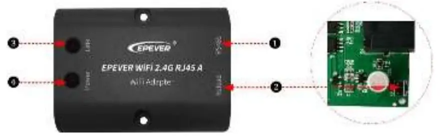
- Interface instruction
No. Name Instruction 1 RJ45 port Connect to the solar controller, inverter, or inverter/charger 2 Reload button One key to restore factory settings
Note: Long press the Reload button with a sharp object when the terminal’s power is on. The Link indicator flashes twice quickly, and the factory settings are restored successfully.3 Link indicator Indicate the communication status 4 Power indicator Indicate the power status - Indicator instruction
Indicator Status Instruction Link indicator ON solid in green Connect to the WiFi OFF Not connect to the WiFi Fast flashing in green Reset to the factory mode Power indicator ON solid in green Normal powered on OFF Not powered on
2.2 EPEVER WiFi 2.4G DB9 B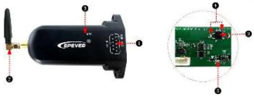
- Interface instruction
| No. | Name | Instruction |
| 1 | DB9 male connector* | Connect to the solar controller, inverter, or inverter/charger |
| 2 | Antenna | Enhance the signal transmission |
| 3 | Reset button | One key to restore factory settings Note: Long press the Reset button through the KEY hole with a sharp object when the terminal’s power is on. The indicator light flashes twice quickly, and the factory settings are restored. |
| 4 | Network Indicator | Indicate the communication status(observe the indicator status through the KEY hole) |
| 5 | Power Indicator | Indicate the power status |
* Connect the EPEVER WiFi 2.4G DB9 B to the solar controller, inverter, or inverter/charger by a DB-9 female connector. The wire sequence and name of the DB9 female connector are shown below.
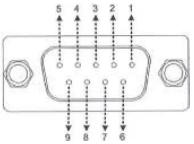
| No. | Name | Instruction | No. | Name | Instruction |
| 1 | NC | Floating | 6 | NC | Floating |
| 2 | NC | Floating | 7 | RS485-A | RS485-A |
| 3 | VCC2 | Power2 (12V/200mA) | 8 | RS485-B | RS485-B |
| 4 | GND2 | Power GND2 | 9 | VCC1 | Powerl (5V/400mA) |
| 5 | GND1 | Power GND1 |
Indicator instruction
| Indicator | Status | Instruction |
| Network Indicator | ON solid in green | Connect to the WiFi |
| OFF | Not connect to the WiFi | |
| Fast flashing in green | Reset to the factory mode | |
| Power Indicator | ON solid in green | Normal powered on |
| OFF | Not powered on |
3. System connection
Step1: Connect the WiFi transmission terminal to the controller, inverter, or inverter/charger through the RJ45 port or the DB9 connector. Take the connection diagram of the inverter/charger as an example as follows:
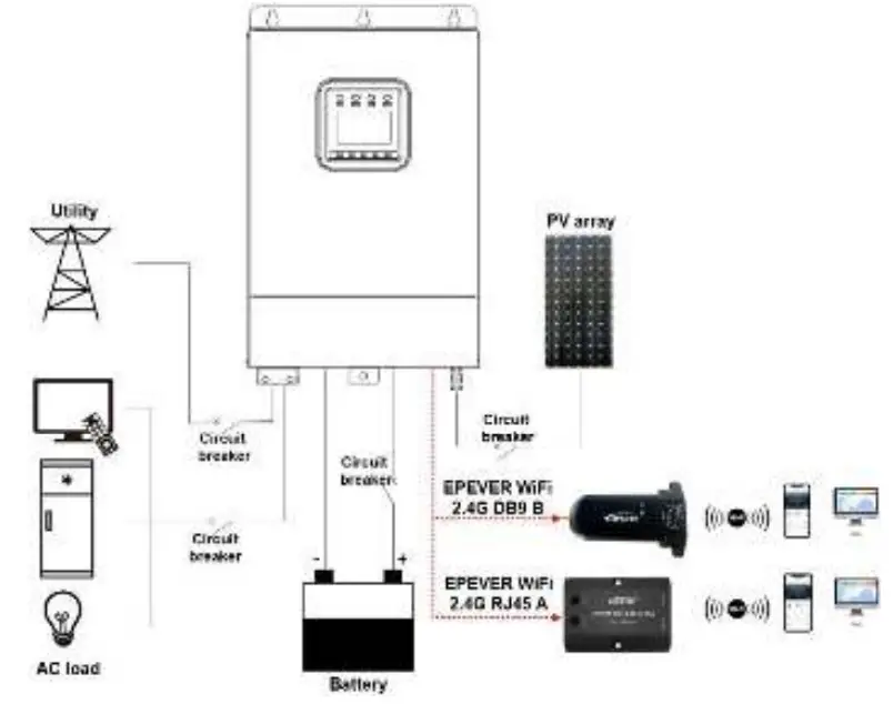
Note: EPEVER WiFi 2.4G RJ45 A is suitable for the controller, inverter, or inverter/charger designed with an RJ45 port. EPEVER WiFi 2.4G DB9 B is ideal for the device designed with a DB9 interface. For detailed connection cables, refer to the connected device’s accessories list.
Operations
After successfully connecting the WiFi terminal to the controller, inverter, or inverter/charger, the users remotely monitor the field devices through the PC, large screen, or mobile phone.
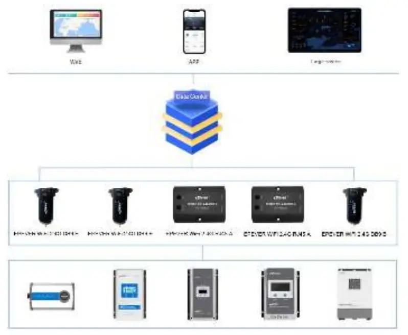
Take the APP as an example to introduce remote monitoring through the mobile phone.
Operation Steps:
Scenario 1: There is a local 2.4G WiFi network. The WiFi terminal can upload the collected data to the EPEVER cloud automatically.
Step1: Turn on the WiFi switch on the mobile phone, and connect to the local WiFi network (2.4G WiFi network is a must).
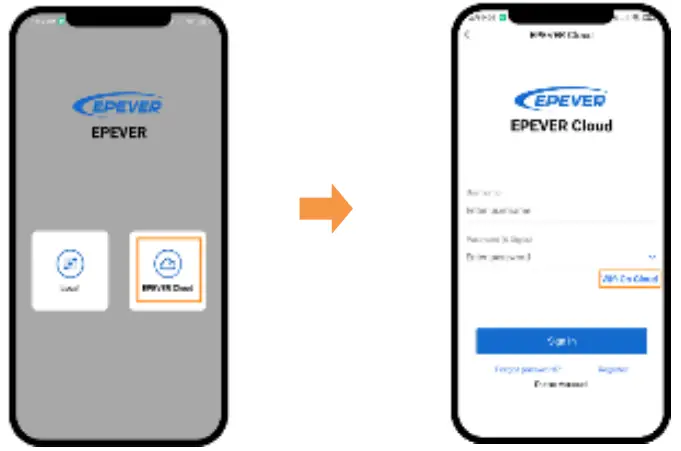 | |
| Step2: Open the APP and click the “EPEVER Cloud” icon to enter the login page. | Step3: Click the “Wifi On Cloud”icon to jump to the network connection page. |
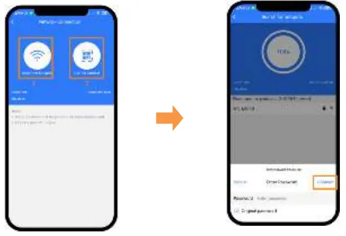 | |
| Step4: Connect the WiFi terminal to the 2.4G WiFi network by searching for the hotspots or scanning the QR code. | Step5: (Take the “Search for hotspots” as an example.) Click the hotspot’s name, input the password or tick the “Original password” checkbox. Then click the “Connect” icon. |
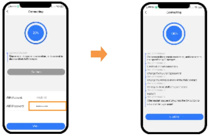 | |
| Step6: Input the WiFi password, and click the “Write” to connect the WiFi network. | Step7: After the connecting shows 100%, click the “Confirm” to return to the APP home page. |
Step8: On the APP home page, click the “EPEVER Cloud” icon to jump to the login page. Input the user name and password, click the “Sign In” to enter the main page. Users remotely monitor the field devices by a mobile phone. Note: Users can also operate the remote monitoring by the cloud platform (https://iot.epsolarpv.com/).
Operation Steps:
Scenario 2: There is no local 2.4G WiFi network. The WiFi terminal cannot upload the collected data to the EPEVER cloud.
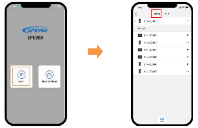 | |
| Step1: Turn on the WiFi switch on the mobile phone. Open the APP and click the “Local” to enter the “WiFi” connection page. | Step2: Click the WiFi terminal, connect it to the APP by following the prompts. Then enter the local monitoring (only the downloaded models can be monitored). |
Specifications
| Model Parameters | EPEVER WiFi 2.4G RJ45 A | EPEVER WiFi 2.4G DB9 B |
| Input voltage | DC5V | |
| Power consumption | Peak emission: 5V0100mA; Idle: 5VO40mA | |
| Enclosure | IP54 | |
| Communication method | RS485 | |
| Com. parameters | 9600 – 115200bps, 8N1 | |
| Working Frequency | 2.4-2.4835GHz | |
| Antenna gain | 2.5dBi- 5dBi | |
| Environment temp. | -40°C- 85°C | |
| Com. standard | EPEVER general communication standard V1-1.0 | |
| Com. protocol | EPEVER loT communication protocol V1.1 | |
| Com. port | RJ45 | DB9 |
| Dimension | 66.24* 51.28* 23.76mm | 101.2* 64* 26mm |
| Net weight | 37g | 38g |
Disclaimers
The warranty does not apply to the following conditions:
- Damage caused by improper use or inappropriate environment.
- The parameter setting exceeds the WiFi terminal’s limit.
- Damage caused by working temperature exceeds the rated range.
- Unauthorized dismantles or attempted repairs.
- Damage caused by force majeure.
- Damage occurred during transportation or handling.
Any changes without prior notice! Version number: V1.4
HUIZHOU EPEVER TECHNOLOGY CO., LTD.
Tel :+86-10-82894896/82894112/+86-752-3889706
Website :www.epever.com


