
EPEVER-WiFi-2.4G-RJ45-A WiFi Transmission Terminal
※ Thanks for selecting the EPEVER WiFi transmission terminal; please read this manual carefully before using the product.
※ Please keep this manual for future reference.
Wi-Fi Transmission Terminal
EPEVER-WiFi-2.4G-RJ45-A
EPEVER-WiFi-2.4G-DB9-B
Overview
The WiFi transmission terminal is specially designed for our solar controller, inverter, or inverter/charger. The WiFi transmission terminal can automatically upload data to the cloud server based on wireless transmission technology after connecting to the local wireless network. The device connected to the WiFi transmission terminal can be remotely monitored through the cloud server or mobile APP, which makes communication and data transmission easier and more convenient.
Features
- Wireless monitoring the solar controller, inverter, or inverter/charger
- Support cloud server or APP communication
- Convenient connection and operation
- Adopt high-performance M4 core CPU
- Ultra-low power consumption and high-speed data processing capabilities
- Directly powered by the communication port
- Up to 50 meters communication distance
- Supports the AP and STA working mode.
- One-key to restore factory settings
Appearance
EPEVER-WiFi-2.4G-RJ45-A
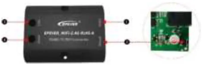
- Interface instruction
No. Name Instruction ❶ RJ45 port Connect to solar controller, inverter, or inverter/charger ❷ Reload button One key to restore factory settings
Note: Long press the Reload button with a sharp object, the Link indicator flashes twice quickly, and the factory settings are restored successfully.❸ Link indicator Display communication status ❹ Power indicator Display power status Indicator instruction
Indicator Status Instruction Link indicator ON solid in green Connect to WIFI successfully. OFF Not connect to WiFi. Fast flashing in green Reset to the factory mode. Power indicator ON solid in green Normal powered on OFF Not powered on
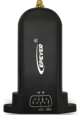
EPEVER-WiFi-2.4G-DB9-B
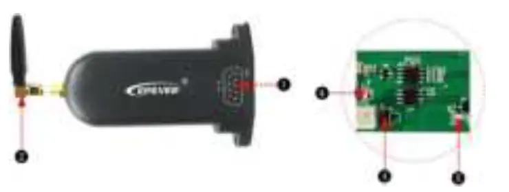
- Interface instruction
No. Name Instruction ❶
DB9 male connector« Connect to solar controller, inverter, or inverter/charger ❷ Antenna Enhance the signal transmission ❸ Reset button One key to restore factory settings
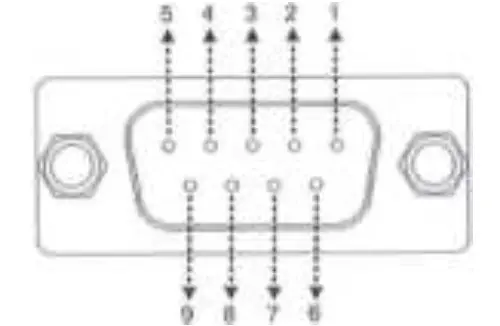
Note: The Reset button is located on the internal circuit board. Disassemble the shield first, press and hold the Reset button when the power is on, the indicator light flashes twice quickly, and the factory settings are restored successfully.❹ Network Indicator Display communication status ❺ Power Indicator Display power status EPEVER-WiFi-2.4G-DB9-B is connected to the solar controller, inverter, or inverter/charger by a DB-9 female connector. The wire sequence and name of the DB9 female connector are shown below.

No. Name Instruction No. Name Instruction 1 NC Floating 6 NC Floating 2 NC Floating 7 RS485-A RS485-A 3 VCC2 Input DC voltage 12V/200mA 8
RS485-B RS485-B 4 GND2 DC Power GND2 9 VCC1 Power1 (5V/200mA) 5 GND1 DC Power GND1 — - Indicator instruction
Indicator Status Instruction Network Indicator ON solid in green Connect to WiFi successfully. OFF Not connect to WiFi. Fast flashing in green Reset to the factory mode. Power Indicator ON solid in green Normal powered on OFF Not powered on
Working procedures
Step1: Connect the WiFi transmission terminal to the controller, inverter, or inverter/charger through the RJ45 port or the DB9 connector. For example: 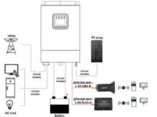
Note :EPEVER-WiFi-2.4G-RJ45-A is suitable for the controller, inverter, or inverter/charger designed with an RJ45 port. EPEVER-WiFi-2.4G-DB9-B is suitable for the device designed with a DB9 interface. For detailed connection cables, refer to the connected device’s accessories list.
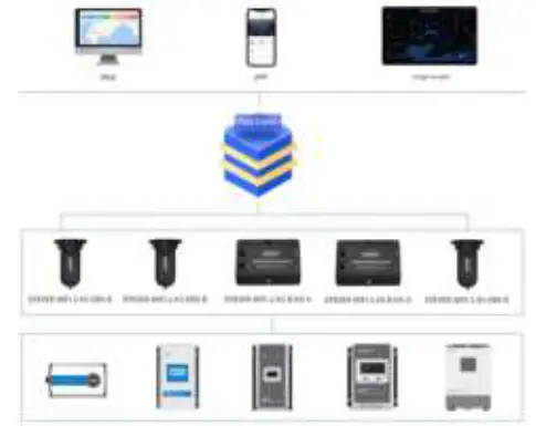
Step2: Users remotely monitor the controller, inverter, or inverter/charger through a PC, large screen, or mobile phone APP.
The phone APP supports the AP(default) and STA working mode. According to the login method and local network, it automatically enters the corresponding working mode, no need to switch the working mode manually.
- AP mode (default): When there is no local network, the WiFi terminal cannot upload data to the cloud server. All performs (including real-monitoring and parameter settings) are only carried out between mobile phone and the WiFi terminal.
Operations:
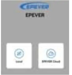
- Turn on the Wi-Fi switch on your phone and open the cloud APP.
- Click the “Local” icon to enter the “WiFi” tab.
- Click the corresponding name to connect the Wi-Fi terminal. Users can obtain the name by checking the QR code on the Wi-Fi terminal.
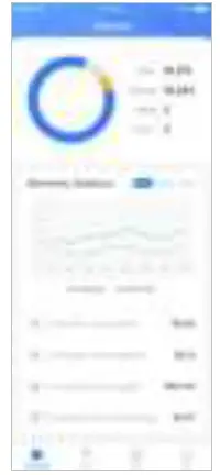
- Enter the real monitoring interface after connecting the network successfully (only downloaded product models can be monitored).

- STA mode: When there is local network, the Wi-Fi terminal uploads data to the cloud server automatically.
Operations:
- Connect the phone to local network.
- Open the cloud APP, and click the “EPEVER Cloud” icon to enter the login interface.

- Click the “Wifi On Cloud” icon to enter the “Network Connection” interface.
- Connect the network by searching the hotspots or scanning the QR code on the WiFi terminal. After successful network connection, the WiFi terminal is added into the cloud server automatically.
- Click the “Confirm” button to return the initial login interface.
- Input the user name and password. Click the “Sign In” button to enter the cloud interface. All devices added into the cloud server can be monitored by the phone APP.
Specifications
| Model Parameters | EPEVER-WiFi-2.4G-RJ45-A | EPEVER-WiFi-2.4G-DB9-B |
| Input voltage | DC5V | |
| Power consumption | Peak emission voltage: 5V@100mA Idle voltage: 5V@40mA | |
| Enclosure | IP54 | |
| Communication method | RS485 | |
| Communication parameters | 9600~115200Bps, 8N1 | |
| Working Frequency | 2.4~2.4835GHz | |
| Antenna gain | 2.5dBi~ 5dBi | |
| Working temperature | -40℃~ 85℃ | |
| Communication standard | EPEVER general communication standardV1-1.0 | |
| Communication protocol | EPEVER IoT communication protocol V1.1 | |
| Communication port | RJ45 | DB9 |
| Dimension | 66.24* 51.28* 23.76mm | 101.2* 64* 26mm |
| Net weight | 37g | 38g |
Disclaimers
The warranty does not apply to the following conditions:
- Damage caused by improper use or inappropriate environment.
- The parameter setting exceeds the WiFi terminal’s limit.
- Damage caused by working temperature exceeds the rated range.
- Unauthorized dismantling or attempted repair.
- Damage caused by force majeure.
- Damage occurred during transportation or handling.


