
EPEVER TCP RJ45 A Serial Device Server
Thanks for selecting the EPEVER TCP RJ45 A serial device server; please read this manual carefully before using the product.
Please keep this manual for future reference.
Overview
EPEVER TCP RJ45 A is a serial device server connecting with EPEVER solar controller, inverter, and inverter/charger via an RS485 or COM port. Communicating with the TCP network, it transfers collected data to the EPEVER cloud server to realize the remote monitoring, parameter setting, and data analysis.
Features:
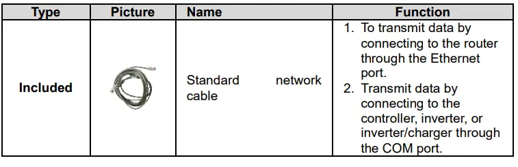
- Adopt standard network cable port
- High compatibility without any drivers
- Unlimited communication distance
- Flexible power supply for the communication interface
- Adjustable 10M/100M Ethernet port
- Designed with low power consumption, and high running speed
Appearance
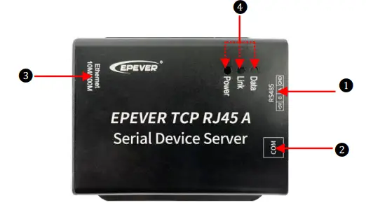
| No. | Port | Instruction |
| ① | RS485 interface(3.81-4P) | To connect the solar controller, inverter, and inverter/charger« |
| ② | COM port(RJ45) | To connect the solar controller, inverter, inverter/charger, and PC« |
| ③ | Ethernet port | To connect the router |
| ④ | Indicator | To indicate the working status |
When connecting to EPEVER solar controller, inverter, or inverter/charger, ① and ② can only choose one interface to use (except XTRA-N series). Connect the serial device server to the XTRA-N controller through the COM port and connect it to an external 5V power supply through the RS485 interface.
Indicator
| Indicator | Status | Instruction |
| Link indicator | Green ON | No communication. |
| Green flash slowly | Connect to the cloud platform successfully | |
| Power Indicator | Red ON | Normal power on |
| OFF | No power on |
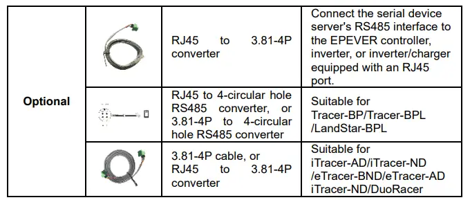
Accessories

System connection
Step1: Connect the serial device server’s RJ45 port or RS485 interface to the EPEVER controller, inverter, or inverter/charger. Take the connection diagram of the inverter/charger as an example.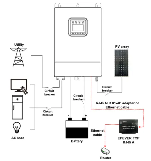
Step2: Login to the cloud platform (https://iot.epsolarpv.com) on the PC, adding the serial device server to the cloud platform. Remotely monitor the solar controllers, inverters, or inverter/charger through the cloud platforms, mobile APP, and large-screen devices. Detail operations refer to the Cloud User Manual.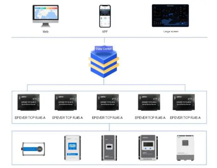
Specifications
| Model | EPEVER TCP RJ45 A |
| Input voltage | DC5V±0.3V (XTRA-N needs an extra power supply); other devices do not need additional power. |
| Standby consumption | 5V@50mA |
| Working power consumption | 0.91W |
| Communication distance | Unlimited communication distance |
| Ethernet port | 10M/100M adaptive Ethernet port |
| Serial port baud rate | 9600bps ~ 115200bps(default 115200bps, 8N1) |
| Communication port | RS485 standard |
| Bus standard | RS485 |
| Dimension | 80.5 x 73.5 x 26.4mm |
| Mounting hole size | Φ 4.2 |
| Working temperature | -20 ~ 70℃ |
| Enclosure | IP30 |
| Net Weight | 107.7g |


