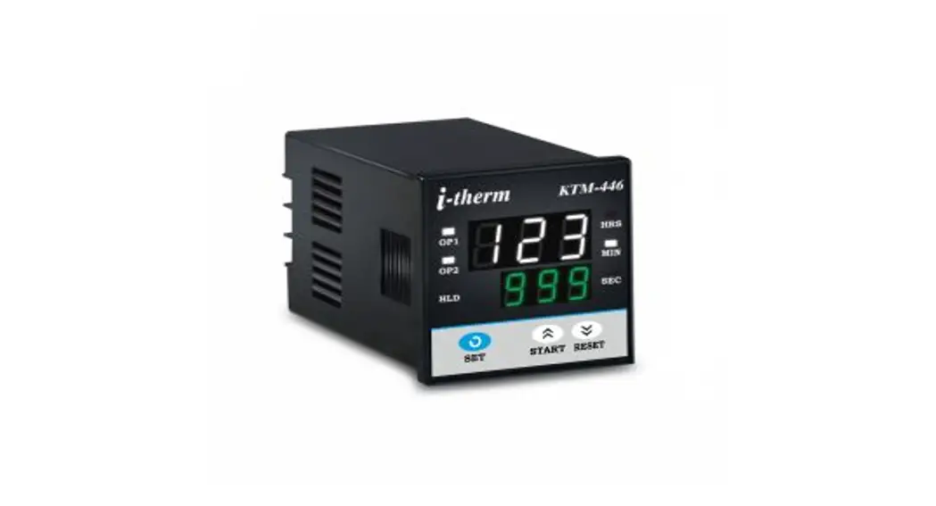
![]() USER’S OPERATING MANUAL FOR DIGITAL PRESET TIMER
USER’S OPERATING MANUAL FOR DIGITAL PRESET TIMER
(Models: KTM-446 / 776 / 996 / 666 )
SPECIFICATIONS :
Display
: Double 3 Digit 7-segment LED,
3 Digit Bright White (Running Time)
3 Digit Luminous Green ( S e t Time)
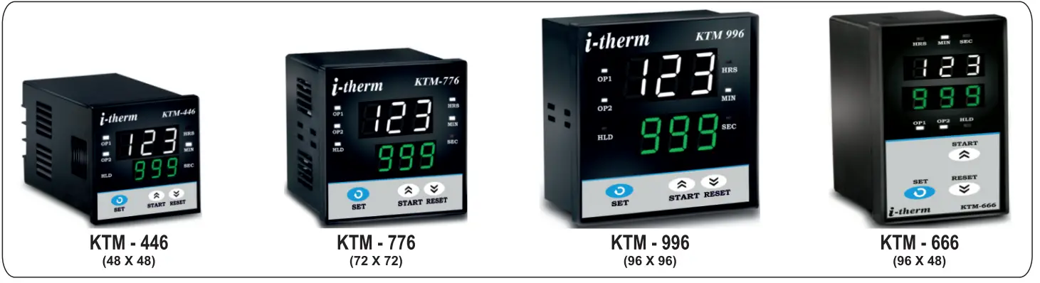
| Model no. | KTM – 446 | KTM – 776 | KTM – 996 | KTM – 666 |
| Display height (PV) | 0.39″ | 0.56″ | 0.80″ | 0.39″ |
| Display height (SV) | 0.24″ | 0.39″ | 0.56″ | 0.39″ |
| Status Indication | : Time unit (Hrs. / Min. /Sec. ) Relay status (RL1/RL2) Auto Reset / Hold Time |
| Time settings | : Through Keyboard |
| Control Inputs | a] StartInput b ] Reset |
| Reset time | :<100 ms |
| Timing Accuracy | :0.05% Full Scale |
| Repeat Accuracy | :0.01% |
| Outputs | :5Amp @ 230VAC Relay (1C/O) x 2 12 VDC@30mA for SSR Drive ( by order ) |
| Reset | : a] Front switch (Programmable) b ] Remote Reset (via rear terminals) c] On power interruption (Programmable) |
| Supply | : 90 to 2 7 0 VAC |
| Mounting | : Panel |
| Housing | : ABS Plastic |
| Operatingtemp. | :0~50°C |
| Humidity | : 95% Rh (Non Condensing). |
Configurable Parameters
| Mode | : On delay/Off delay/CY1/CY2/CY3 |
| Range 1&2 | : 9.99 Sec. to 999 Hrs. ( Programmable ) |
| Count direction | : Up/Down |
| Timer Start | : Refer Programming |
| Timer Function | : Auto Reset / Latched output |
| Front Reset | : Enable / Disable |
| Gate Input | : Enable / Disable |
| Memory Backup | : Enable / Disable |
| Output 2 Function | : Refer Programming |
OVER ALL DIMENSIONS & PANEL CUT OUT (IN MM)
MODEL:- KTM-446/ KTM-776/ KTM-996/ KTM-666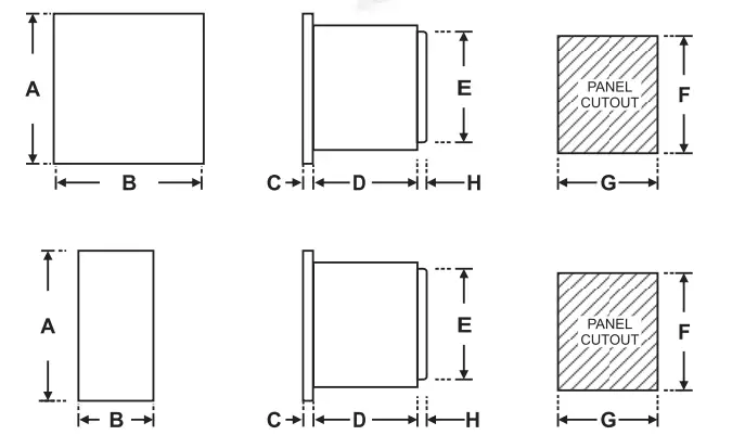
| Dim / Mode | A | B | C | D | E | F | G | H |
| KTM-446 | 48 | 48 | 8 | 75 | 43 | 44 | 44 | 9 |
| KTM-776 | 72 | 72 | 10 | 65 | 66 | 68 | 68 | 9 |
| KTM-996 | 96 | 96 | 10 | 45 | 89 | 92 | 92 | 9 |
| KTM-666 | 96 | 48 | 10 | 45 | 89 | 92 | 44 | 9 |
INSTALLATION GUIDELINES
- Prepare the cut-out with proper dimension as shown in figure.
- Remove clamp from controller
- Push the controller through panel cut-out and secure the controller in its place by tightening the side clamp.
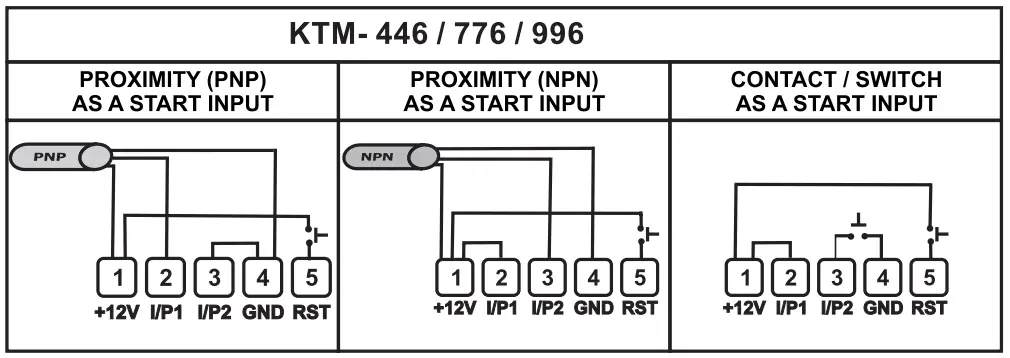
TERMINAL CONNECTIONS :
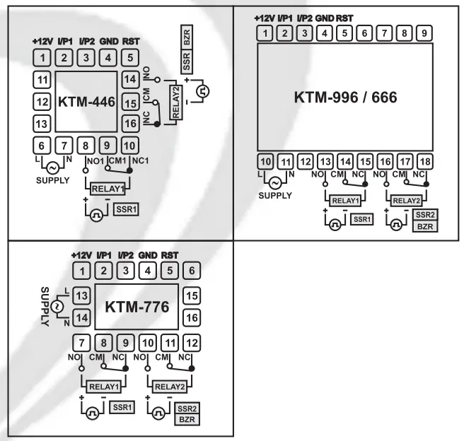
TYPICAL APPLICATION :
SAFETY INSTRUCTION
All safety related instruction appearing in this manual must be followed to ensure safety of the operator as well as the unit..
MECHANICAL
- Ambient temperature and relative humidity surrounding the Timer must not exceed the maximum specified limits..
- The Timer in its installed state must be protected against excessive electrostatic or electromagnetic interferences.
ELECTRICAL
- The Timer must be wired as per wiring diagram & it must . comply with local electrical regulation.
- The Electrical noise generated by switching inductive loads might create momentary Fluctuation in display, latch up, data loss or permanent damage to the instrument. To reduce this use snubber circuit across the load.
PROGRAMMING
USER LIST : To access the user list press & release SET key once.
| PARAMETER | DISPLAY | RANGE | DESCRIPTION | DEFAULT | |
| HOLD TIME |  | -0,100. S | HOLD TIME : Prompted only if selected mode is CY3 (Cyclic with Hold). | 5.0 | |
| Sets the HOLD time between motor Forward & Reverse. | |||||
| SET TIME 1 |  |  | 0 – 999 | SET TIME 1 : Set time for On delay & Off delay modes. On time for CY1 | 10.0 |
| & CY2 modes. Forward time for CY3 mode. | |||||
| SET TIME 2 |  | | 0 – 999 | SET TIME 2 : Prompted only if selected timer mode is CY1, CY2 or CY3. | 10.0 |
| It sets Off time for CY1 & CY2 modes& reverse time for CY3 mode. | |||||
| NUMBER OF CYCLES |  |  | 0 – 999 | NUMBER OF CYCLES : Prompted only if selected timer mode is CY1, | 0 |
| CY2. It sets the number of cycles after which both the Relays will be OFF. | |||||
| EOC TIME |  |  | 0 – 999 | EOC TIME : OP2 function is set to EOC. This parameter sets the End of | 5.0 |
| cycle time ( Fixed in seconds) | |||||
| TOTAL TIME |  | | 0 – 999 | TOTAL TIME . Available for CY3 mode only. In This mode when Total | 0 |
| s over (Programmed in Min. only); Both relays will be off. time is | |||||
CONFIGURATION LIST :
- To Enter in this mode press SET key for 6 sec. at Power On. “..-” Message will be displayed for 6 sec. Now unit will allow the user to configure different parameters with options as described below.
- Press “SET” Key to move on to next parameter.
- Press UP or DOWN Key to scroll between parameter options.
- All following parameters as shown in the shaded will be displayed on Lower Display
| PARAMETER | LOWER DISPLAY | UPPER DISPLAY | DESCRIPTION | DEFAULT |
| TIMER FUNCTION |  | 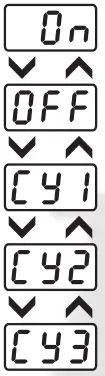 | ON DELAY : Outputs are de-energized at power on. It remains De-energized after | ON DELAY |
| start of timing cycle. After completions of timing cycle outputs are energized. | ||||
| OFF DELAY: Outputs are energized at the start of timing cycle. After completions | ||||
| of timing cycle outputs are de-energized. | ||||
| CYCLIC WITH OFF TIME FIRST : Sti : Off-time | ||||
| St2 : On-time | ||||
| CYCLIC WITH ON TIME FIRST : Sri : On-time | ||||
| St2 : Off-time | ||||
| CYCLIC WITH HOLD TIME : StH : Hold Time | ||||
| St1 : Forward-Time ; St2 : Reverse-Time | ||||
| RANGE 1 |  | 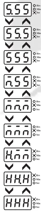 | TIMER RANGE & RESOLUTION : Range : 9.99 Sec. | 999 SEC. |
| Resolution : 0.01 Sec. | ||||
| Range : 99.9 Sec. Resolution : 0.1 Sec. | ||||
| Range : 999 Sec. Resolution : 1 Sec. | ||||
| Range : 9 Min. 59 Sec. Resolution : 1 Sec. | ||||
| Range :99.9 Min. Resolution : 0.1 Min. | ||||
| Range :999 Min Resolution : 1 Min. | ||||
| Range : 9 Hrs. 59 Min. Resolution :1 Min. | ||||
| Range : 99.9 Hrs. Resolution : 0.1 Hrs. | ||||
| Range : 999 Hrs. resolution : 1 Hrs. | ||||
| RANGE 2 |  | 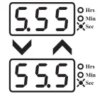 | TIMER RANGE & RESOLUTION: Range : 9.99 Sec. | |
| Resolution : 0.01 Sec. | ||||
| Range : 99.9 Sec. Resolution : 0.1 Sec. |
| RANGE 2 | 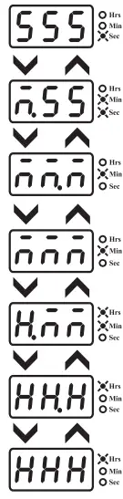 | Range :999 Sec. Resolution : 1 Sec. | 999 SEC. | |
| Range : 9 Min. 59 Sec. Resolution : 1 Sec. | ||||
| Range : 99.9 Min. Resolution : 0.1 Min. | ||||
| Range : 999 Min. Resolution : 1 Min. | ||||
| Range : 9 Hrs. 59 Min. Resolution : 1 Min. | ||||
| Range : 99.9 Hrs. Resolution : 0.1 Hrs. | ||||
| Range : 999 Hrs. resolution : 1 Hrs. | ||||
| HOLD TIME |  | 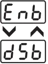 | Hold Time :- This parameter will be prompted ONLY when timer function selected as C Enable : If selected, user can view & edit Hold time in user list. Disable : If selected, user can only view th Hold Time but cannot edit it in user list. | ENABLE |
| TIMER DIRECTION |  |  | TIMER COUNTING DIRECTION : UP COUNTING : If Selected, timer starts counting from 0 to set time in ascending | DOWN COUNT |
| order. ( Up direction ) DOWN COUNTING : If Selected, timer starts counting from Set time to 0 in descending order. ( Down direction ) | ||||
| TIMER START |  |  | TIMER START MODE : This parameter defines the Start mode for the timer. | POWER ON START |
| POWER ON START : If Selected , Timer starts counting at Power On. | ||||
| FRONT START : Timer starts only after user presses START key. If the cycle is | ||||
| incomplete at the time of power fail , It will continue after power is restored without need for re-issuing the Start command from front key ( If MEM=On ). Not valid for CY3 mode FRONT START : Timer starts only after user presses START key. If the cycle is not over at the time of power fail, It will not start till the START command is issued from the front panel (If MEM=On). Not valid for CY3 mode. REMOTE START ( EDGE TRIGGERING ) Timer starts counting only when it detects high to low pulse at back terminal from external Input. REMOTE START WITH LEVEL SENSING Timer starts counting only when it detects high to low pulse at back terminal from external Input. The input signal must remain low during timing cycle otherwise timer will Reset. | ||||
| TIMER MODE |  | 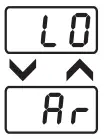 | TIMER MODE : Prompted only if selected function is ON/OFF Delay & start input is | LATCH OUTPUT |
| other than power on start. For power on start this function is always set to LO BeideHED MODE : In this mode once the timing cycle is over, User must issue a Reset signal from front key( if F.rt= On) or Ext. Reset input to re-start the timer. AUTO RESET MODE : In this mode once the timing cycle is over, Next start input either thro’ Front panel or thro’ external input signal will re-start the timer. | ||||
| GATE INPUT |  |  | GATE INPUT : Prompted only if Timer is configured for either power on start or | NO |
| front start. When enabled ( Set to yes ) the external input can work as a Gate input. DISABLE (nO) : The external input can not be used as a Gate input. | ||||
| ENABLE (YES) : The external input can be used as a Gate input. | ||||
| FRONT RESET |  |  | FRONT RESET ENABLE/DISABLE : This parameter allows the user to Enable or | YES |
| Disable front Reset function. This feature prevents un-authorized attempt to Reset the Timer during Run mode. DISABLE (nO) : The Timer can not be reset through front panel. ENABLE (YES) : The Timer can be reset through front panel. | ||||
| MEMORY BACKUP |  |  | MEMORY BACKUP ENABLE/DISABLE : This parameter allows the user to | NO |
| Enabe or Disable memory backup function. DISABLE (nO) : No memory backup for run time value. ENABLE (YES) : Memory backup for run time value. | ||||
| OUTPUT 2 FUNCTION |  |  | OUTPUT 2 FUNCTION : This parameter will be prompted only if selected Timer | AUC |
| function is either ON or OFF delay. Not applicable for Cyclic modes. END OF CYCLE OUTPUT : The OP2 is energized for rt period set in user list at the | ||||
| end of timing cycle. AUXILLIARY CONTACT : The OP2 will operate simultaneously with OP1. This | ||||
| function is required when user needs 2 changeover Relay contacts. INSTANT CONTACT : The OP2 function as a instant contact which operates | ||||
| immediately when timer starts & remains in that state till the start of next cycle. OFF : The OP2 is not used & can be kept reserve for future use. |
Function / Timing Waveforms
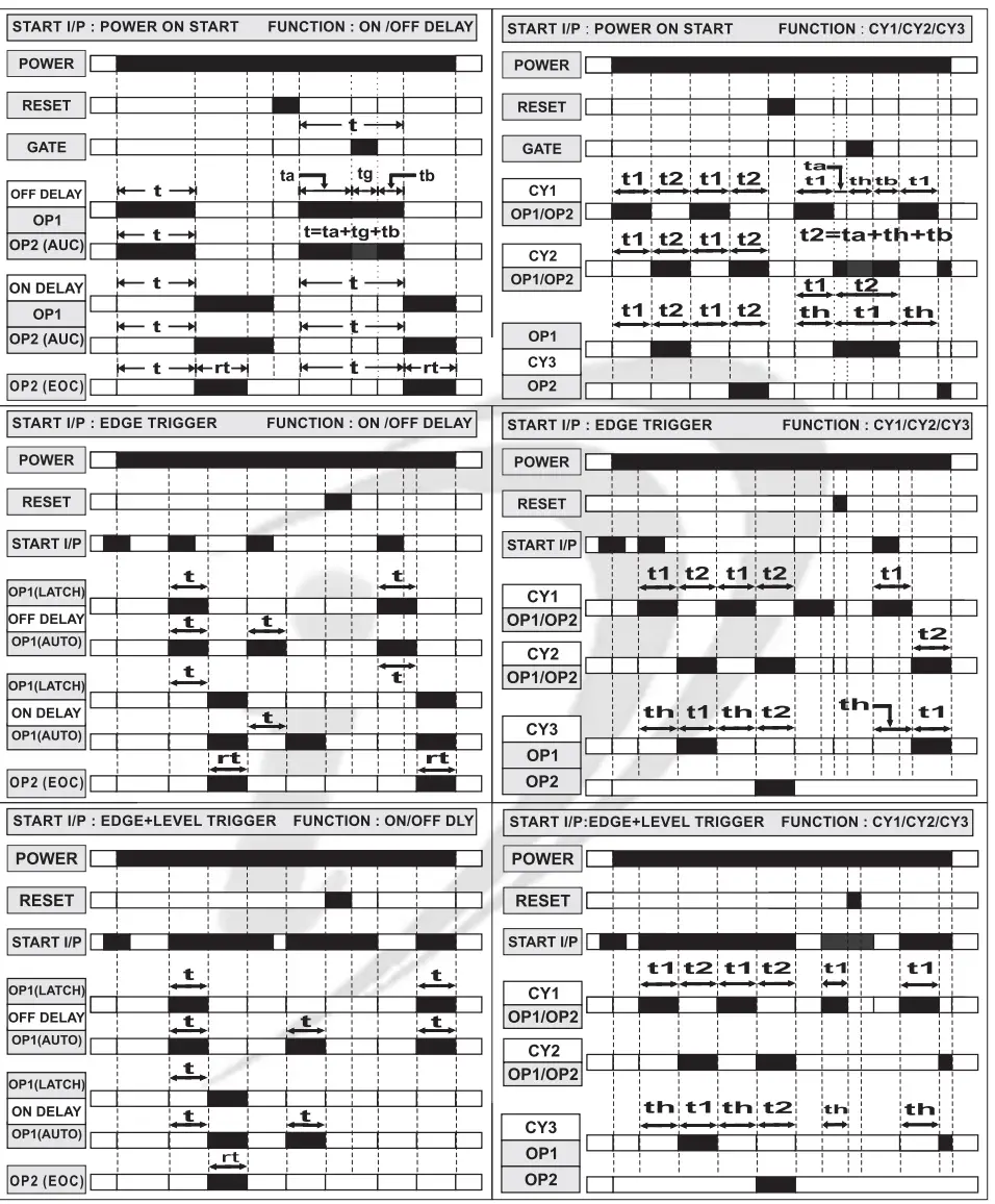
ABBREVIATION
EOC : END OF CYCLE
LATCH : LATCHED 0/P MODE
AUTO : AUTO RESET MODE
t : SET TIME
rt : END OF CYCLE TIME
tg : GATE PULSE PERIOD
CY 1
t1 : ON TIME
t2 : OFF TIME
CY2
t1 : OFF TIME
t2 : ON TIME
CY3
th : HOLD TIME
t1 : FORWARD TIME
t2 : REVERSE TIME
![]() Mfgd by: Innovative Instruments & Controls LLP
Mfgd by: Innovative Instruments & Controls LLP
206, New Sonal Link Service Industrial Premises Co-op Society Ltd,
Building No.2, Link Road, Malad (W), Mumbai – 400064.
Tel: 022-66939916/17/18;
E-mail : [email protected]
Website : www.itherm.co.in https://www.youtube.com/channel/UCzWGtv0HuHUgZR4KKRyKG1w/videos
OIM KTM – XX6 V1.1


