Altronix SMP5PM Supervised Power Supply Charger
SMP5PM
Supervised Power Supply/Charger
Installation Guide
Overview:
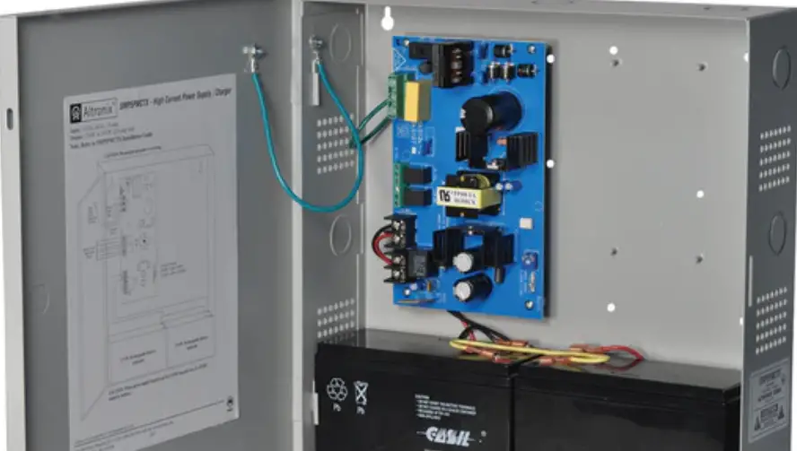
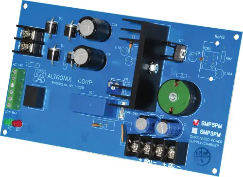
Altronix SMP5PM is a supervised power supply/charger that converts a low voltage AC input into a 12VDC or 24VDC selectable output with 4A of continuous supply current (see specifications). This general purpose power supply has a wide range of applications for access control, security and CCTV system accessories that require additional power.
Specifications:
Input:
- 24VAC or 28VAC (See Voltage Output/Transformer Selection Table).
Output:
- 12VDC or 24VDC selectable output.
- 4A supply current.*
- Filtered and electronically regulated outputs.
- Short circuit and thermal overload protection.
Supervision:
- AC fail supervision (form “C” contacts).
- Low battery supervision (form “C” contacts).
Battery Backup:
- Built-in charger for sealed lead acid or gel type batteries.
- Maximum charge current 0.3A.
- Zero voltage drop when switching over to battery backup.
Visual Indicators:
- AC input and DC output LED indicators.
Board Dimensions (W x L x H approx.):
7” x 4.05” x 1.35” (177.8mm x 102.9mm x 34.3mm)
Specified at 25˚C ambient
Voltage Output/Transformer Selection Table:
| Output VDC | Switch Position | Max. Load DC | Transformer Requirements |
| 12VDC | SW1 ON | 4A | 24VAC or 28VAC / 100VA (T2428100) |
| 24VDC | SW1 OFF | 4A | 24VAC or 28VAC / 175VA (T2428175) |
Note: Transformers with higher VA ratings may be used for all output voltages above as long as you do not exceed 28VAC or 45VDC.
Installation Instructions:
SMP5PM should be installed in accordance with the National Electrical Code and all applicable Local Regulations.
- Mount SMP5PM board in the desired location/enclosure (mounting hardware included).
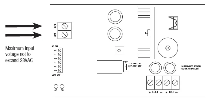
- Set SMP5PM to the desired DC output voltage via SW1 (Voltage Output/Transformer Selection Table).
- Connect proper transformer to the terminals marked [AC] (Voltage Output/Transformer Selection Table). Use 18 AWG or larger for all power connections (Battery, DC output).
Use 22 AWG to 18 AWG for power-limited circuits (AC Fail/Low Battery reporting).
Keep power-limited wiring separate from non power-limited wiring (115VAC / 60Hz Input, Battery Wires). Minimum 0.25” spacing must be provided.
CAUTION: Do not touch exposed metal parts.
Shut branch circuit power before installing or servicing equipment.
There are no user serviceable parts on board.
Refer installation and servicing to qualified service personnel. - Measure output voltage before connecting devices. This helps avoiding potential damage.
- Connect devices to be powered to the terminals marked [+ DC –].
- When the use of standby batteries is desired, they must be lead acid or gel type.
Connect battery to the terminals marked [+ BAT –] on the board (battery leads included).
Use two (2) 12VDC batteries connected in series for 24VDC operation.
Note: When batteries are not used, a loss of AC will result in the loss of output voltage. - Connect appropriate signaling notification devices to AC Fail & Low battery supervisory relay outputs marked [NC, C, NO].
LED Diagnostics:
| Red (DC) | Green (AC) | Power Supply Status |
| ON | ON | Normal operating condition |
| ON | OFF | Loss of AC. Standby battery is supplying power. |
| OFF | ON | No DC output. |
| Off | Off | Loss of AC. Discharged or no standby battery. No DC output. |
Terminal Identification:
| Terminal Legend | Function/Description |
| AC/AC | Low voltage AC input (Voltage Output/Transformer Selection Table). For 12VDC output use 16VAC or higher with 85VA power rating or higher. For 24VDC output use 28VAC with 140VA power rating or higher.Caution: Do not apply voltages above 28VAC (28VAC is maximum input rating). |
| + DC – | 12VDC/24VDC @ 4A continuous output. |
| AC FAIL NC, C, NO | Used to notify loss of AC power, e.g. connect to audible device or alarm panel. NC, C, NO Relay normally energized when AC power is present. Contact rating 1A @ 120VAC / 28VDC. |
| Low Battery NC, C, NO | Used to indicate low battery condition, e.g. connect to alarm panel. NC, NO, C Relay normally energized when DC power is present. Contact rating 1A @ 120VAC / 28VDC. Low battery threshold: |
| + BAT – | Standby battery connections. Maximum charge rate 0.3A. |
Altronix is not responsible for any typographical errors.
140 58th Street, Brooklyn, New York 11220
USA
phone: 718-567-8181
fax: 718-567-9056
website: www.altronix.com
e-mail: [email protected]
Lifetime Warranty
IISMP5PM – Rev. 090710 F18U


