Altronix SMP5CTX Supervised Power Supply Charger
Overview:
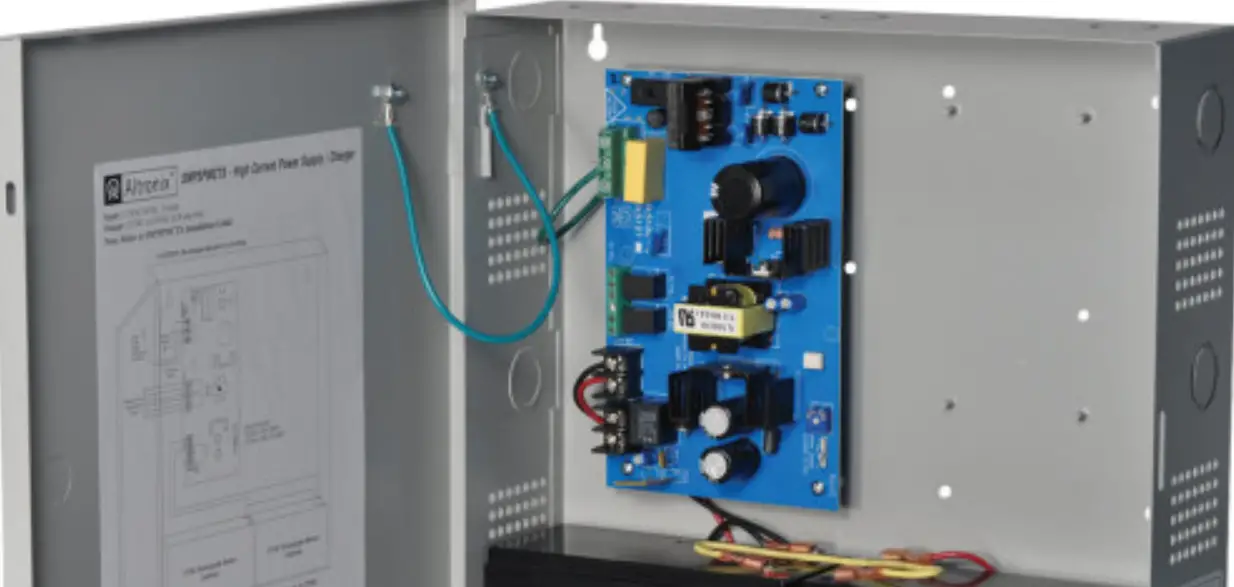
Altronix SMP5CTX Series power supply/chargers convert a 115VAC or 230VAC, 50/60Hz input into a regulated 12VDC or 24VDC output up to 4A of continuous load current (see specifications).
SMP5CTX Series Power Supply Configuration Reference Chart:
| Altronix Model Number | Accessory Power Distribution Module(s) | Number of Outputs | Fused Outputs | PTC Outputs (auto-resettable) | Individual Output Rating (A) | Supervised | 115VAC/ 230VAC Input Current (A) | 12/24VDC Total Output Current (A) |
| SMP5CTX | – |
0.95A/ 0.5A | ||||||
| SMP5PMCTX | – | 1 | – | – | 4A | |||
| SMP5PMCTXX | ||||||||
| SMP5PMP4 | PD4 | 4 | ✓ | – | 3.5A | |||
| SMP5PMP4CB | PD4CB | – | ✓ | 2.5A | ✓ | 4A | ||
| SMP5PMP8 | PD8 | 8 | ✓ | – | 3.5A | |||
| SMP5PMP8CB | PD8CB | – | ✓ | 2.5A | ||||
| SMP5PMP16 | PD16W | 16 | ✓ | – | 3.5A | |||
| SMP5PMP16CB | PD16WCB | – | ✓ | 2.5A |
Agency Listings:
- CE European Conformity.
Input:
- Input 115VAC, 50/60Hz, 0.95A or 230VAC, 50/60Hz, 0.5A.
Output:
- 12VDC or 24VDC selectable output.
- 4A supply current.
- Filtered and electronically regulated outputs.
- Short circuit and thermal overload protection.
Battery Backup:
- Built-in charger for sealed lead acid or gel type batteries.
- Maximum charge current 0.5A.
- Zero voltage drop when switching over to battery backup.
Visual Indicators:
- AC input and DC output LED indicators.
Features:
- Power ON/OFF switch.
Specifications:
Supervision (select models):
- AC fail supervision (form “C” contacts).
- Low battery supervision (form “C” contacts).
Electrical:
- Operating temperature: 0ºC to 49ºC ambient.
Mechanical:
- Enclosure Dimensions (H x W x D approx.): SMP5CTX, SMP5PMCTX, SMP5PMP4, SMP5PMP4CB, SMP5PMP8, SMP5PMP8CB, SMP5PMP16, SMP5PMP16CB:
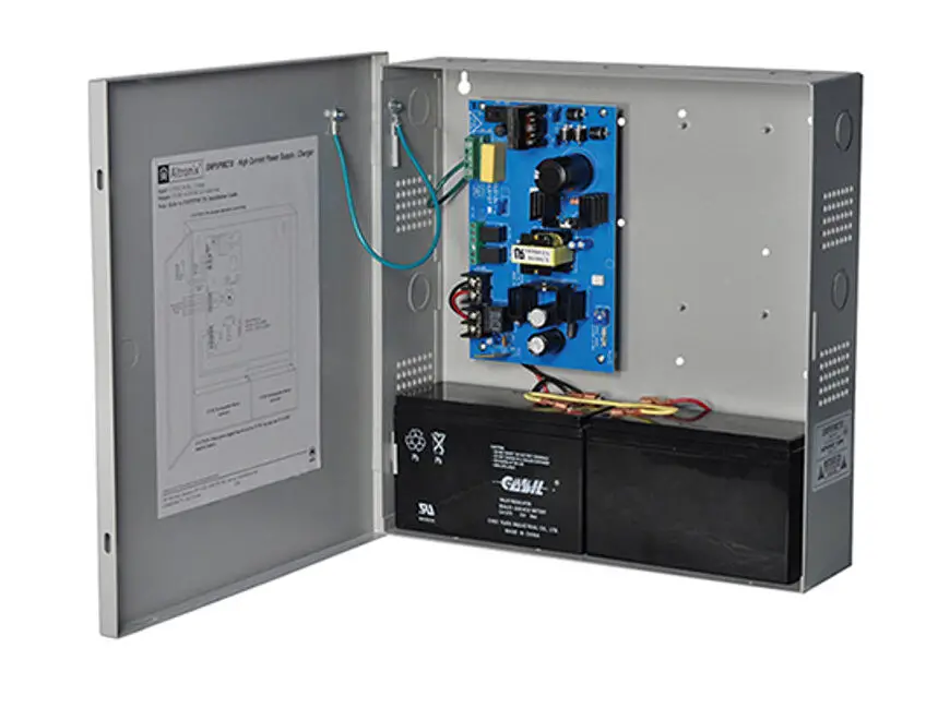
13.5” x 13” x 3.25” (342.9mm x 330.2mm x 82.6mm)- Accommodates up to two (2) 12VDC/7AH batteries.
SMP5PMCTXX:
15.5” x 12” x 4.5” (393.7mm x 304.8mm x 114.3mm) - Accommodates up to two (2) 12VDC/12AH batteries.
- Accommodates up to two (2) 12VDC/7AH batteries.
Power Supply Voltage Output Specifications:
| Output VDC | Switch Position | Max. Load DC |
| 12VDC | SW1 – ON (Fig. 1c, pg. 5) | 4A |
| 24VDC | SW1 – OFF (Fig. 1c, pg. 5) | 4A |
Specified at 25˚C ambient.
Installation Instructions:
Wiring methods shall be in accordance with the National Electrical Code/NFPA 70/NFPA 72/ANSI, and with all local codes and authorities having jurisdiction. Product is intended for indoor use only.
- Mount unit in the desired location. Mark and predrill holes in the wall to line up with the top two keyholes in the enclosure. Install two upper fasteners and screws in the wall with the screw heads protruding. Place the enclosure’s upper keyholes over the two upper screws; level and secure. Mark the position of the lower two holes. Remove the enclosure. Drill the lower holes and install the three fasteners. Place the enclosure’s upper keyholes over the two upper screws. Install the two lower screws and make sure to tighten all screws (Enclosure Dimensions, pgs. 7, 8). Secure enclosure to earth ground.
- Slide [Power ON/OFF] switch t o OFF position.
- Set SW1 on the power supply board to the desired DC output voltage (Fig. 1c, pg. 5)
(Power Supply Voltage Output Specification Chart). - Connect AC power to the terminals marked [L & N], connect ground to the green flying lead (Fig. 1, pg. 5). Use 18 AWG or larger for all power connections (Battery, DC output).
Use 22 AWG to 18 AWG for power-limited circuits (AC Fail/Low Battery reporting). - Slide [Power ON/OFF] switch to ON position.
- Measure output voltage before connecting devices. This helps avoiding potential damage.
Keep power-limited wiring separate from non power-limited wiring (115/230VAC, 50/60Hz Input, Battery Wires). Minimum 0.25” spacing must be provided.
CAUTION: Do not touch exposed metal parts.
Shut branch circuit power before installing or servicing equipment.
There are no user serviceable parts inside.
Refer installation and servicing to qualified service personnel. - Slide [Power ON/OFF] switch t o OFF position.
- Connect devices to be powered:
- For Power Supply Board connect to the terminals marked [– DC +].
- For Power Distribution Module(s) connect devices to be powered to the terminal pairs 1 to 4 marked [1P & 1N] through [4P & 4N] (Fig. 2, pg. 6), 1 to 8 marked [1P & 1N] through [8P & 8N] (Fig. 3, pg. 6), or 1 to 16 marked [1P & 1N] through [16P & 16N] (Fig. 4, pg. 6), carefully observing correct polarity.
Note: Power switch is used to disconnect the L (HOT) terminal from the rest of the board (Fig. 1a, pg. 5). When servicing the unit, AC mains should be removed.
- When using stand-by batteries, they must be lead acid or gel type.
Connect battery to the terminals marked [– BAT +] (battery leads included).
12VDC operation: Use one (1) 12VDC battery.
24VDC operation: Use two (2) 12VDC batteries connected in series.
Note: When batteries are not used, a loss of AC will result in the loss of output voltage.
For supervised models only: - Connect appropriate signaling notification devices to AC Fail and Low Bat supervisory relay outputs marked [NC, C, NO] (Fig. 1b, pg. 5).
- Slide [Power ON/OFF] switch to ON position.
LED Diagnostics:
Power Supply Board
| Red (DC) | Green (AC) | Power Supply Status |
| ON | ON | Normal operating condition. |
| ON | OFF | Loss of AC. Stand-by battery is supplying power. |
| OFF | ON | No DC output. |
| OFF | OFF | Loss of AC. Discharged or no stand-by battery. No DC output. |
Power Distribution Module
| Green | Power Distribution Module Status |
| ON | Normal operating condition. |
| OFF | No Power Output. |
Terminal Identification:
Power Supply Board:
| Terminal Legend | Function/Description |
| L, G, N | Connect 115VAC/230VAC to these terminals: L to Hot, N to Neutral. |
| – DC + | 12VDC / 24VDC @ 4A continuous output. |
| AC FAIL NC, C, NO | Used to notify loss of AC power, e.g. connect to audible device or alarm panel. Relay normally energized when AC power is present. Contact rating 1A @ 120VAC / 28VDC. |
| Low Battery NC, C, NO | Used to indicate low battery condition, e.g. connect to alarm panel. Relay normally energized when DC power is present. Contact rating 1A @ 120VAC / 28VDC. Low battery threshold: 12VDC output threshold set @ approximately 10.5VDC, 24VDC output threshold set @ approximately 21VDC. |
| – BAT + | Stand-by battery connections. Maximum charge rate 0.5A. |
Note: Supervised models only
PD4/PD4CB/PD8/PD8CB/PD16W/PD16WCB – Power Distribution Module:
| Terminal Legend | Function/Description | ||
| PD4/PD4CB | PD8/PD8CB | PD16W/PD16WCB | |
| 1P to 4P | 1P to 8P | 1P to16P | Positive DC power outputs. |
| 1N to 4N | 1N to 8N | 1N to 16N | Negative DC power outputs. |
Caution: Equipment to be installed / serviced by authorized / trained personnel only.
Shut branch circuit power before installing / servicing equipment.
WARNING: To reduce the risk of fire or electric shock, do not expose the unit to rain or moisture. This installation should be made by qualified service personnel and should conform to the National Electrical Code and all local codes.
The lightning flash with arrowhead symbol within an equilateral triangle is intended to alert the user to the presence of an insulated DANGEROUS VOLTAGE within the product’s enclosure that may be of sufficient magnitude to constitute an electric shock.
The exclamation point within an equilateral triangle is intended to alert the user to the presence of important operating and maintenance (servicing) instructions in the literature accompanying the appliance.
CAUTION: To reduce the risk of electric shock do not open enclosure. There are no user serviceable parts inside. Refer servicing to qualified service personnel.
Fig. 1a
Switch disables power mains line voltage input.
If stand-by battery (batteries) are connected, the DC output remains on.
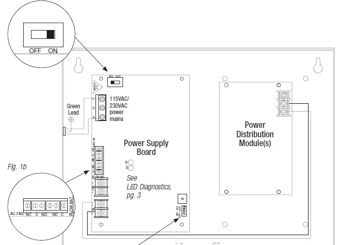

Fig. 1c
SW1
12VDC – ON
24VDC – OFF
Power Distribution Module(s):
Fig. 2 – PD4/PD4CB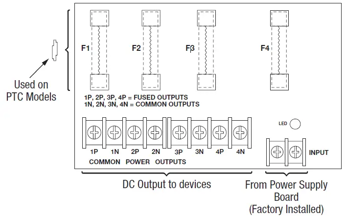 Fig. 3 – PD8/PD8CB
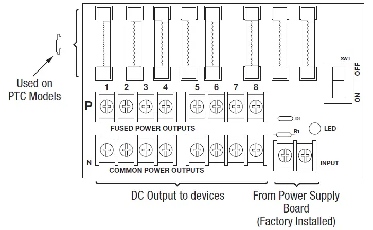 Fig. 4 – PD16W/PD16WCB
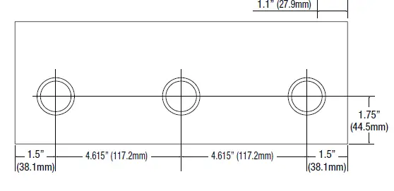
 Enclosure Dimensions (BC300): SMP5CTX, SMP5PMCTX, SMP5PMP4, SMP5PMP4CB, SMP5PMP8, SMP5PMP8CB, SMP5PMP16, SMP5PMP16CB
13.5” x 13” x 3.25” (342.9mm x 330.2mm x 82.6mm)
Enclosure accommodates up to two (2) 12VDC/7AH batteries.
Also available to accommodate up to two (2) 12VDC/12AH batteries (please contact Altronix).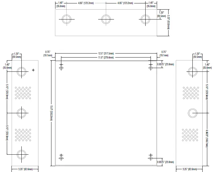
Enclosure Dimensions (BC400): SMP5PMCTXX
15.5” x 12” x 4.5” (393.7mm x 304.8mm x 114.3mm) Enclosure accommodates up to two (2) 12VDC/12AH batteries.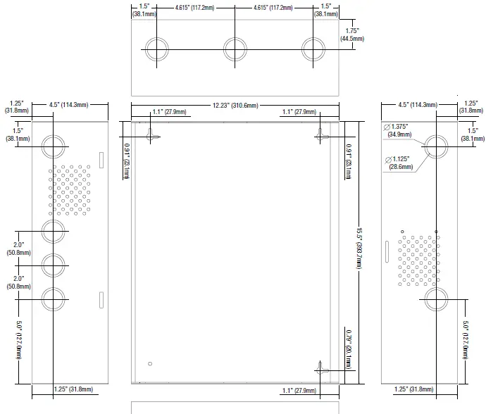
 Altronix is not responsible for any typographical errors.
140 58th Street, Brooklyn, New York 11220 USA
phone: 718-567-8181
fax: 718-567-9056
website: www.altronix.com
e-mail: [email protected]
Lifetime Warranty
IISMP5CTX Series F18U


