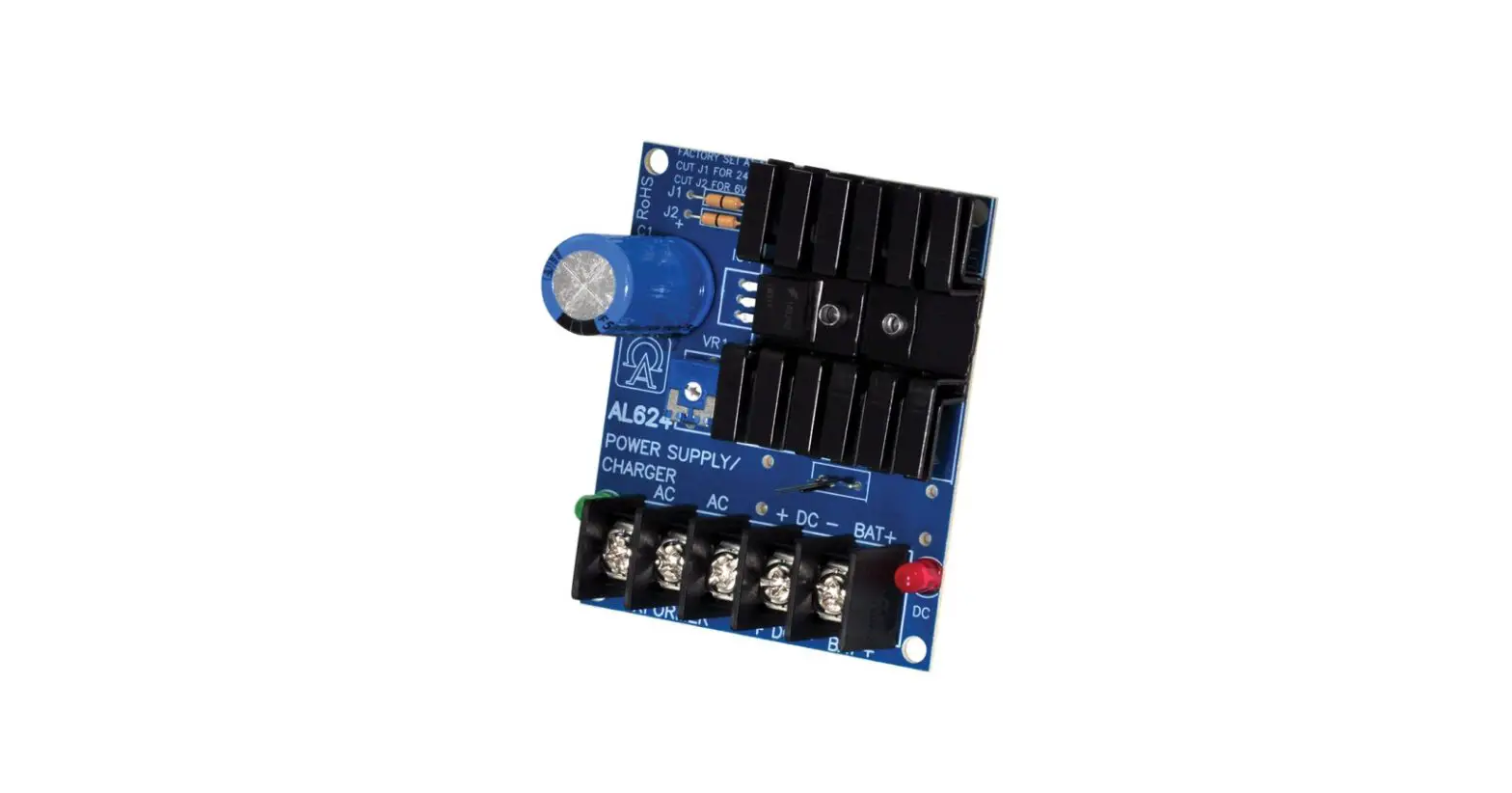
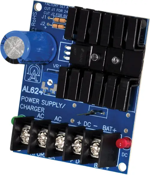
Altronix DPS1 Power Supply-Charger
Overview
DPS1 power supply/charger converts low voltage AC input into 6VDC or 12VDC @ 1.2A or 24VDC @ 750mA of continuous supply current (see specifications). This general-purpose power supply has a wide range of applications for access control, security, and CCTV system accessories that require additional power.
Specifications
Input:
- 6VDC or 12VDC output – use TP1640; 24VDC output – use T2428100.
Output:
- 6VDC, 12VDC or 24VDC selectable output.
- 1.2A continuous supply current at 6VDC-12VDC. 750mA continuous supply current at 24VDC.
- Filtered and electronically regulated output.
- Short circuit and thermal overload protection.
Visual Indicators:
- AC input and DC output LED indicators.
Battery Backup:
- Built-in charger for sealed lead acid or gel-type batteries.
- Automatic switch over to stand-by battery when AC fails.
- Maximum charge current 0.3A.
- Battery short circuit protection (circuit breaker).
Features:
- Extremely compact design.
- Includes Snap Track ST3 and clips.
- Includes battery leads.
Board Dimensions (L x W x H approx.):
- 3” x 2.5” x 1.5” (76.2mm x 63.5mm x 38.1mm).
Voltage Output/Transformer Selection Table:
| Output | Voltage Selector (JMPR) | Transformer |
| 12VDC @ 1.2A continuous supply current | Leave J1 and J2 Intact | 16.5VAC / 20 VA (Altronix model TP1620) |
| 24VDC @ 750mA continuous supply current | Cut Jumper J1 Only | 24VAC / 40 VA (Altronix model TP2440) |
| 6VDC @ 1.2A continuous supply current | Cut Jumper J2 Only | 12VAC / 20 VA (Altronix model TP1220) |
Installation Instructions
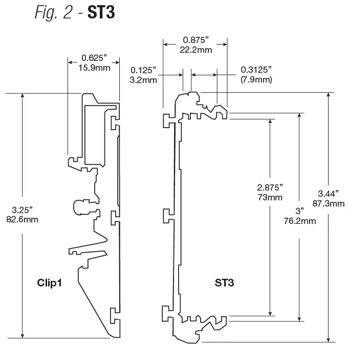
- Mount the DPS1 using included ST3 snap track and clips:
- Slide the board into the outermost slots on the ST3 (Fig. 2, pg. 2);
- Attach the clips to the back of ST3 using provided guides and slots;
- Mount the DPS1 onto the DIN rail using the clips (Fig. 2, pg. 2).
- The unit is factory set for 12VDC. For 6VDC output cut jumper J2, for 24VDC output cut Jumper J1.
- Connect the proper transformer to terminals marked [AC] (refer to Voltage Output/Transformer Selection Table). Use 18 AWG or larger for all power connections (Battery, DC output).
Keep power-limited wiring separate from non-power-limited wiring (AC Input, Battery Wires). Minimum 0.25” spacing must be provided. - Measure output voltage before connecting devices. This helps avoid potential damage.
- Devices to be powered should be connected to terminals marked [+ DC] and [DC – BAT], carefully observing polarity (Fig. 1, pg. 2).
- Connect battery to terminals marked [BAT +] and [DC – NEG] (battery leads included) (Fig. 1, pg. 2). Use two (2) 12VDC batteries connected in series for 24VDC operation.
Note: When batteries are not used, a loss of AC will result in a loss of output voltage.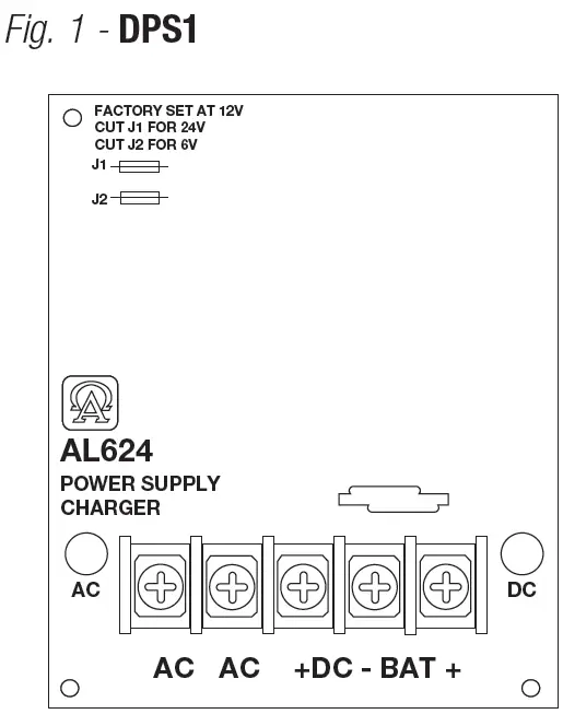
LED Diagnostics
| Red (DC) | Green (AC) | Power Supply Status |
| ON | ON | Normal operating condition. |
| ON | OFF | Loss of AC. Stand-by battery is supplying power. |
| OFF | ON | No DC output. Short circuit or thermal overload condition. |
| OFF | OFF | No DC output. Loss of AC. Discharged or no battery present. |
Terminal Identification
| Terminal Legend | Function/Description |
| AC/AC | Low voltage AC input (refer to Voltage Output/Transformer Selection Table). |
| + DC – | 6VDC-12VDC @ 1.2A continuous supply current. 24VDC @ 750mA continuous supply current. |
| – BAT + | Stand-by battery connections. Maximum charge rate 300mA. |
Altronix is not responsible for any typographical errors. 140 58th Street, Brooklyn, New York 11220 USA | phone: 718-567-8181 | fax: 718-567-9056 website: www.altronix.com.
e-mail: [email protected] | Lifetime Warranty. IIDPS1 – Rev. 091802 J22U.


