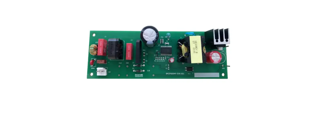
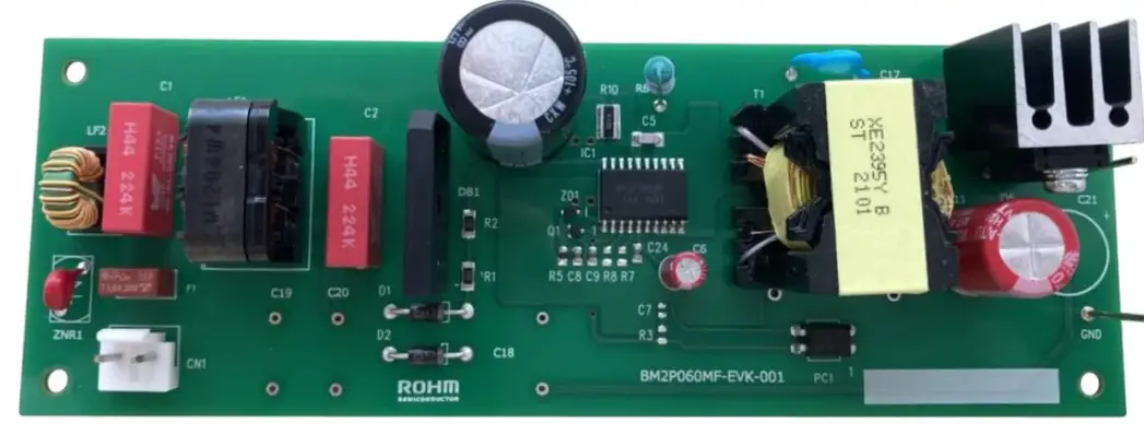
ROHM BM2P060MF-EVK-001 Isolation Fly-Back Converter PWM Method Output 40W 24V Evaluation Board
High Voltage Safety Precautions
Notice
- Read all safety precautions before use
- Please note that this document covers only the BM2P060MF evaluation board (BM2P060MF-EVK-001) and its functions. For additional information, please refer to the
- datashe et.
- To ensure safe operation, please carefully read all precautions before handling the evaluation board
- Depending on the configuration of the board and voltages used,
- Potentially lethal voltages may be generated.
- Therefore, please make sure to read and observe all safety precautions described in the red box below.
Before Use
- [1] Verify that the parts/components are not damaged or missing (i.e. due to the drops). [2] Check that there are no conductive foreign objects on the board. [3] Be careful
- when performing soldering on the module and/or evaluation board to ensure that solder
- splash does not occur. [4] Check that there is no condensation or water droplets on the circuit board.
During Use
- [5] Be careful to not allow conductive objects to come into contact with the board. [6] Brief accidental contact or even bringing your hand close to the board may result in
- discharge and lead to severe injury or death. Therefore, DO NOT touch the board with your bare hands or bring them too close to the board. In addition, as mentioned
- above please exercise extreme caution when using conductive tools such as tweezers and screwdrivers. [7] If used under conditions beyond its rated voltage, it may cause
- defects such as short-circuit or,
- depending on the circumstances, explosion or other permanent damages. [8] Be sure to wear insulated gloves when handling is required during operation.
After Use
- [9] The ROHM Evaluation Board contains the circuits which store the high voltage. Since it stores the charges even after the connected power circuits are cut, please
- discharge the electricity after using it, and please deal with it after confirming such electric discharge.
- [10] Protect against electric shocks by wearing insulated gloves when handling.
- This evaluation board is intended for use only in research and development facilities and should by handled only by qualified personnel familiar with all safety and operating
- procedures. We recommend carrying out operation in a safe environment that includes the use of high voltage signage at all entrances, safety interlocks, and protective
- glasses.
General Description
This evaluation board outputs an isolated voltage of 24 V from an input of 90 Vac to 264 Vac, and the maximum output current is 1.67 A. BM2P060MF which is PWM method DC/DC converter IC built-in 650 V MOSFET is used. Low on-resistance 0.7 650 V MOSFET built-in contributes to high efficiency (91 % typ). PWM controller for AC / DC power supplies, the BM2P060MF provides the optimum system for all products with outlets.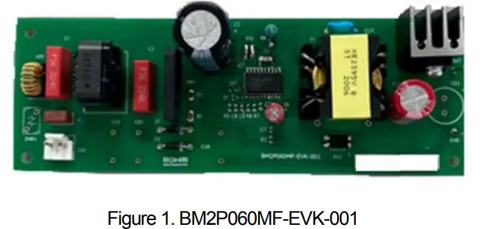
Performance Specification
Not guarantee the characteristics is representative value. Unless otherwise specified VIN = 230 Vac , IOUT = 1.67 A , Ta = 25 °C
| Parameter | Symbol | Min | Typ | Max | Units | Conditions |
| Input Voltage Range | VIN | 90 | 230 | 264 | V | |
| Input Frequency | fLINE | 47 | – | 63 | Hz | |
| Output Voltage | VOUT1 | 22.8 | 24.0 | 25.2 | V | |
| Output Current Range (Note1) | IOUT1 | 0 | – | 1.67 | A | |
| Maximum Output Power | POUT | 40.0 | W | |||
| Standby Input Power | PINSTBY | – | 47 | 100 | mW | IOUT = 0 A VIN = 230 V |
| Power supply efficiency | η | 88.0 | 91.0 | – | % | |
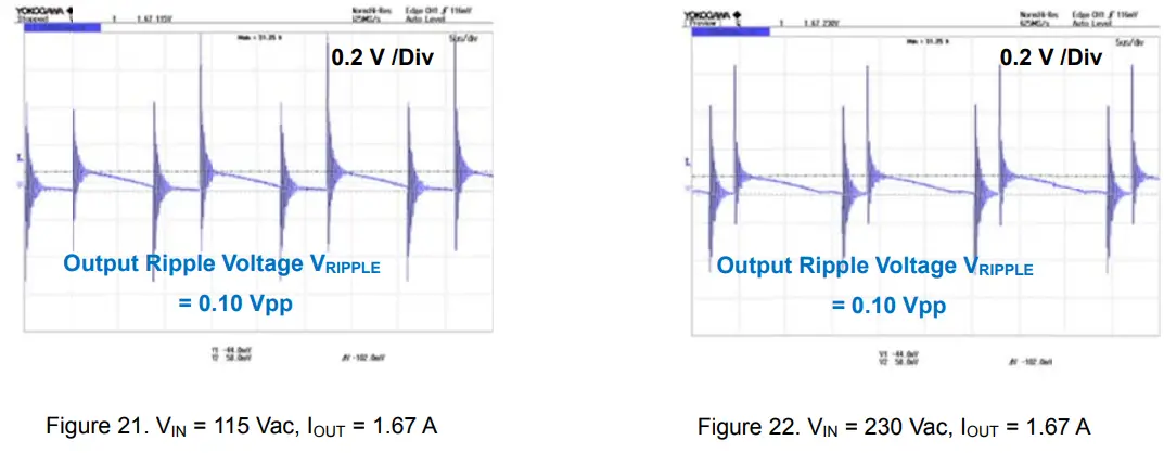
| Output Ripple Voltage (Note1) | VRIPPLE | – | 0.10 | 0.24 | Vpp | |
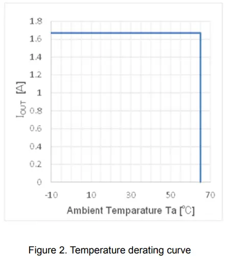
| Oprating Temperature | -10 | +25 | +65 | °C |
Derating
Operation Procedure
- Operation Equipment
- AC power supply (90 Vac to 264 Vac, 100 W or more)
- Load equipment (2 A at maximum value)
- DC voltmeter
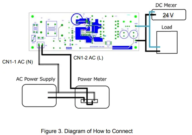
- Connect method
- Preset the AC power to 90 Vac to 264 Vac and turn off the power output. (
- Set the load below the rated current of each output to disable the load.
- Connect the N pin of the power supply to the CN1-1: AC (N) pin and the L pin to the CN1-2: AC (L) pin with a pair of wires.
- Connect each load to VOUT pin from the positive pin and to GND pin with a pair of wires.
- When connecting a power meter, connect as follows. (For details, refer to the User’s Manual of the electricity meter you are using.)
- Connect the positive pin of the DC voltmeter to VOUT pin and the negative pin to GND pin for output voltage measurement.
- AC power supply switch is ON.
- Make sure that the DC voltmeter reading is at the set voltage ( 24 V).
- Electronic load switch is ON.

Application Circuit
This evaluation board operates in flyback mode at a maximum frequency of around 65 kHz.. The output (24 V) voltage is monitored by a feedback circuit and fed back to the FB pin of BM2P060MF through a opto – coupler. At startup, the voltage at the VCC pin rises as the voltage is supplied from the DRAIN pin to the VCC pin through the start circuit. The demo board schematic is shown in Figure below and the list of parts is tabulated on page 13.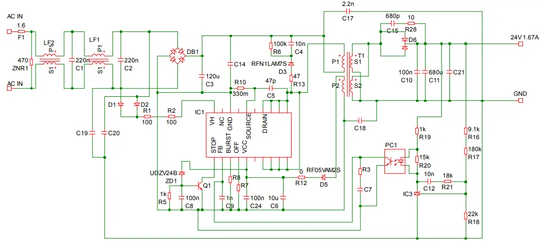
BM2P060MF General Description
Features
- AC Low Voltage Protection Function (AC UVLO)
- X Capacitor Discharge Function
- VCC Pin Low Voltage Protection (VCC UVLO)
- PWM Type Current Mode Control
- Frequency Reduction Function
- Burst Operation at Light Load External
- Burst voltage setting function
- Minimum ON width adjustment at light load
- Soft Start Function FB Pin Overload Protection
- Function (FB OLP) Over Current Protection Function by cycle
- Over Current Compensation by AC voltage detection.
- External Stop Function Dynamic
- Over Current Protection Leading Edge Blanking
- Pin Configuration
Key Specifications
- Operation Power Supply Voltage Range
- VCC Pin Voltage: 11 V to 60 V
- DRAIN Pin Voltage: 650 V (Max)
- Current at Switching Operation: 850 A (Typ)
- Current at Burst Operation 400 A (Typ)
- Switching Frequency 65 kHz (Typ)
- MOSFET ON Resistor 0.70 (Typ)
- Operation Temperature Range -40 °C to +105 °C
Package SOP20A
- W (Typ) x D (Typ) x H (Max) 12.8 mm x 10.3 mm x 2.65 mm
Applications
- AC Adapters, Each Household Applications and Power Supplies for Motor
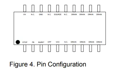
Pin Descriptions
| No. | Pin name | I/O | Function | No. | Pin name | I/O | Function |
| 1 | STOP | I | External stop pin | 11 | DRAIN | I/O | MOSFET Drain pin |
| 2 | FB | I/O | Feedback pin | 12 | DRAIN | I/O | MOSFET Drain pin |
| 3 | BURST | I | Burst setting pin | 13 | DRAIN | I/O | MOSFET Drain pin |
| 4 | OFF | I | MIN on setting pin | 14 | DRAIN | I/O | MOSFET Drain pin |
| 5 | VCC | I/O | Power supply input pin | 15 | N.C. | – | No connection |
| 6 | N.C. | – | No connection | 16 | SOURCE | I/O | MOSFET source pin |
| 7 | DRAIN | I/O | MOSFET Drain pin | 17 | N.C. | – | No connection |
| 8 | DRAIN | I/O | MOSFET Drain pin | 18 | GND | I/O | GND pin |
| 9 | DRAIN | I/O | MOSFET Drain pin | 19 | N.C. | – | No connection |
| 10 | DRAIN | I/O | MOSFET Drain pin | 20 | VH | I | AC voltage start-up pin |
Measurement Data
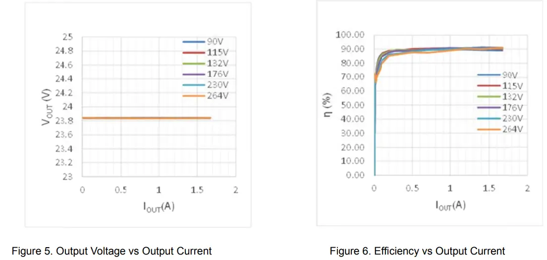
- Load Regulation

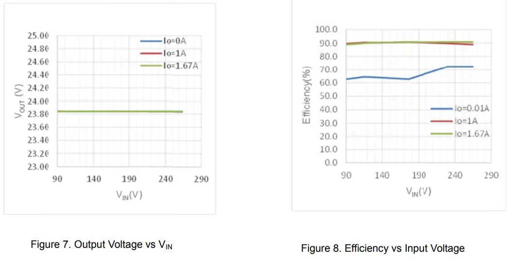
- Line Regulation

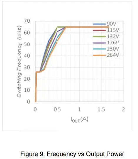
- Switching Frequency

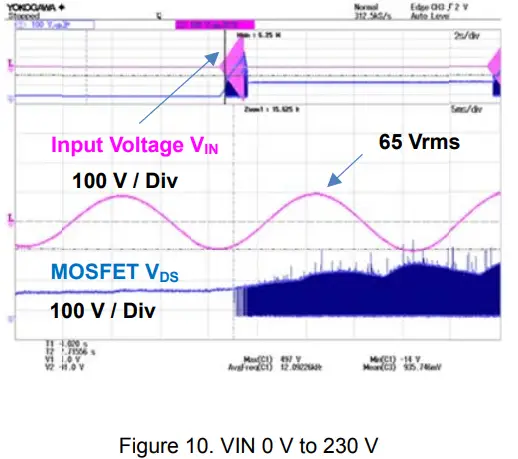
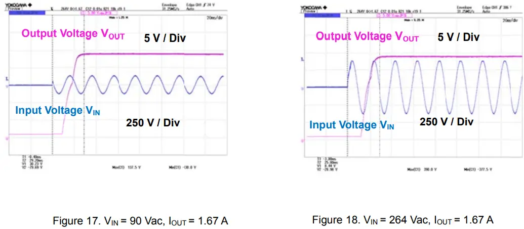
- Input Voltage Slowup

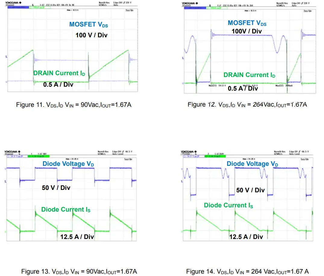
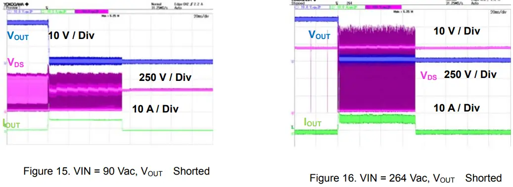
- Switching Wave Form


- Startup Wave Form

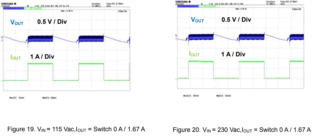
- Dynamic Load Fluctuation

- Output Voltage Ripple Wave Form

- Temperature of Parts Surface IOUT1
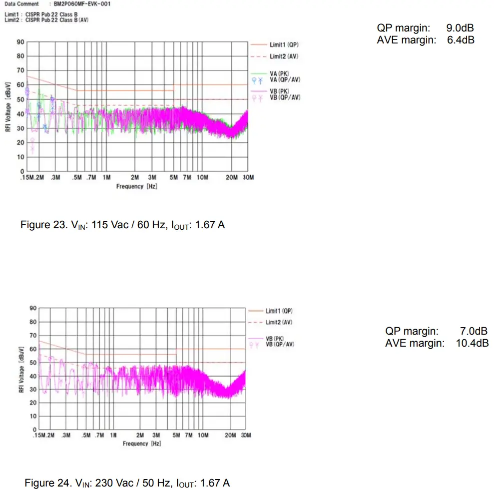
They are measured after 15 minutes from applying a power supply.Part Condition VIN = 90 ac, IOUT1 = 1.3 A VIN = 264 Vac, IOUT1 = 1.3 A IC1 60.4 °C 61.3 °C Diode D1 61.6 °C 62.3 °C - EMI Conducted Emission:CISPR22 Pub 22 Class B

Schematics
VIN = 90 Vac to 264 VacVOUT = 24 V 1.67 A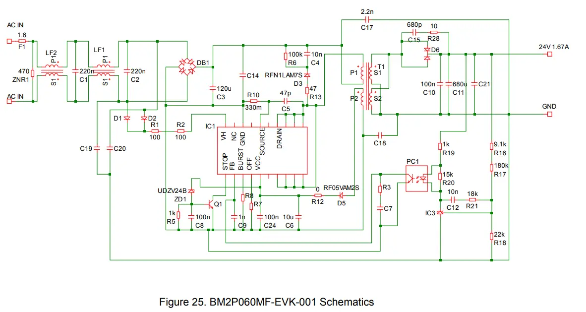
Parts List
| It m | Spec | Parts Nam | Manufacturer |
| C1,C2 | 20 n, 310 ac | 890334025027CS | WURTH |
| C3 | 20 µ, 450 V | 450CXW120MEFC18×31.5 | RUBYCON |
| C4 | 0 nF, 500 | 885342208009 | WURTH |
| C5 | 7 p, 630 V | GRM31A5C2J470JW01D | MURATA |
| C6 | 0 µF, 50 V | 860160672009 | WURTH |
| C7,C14,C1 ,C19,C20,C21 | on.mounted | ||
| C8,C10 C24 | .1 µF, 100 V | HM 107B7104 A-T | Taiyo Yuden |
| C9 | 000 pF, 100 V | HM 107B7102MA-T | Taiyo Yuden |
| C11 | 80 µF, 35 | 860080578019 | WURTH |
| C12 | .01 µF, 10 V | C0603C103K5RACTU | KEMET |
| C15 | 80 pF, 1 k | GRM31B5C2J681FW01L | MURATA |
| C17 | 200 pF, AC 300 V | DE1E3RA222MJ4BP01F | MURATA |
| D1,D2 | A, 1000 V | 1N4007 | |
| D3 | FRD, 0.8 A, 700 V | RF 1LAM7S | Rohm |
| D5 | FRD, 200 V, 0.5 A | RF05VAM2S | Rohm |
| D6 | FRD, 300 V, 20 A | RF2001T3D | Rohm |
| PC1 | LTV-817-B | Liteon | |
| Q1 | R, 50 V, 0.1 A | 2SCR523UB | Rohm |
| DB1 | 00 V, 4 A | D3 BA60 | S indengen |
| R1,R2 | 00 Ω | ESR18EZPJ101 | Rohm |
| R3,R7, 8 | on.mounted | – | Rohm |
| R5 | k | MC 03EZPJ10 | Rohm |
| R6 | 00 kΩ | MOS2CT52R104J | Rohm |
| R10 | 30 mΩ | LTR50EZPZFLR330 | Rohm |
| R12 | Ω | MC 18EZPJ00 | Rohm |
| R13 | 7 Ω | ESR18EZPJ470 | Rohm |
| R16 | .1 kΩ | MC 03EZPFX9101 | Rohm |
| R17 | 80 kΩ | MC 03EZPFX1803 | Rohm |
| R18 | 2 kΩ | MC 03EZPFX2202 | Rohm |
| R19 | kΩ | MC 03EZPJ10 | Rohm |
| R20 | 5 kΩ | MC 03EZPJ15 | Rohm |
| R21 | 8 kΩ | MC 03EZPJ18 | Rohm |
| R28 | 0 Ω | ESR18EZPJ100 | Rohm |
| F1 | .6 A, 300 | 36911600000 | ittelfuse |
| ZNR1 | 300 V, 400 A, φ 5 mm | V470ZA05P | ittelfuse |
| LF1 | 4.5 mH | SS 21NV-M12345 | TOKIN |
| LF2 | 0 µH | LF1246Y | アルファトランス |
| T1 | Q 26 | XE2395Y_B | アルファトランス |
| IC1 | BM P060MF | Rohm | |
| IC2 | on.mounted | ||
| IC3 | NC 431AVSNT1G | Onsemi | |
| ZD1 | 4V | UD VTE-1724 | Rohm |
| HEAT1 | 2.9 k/W | IC- 625-STL | |
| CN1 | B02P-NV(LF)(SN) | JST | |
| TP1,TP2 | CD-10-15 | MAC8 |
Layout
Size: 160 mm x 55 mm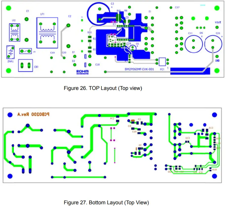
Specification of the Transformer
Manufacture
Alphatrans Co., Ltd. (1-7-2, Bakurou-cho, Chuo-ku, Osaka City, 541-0059, Japan)
Product Name: XE2395Y_B
Bobbin: 12PIN Core: PQ26
Primary Inductance: Withstand Voltage 500 H ±10 %
(100 kHz, 1 V)
Between Primary and Secondary: AC1500 V
Between Primary and Core: AC1500 V
Between Secondary and Core: AC500 V
Insulation Resistance 100 M or more (DC500 V)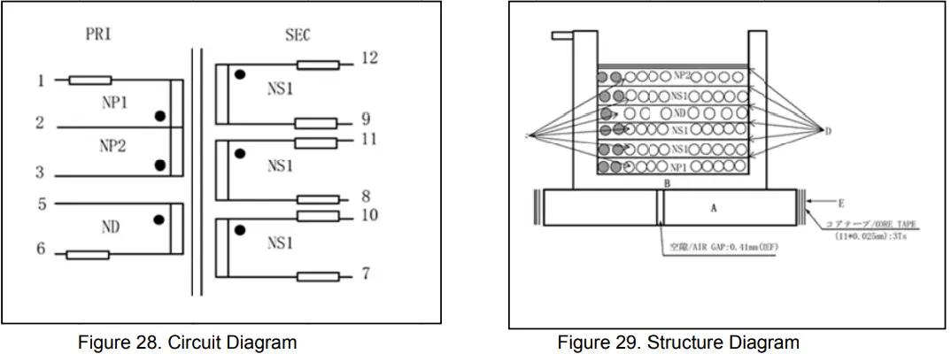
Table 2. Product Specification of XE2395Y_B
| No. | Transform r | Winding Pin | Wire | Turn Number | Tape Layer | Wire Specification | |
| Start | Finish | ||||||
| 1 | NP1 | 3 | 2 | 2UEW / Φ0.29 x 2 | 19 | 1 | COMPACT |
| 2 | NS1 | 10 | 7 | TEX / Φ0.32 x 2 | 11 | 1 | COMPACT |
| 3 | NS1 | 11 | 8 | TEX / Φ0.32 x 2 | 11 | 1 | COMPACT |
| 4 | ND | 5 | 6 | 2UEW / Φ0.15 x 1 | 8 | 1 | COMPACT |
| C5 | NS1 | 12 | 9 | TEX / Φ0.32 x 2 | 11 | 1 | COMPACT |
| 6 | NP2 | 2 | 1 | 2UEW / Φ0.29 x 2 | 19 | 3 | COMPACT |
Revision History
| Date | Rev. | Changes |
| 12.May.2021 | 001 | New Release |
Notice
- The information contained herein is subject to change without notice.
- Before you use our Products, please contact our sales representative and verify the latest specifications :
- Although ROHM is continuously working to improve product reliability and quality, semiconductors can break down and malfunction due to various factors. Therefore, in order to prevent personal injury or fire arising from failure, please take safety measures such as complying with the derating characteristics, implementing redundant and fire prevention designs, and utilizing backups and fail-safe procedures. ROHM shall have no responsibility for any damages arising out of the use of our Poducts beyond the rating specified by ROHM.
- Examples of application circuits, circuit constants and any other information contained herein are provided only to illustrate the standard usage and operations of the Products. The peripheral conditions must be taken into account when designing circuits for mass production.
- The technical information specified herein is intended only to show the typical functions of and examples of application circuits for the Products. ROHM does not grant you, explicitly or implicitly, any license to use or exercise intellectual property or other rights held by ROHM or any other parties. ROHM shall have no responsibility whatsoever for any dispute arising out of the use of such technical information.
- The Products specified in this document are not designed to be radiation tolerant.
- For use of our Products in applications requiring a high degree of reliability (as exemplified below), please contact and consult with a ROHM representative : transportation equipment (i.e. cars, ships, trains), primary communication equipment, traffic lights, fire/crime prevention, safety equipment, medical systems, servers, solar cells, and power transmission systems.
- Do not use our Products in applications requiring extremely high reliability, such as aerospace equipment, nuclear power control systems, and submarine repeaters.
- ROHM shall have no responsibility for any damages or injury arising from non-compliance with the recommended usage conditions and specifications contained herein.
- ROHM has used reasonable care to ensure the accuracy of the information contained in this document. However, ROHM does not warrants that such information is error-free, and ROHM shall have no responsibility for any damages arising from any inaccuracy or misprint of such information.
- Please use the Products in accordance with any applicable environmental laws and regulations, such as the RoHS Directive. For more details, including RoHS compatibility, please contact a ROHM sales office. ROHM shall have no responsibility for any damages or losses resulting non-compliance with any applicable laws or regulations.
- When providing our Products and technologies contained in this document to other countries, you must abide by the procedures and provisions stipulated in all applicable export laws and regulations, including without limitation the US Export Administration Regulations and the Foreign Exchange and Foreign Trade Act.
- This document, in part or in whole, may not be reprinted or reproduced without prior consent of ROHM.
Thank you for your accessing to ROHM product informations. More detail product informations and catalogs are available, please contact us.
ROHM Customer Support System
https://www.rohm.com/contact/
www.rohm.com © 2016 ROHM Co., Ltd. All rights reserved.


