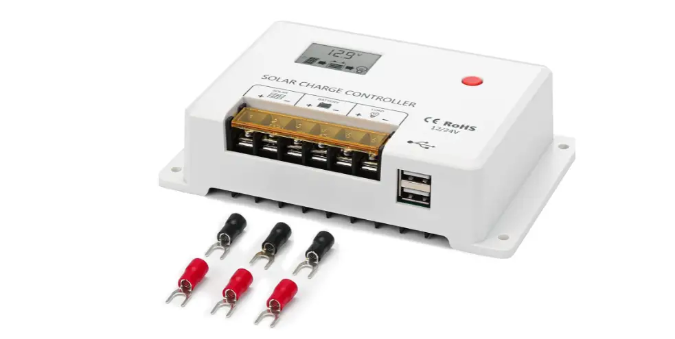
BougeRV HC24 Series PWM 24V Solar Charge Controller
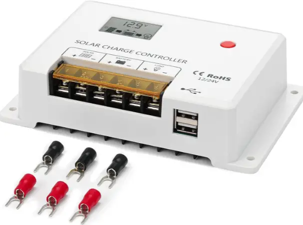
Unpack
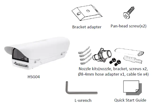
Note 1: Subject to modification. Actual products and accessories may differ in appearance.
Installation Notices
CAUTION:
INSTALLATION SHALL BE PERFORMED BY QUALIFIED PERSONNEL ONLY. INSTALLATION SHALL BE IN ACCORDANCE WITH LOCAL PROCEDURES. IT’S NOT RECOMMENDED TO USE WIPER WITHOUT A WASHER TANK. IT WILL CAUSE AN UNREPAIRABLE SCRATCH ON THE GLASS.
PLEASE APPLY APPROPRIATE PROTECTION TO THE EYES WHEN INSTALLING IR MODULE ON THE HOUSING.
Connectors
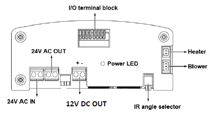
I/O Terminal Block Connection
| I/O | Description |
| DO2 | Connect to tank water pump. |
| DI2 | Wiper control, connects to IP camera’s DO for manually triggering washer. |
| RS485+ | Serial port to control IR, wiper and washer. |
| RS485- | |
| DO+ | +5V VCC |
| DI- | GND |
| DO1 | IR LED status, connect with camera input to control IR cut filter(default) |
| DI1 | IR control by camera |
TKH Security B.V. 2021 Vision 1.1 (20210218) HSG04 QSG
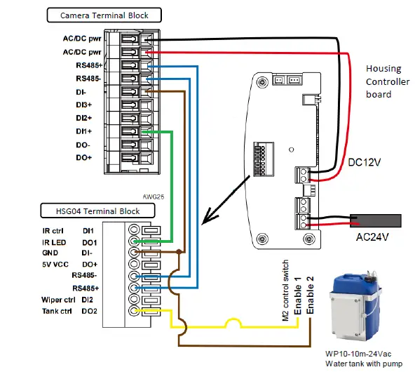
Connection diagram
RS485 Control
| protocol | Baud rate | data bits | parity | stop bit |
| Pelco-D | 2400 | 8 | None | 1 |
Pelco-D command
| Control | Pelco-D Command |
| Wiper On | Aux 1 On |
| Wiper Off | Aux 1 Off |
| Wiper and Washer On | Aux 2 On |
| Wiper and Washer Off | Aux 2 Off |
| IR Led Force On | Aux 3 On |
| IR Led Force Off | Aux 3 Off |
| HSG04-IR Wide | Zoom Wide |
| HSG04-IR Tele | Zoom Tele |
| HSG04-IR Stop | Zoom Stop |
Note 2: Once RS485 controls the IR Led, the IR mode will be in RS485 control. Please switch to “Light Sensor mode” by “FF 01 00 18 02 02 1D” Pelco-D command. The Light sensor at lamp will control the lamp by the lighting condition.
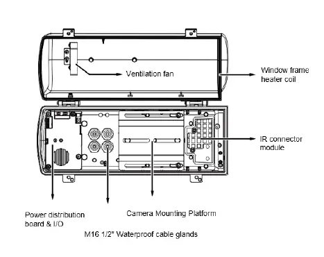
Complete HSG04 housing with accessories

Complete HSG04 housing with accessories
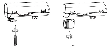
- Remove the metal cover from underneath the housing.
- 2. Install the HSG04-IR module and ensure the rubber gasket is in place.
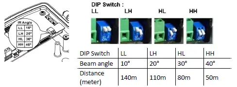
- Adjust the IR distance by DIP switch.

Optional Accessory – HSG04-Wall Mount
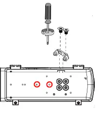
- Fasten 2 screws to secure the intersection bracket at the bottom of the housing.

- Install the housing by pressing the spring mortise and hooking the bracket onto the groove in the spring mortise. Fasten the screws on the side.

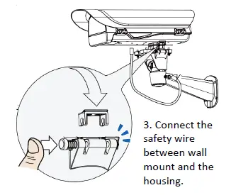
- Connect the safety wire between wall mount and the housing.
- Fasten the wall mount to the mounting holes as indicated above.
Optional Accessory – HSG04-Pole Mount
HSG04-pole mount can be used with HSG04-wall as well as HSG04-power box. The different mounting holes are indicated below.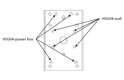
Optional Accessory – HSG04-Power Box
HSG04-Power box can be installed with HSG04-Wall as well as HSG04-Pole. The different mounting holes are indicated below.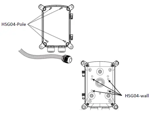
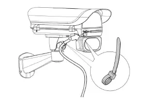
Optional Accessory –Water Tank, WP10-10m-24Vac
Install the washer nozzle with a bracket to the side of the HSG04. Connect a piece of Ø8mm hose to the nozzle and use an Ø8-4 hose adapter as the bridge to the hose included in WP10-10m-24Vac. Secure each connections with a cable tie.