ion4x Wi-Fi 6 2×2 Outdoor Access Point User Guide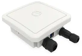
Introduction
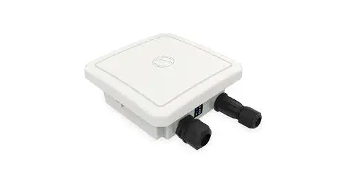
Thank you for purchasing our ion4x Access Point. ion4x is a cloud-managed 2×2:2 MU-MIMO Wi-Fi 6 certified Access Point that raises the bar for wireless performance and efficiency.
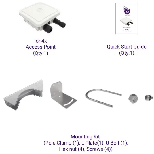
Packaging Content
ion 4x Specifications
| Peak Throughput(aggregate) | Up to 1.78 Gbps (1202 Mbps for 5 Gliz and 574 Mbps for 2.4 GHz) |
| VA-F1Standard Support | 802.11a/b/g/n/actec Wave 2/ax |
| Interface | 1 X 10/100/1000 BASET Ethernet |
| 1 X 2500 Base X Optical Ethernet SFP | |
| Radio Mode | 2×2 MU-MIMO wtth 2 spatial streams |
| Mesh Support | Self-creating. Self-heeling EasyMesh |
| Maximum number of SSID (per radio) | 16 |
| Maximum User Support | |
| 1024 clients per Access Pant (512 clients per radio) | |
| Power Supply | IEEE 802.3at PoE/PoE. |
| Power Consumption (Max) | 17 W (approx.) |
| Max Transmit Power | 30 d8m for 2.4 GHz .30 dam for 5614z (will depend on countrpspeafic guidelines) |
| Antenna Type | Integrated directional antennas with 90′ beamwidth |
| Antenna Gain | 8 OBI for 5 GH2.8 del for 2.4 Gitz |
| Management | Standalone (via GUI) or through on premise based solution or cloud-based |
| Enclosure Dimensions | 182 x 102 x 89 minor 7.17 x 7.17 x3.5 inches |
| Weight | 0.9 kg |
| Operating Temperature | -15’C to FOC |
| Certifications | FCC Class A, CE, Passpoir4 2.0, EasyMesh. WPM. IP67. MSS 3.0 |
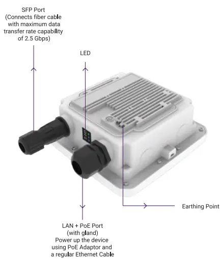
Product Overview
Mounting of ion4x Access Point
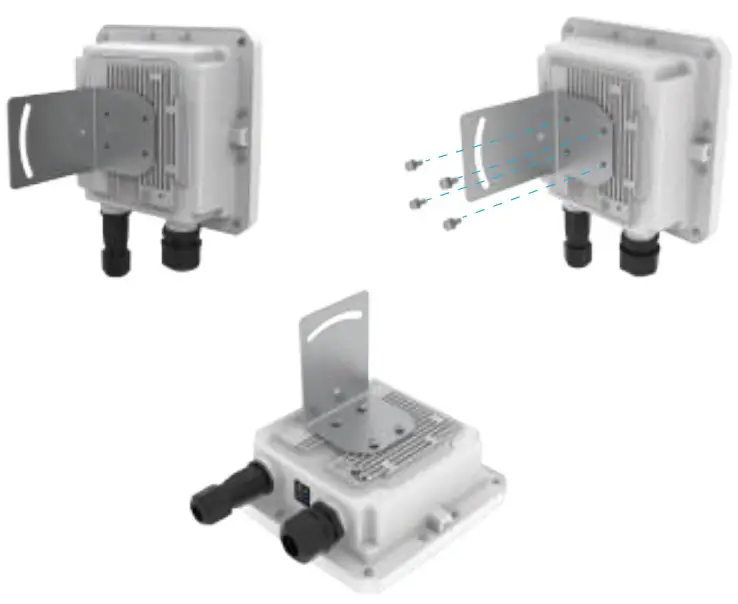
The ion4x can be mounted on a pole or to a wall. Perform the following steps for appropriate installation.
- Align L Plate with the holes at the back of Access Point
- Use the provided screws to fix the plate onto the Access Point. The mounting bracket is fixed onto the mounting holes on the Access Point

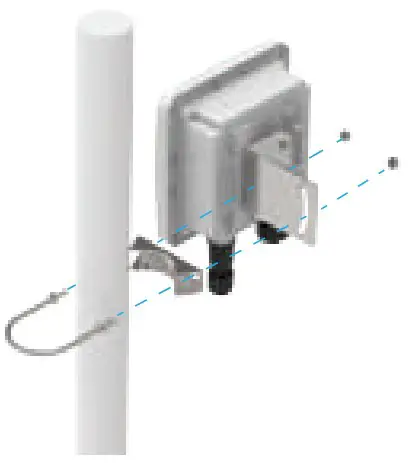
Pole Mount
- Align the L Plate mounted Access Point with pole clamp & U-Bolt
- Pass the U-Bolt through the cuts of pole clamp & L Plate.
Secure it in place with Hex Nuts.
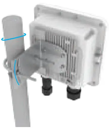
- Access Point has the freedom of movement along won the vertical horizontal axis

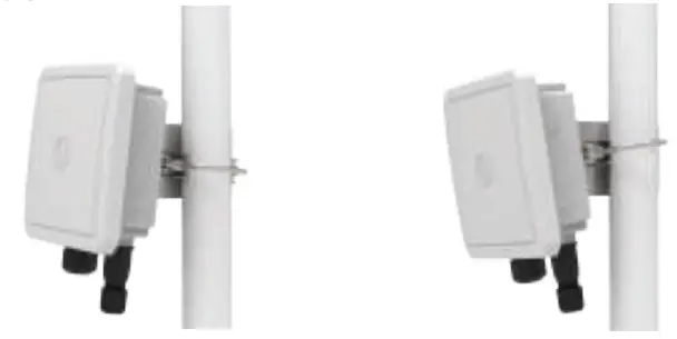
- The final alignment of Access Point on a pole mounting as shown below

Note: The pole mounting is designed for Kies of diameter 40 mm to 60 nvn. For mountings on larger size poles WO 140 mm. contact at [email protected]
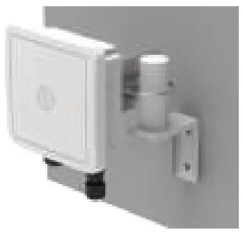
Wall Mount
To mount the ion4x on a wall, use the wall mounting bracket, drywall screws, and screw anchors (* The entire wall mounting assembly is sold seperately).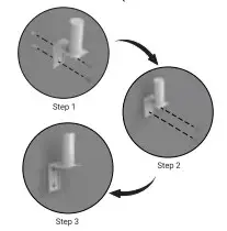
- Take the reference from the wall mounting bracket and mark the position of the holes on the wall.
- Use the drill machine to drill 2 holes on respective marked positions.
- Push the screw anchors into the holes with a hammer.
- Align the drilled holes with the holes of wall mounting bracket.
- Insert the drywall screws through the holes of mounting bracket into the wall.
- Wall mounting bracket is fixed to the wall.
- Mount the device on to the wall mounting bracket as discussed in pole mounting process.

WARNING: HFCL is not held liable for any damages incurred during the process.
Getting the ion4x Online
Step 1:Power up
The Access Point can be powered up u as shown below: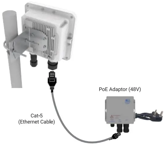
Note: Plug and Adaptor will vary by country/ region.
Power up using PoE Adaptor
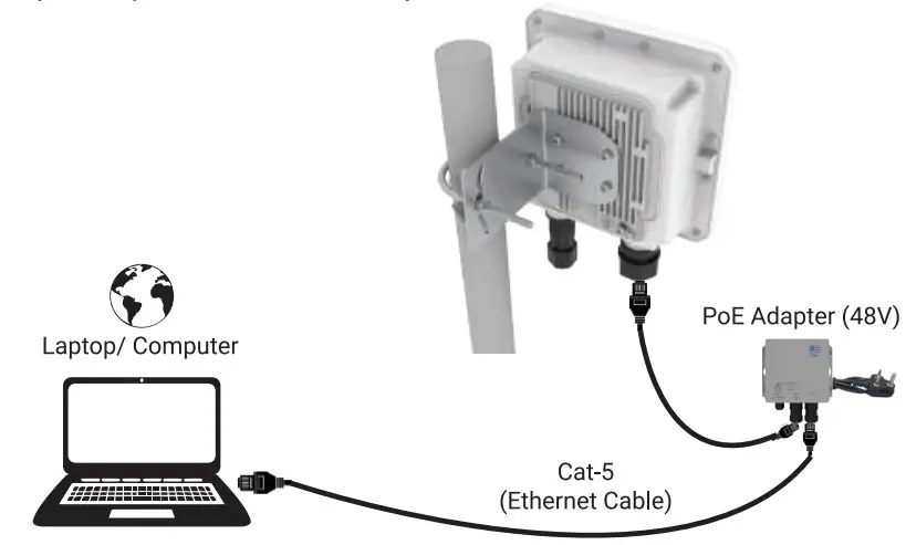
Step 2: Connect to the network
Section 1: Standalone
AP Follow the steps mentioned below and connect the Access Point to a network :
- Connect an ethernet cable to the computer.
- Connect the other end of ethernet cable to the data port on PoE adapter (48V)
- Connect ion4x PoE supported ethernet port to PoE adapter power port. Device will be powered on

- Configure the computer with a same domain static IP 192.168.1.X and a subnet mask of 255.255.255.0 (X is from 2 to 255)
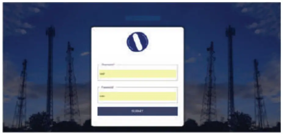
- Open the web browser and enter the Access Point static IP address in the address bar: 192.168.1.1
- A login screen will appear.
- Enter the default login credential details: User- root, Password- hfd!@ion

Section 2: Controller Managed AP
Follow the steps mentioned below and connect the Access Point to a network:
- Power-up the AP through PoE adapter or PoE switch
- Connect the AP to DHCP network and Internet
- Login to HFCL 10 cloud controller (cNMS) cnms.ionetworksin with credentials provided
- Refer our website io.hfd.com for detailed information to configure AP through cNMS
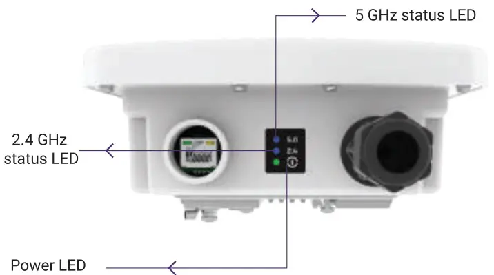
Step 3: Check the LED status
| LED Color | Status |
| Power LED Green | Green color notifies the user that the device is powered ON |
| 2.4 GHz Status LED | Solid blue color notifies the user that the 2.4 GHz radio is active and blinks while data is being transmitted on 2.4 GHz radio |
| 5 GHz Status LED | Solid blue color notifies the user that the 5 GHz radio is active and blinks while data is being transmitted on 5 GHz radio |
Safety Precautions
Observe the Idlowing safety precautions to avoid damage to the Jones Access Point:
![]() Do not power the device during In:Potation
Do not power the device during In:Potation![]() Keep away from high voltage cables
Keep away from high voltage cables![]() Do not power off the unit in the middle of an upgrade process
Do not power off the unit in the middle of an upgrade process![]() The gland should be ground lacing al the time
The gland should be ground lacing al the time![]() Do not open the enclosure
Do not open the enclosure![]() Fasten the device tightly
Fasten the device tightly![]() Make sure the earthing wire is connected properly to the earthing points.
Make sure the earthing wire is connected properly to the earthing points.
Contact Us:
Email: [email protected]
Website: www.hfcl.com
www.io.hfcl.com
8, Commercial Complex, Masjid Moth,
Greater Kailash-ll, New Delhi- 110048
HFCL Limited All Rights Reserved. 10 Networks and the IO logo are registered trademarks of HFCL Limited.
Specifications are subject to change without notice.


