
LCN 8310-2310 Touchless Actuator Battery Powered Contactless Switch

Description
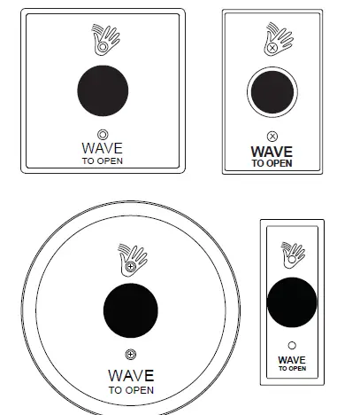
Available faceplates:
L Note: A minimum depth of 2-3/4” for all box installations, and mortised holes
- 8310-2310 (Single Gang): 2-3/4” x 4-1/2” stainless steel, fits on single gang electrical boxes.
- 8310-2320 (Double Gang): 4-1/2” x 4-1/2” stainless steel, fits on single gang or double gang boxes (required adapter plate included).
- 8310-2330 (Jamb Style): 1-3/4” x 4-1/2” stainless steel, has a custom mounting without a box. See the installation section below.
- 8310-2340 (Round): 6” Diameter, fits on single or double gang boxes (required adapter plate included).
Technical specifications
| Descriptions | 8310-2300 Series |
| Number of IR sensors | 1 |
| Batteries (supplied) | “AA” alkaline batteries |
| Estimated battery life | 2 years (based on 100 operations/day) |
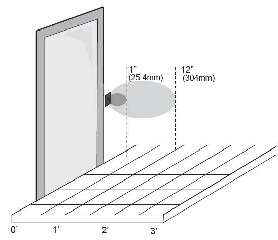
| Standard operating range | 1” – 12” (25.4mm – 304mm) Factory set to 6” (152mm) |
| Operating mode | Momentary Momentary with alarm |
| Inputs | “Request to Exit” external (door contact) input |
| Wireless output | Hard-wired transmitter |
| Relay output | 1 form “C” (SPDT) |
| Relay contact rating | 2 Amps @ 30 VDC |
| Output type | Normally Open or Normally Closed |
Installation
Mounting
The touchless actuator may be mounted in conventional 2-3/4” deep metal or plastic electrical gang boxes. Ensure that the unit sensor does not come in contact with the metal gang box to avoid shorting out the unit. Do not place the sensor in the door’s opening range, where the sensor may see door movement. Do not place moving objects in front of the sensor. Use the weather-resistant gasket as a protective barrier against the elements. For electrical box installation, refer to the instructions that come with the product.
NOTES: Plastic mounting boxes are required for use when using transmitters. A minimum depth of 2-3/4” for all box installations, and mortised holes when not using a box, is recommended. Actuators are recommended for interior use only!
Single gang electrical box (Single gang, double gang and round faceplates):
- If using an in-wall box ensure the box is plumb and square, and flush with the wall surface. If using a surface box, ensure it is secure & plumb.
- Bring your 2-conductor wire through the back or side of the enclosure and leave approximately 6” tail for wiring connection.
- Make the electrical connections to the device according to the wiring section (see Section 2).
- Using the dip switch located on the end of the unit, set the operating mode. (See Section 3.)
- Attach the unit to the enclosure using the two #6-32 screws provided.
- Attach the unit to the enclosure using the two #6-32 screws provided. #6-32 x 3/8 machine screws or tamperproof screws.
Note: Do not over-tighten!
Double gang electrical box (Double gang and round faceplate only):
- If using an in-wall box ensure the box is plumb and square, and flush with the wall surface. If using a surface box, ensure it is secure & plumb. If using a double-gang box, ensure the box is plumb and square with teh wall surface. Then attach the metal adapter plate provided in the packaging.
- Bring your 2-conductor wire through the back or side of the enclosure and leave approximately 6” tail for wiring connection.
- Make the electrical connections to the device according to the wiring section (See Section 2).
- Using the dip switch located on the end of the unit, set the operating mode. (See Section 3)
- Attach the unit to the enclosure using the two #6-32 screws provided.
- Attach the faceplate to the unit using the two black #6-32 x 3/8 machine screws or tamperproof screws.
Note: Do not over-tighten!
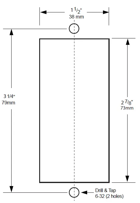
Jamb mount (Jamb faceplate only):
Note: A minimum depth of 2-3/4” for all box installations, and mortised holes when not using a box, is recommended.
- If mounting directly in a 1-3/4” wide aluminum jamb, make a cutout in the door frame at the intended location. Drill and tap two mounting holes as shown.
- Bring your 2-conductor wire through the back or side of the enclosure and leave approximately 6” tail for wiring connection.
- Make the electrical connections to the device according to the wiring section (see Section 2).
- Using the dip switch located on the end of the unit, set the operating mode. (See Section 3)
- Attach the unit to the enclosure or jamb using the two #6-32 screws provided.
- Attach the faceplate to the unit using the two black #6-32 x 3/8 machine screws or tamperproof screws.
Note: Do not over-tighten!
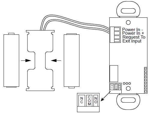
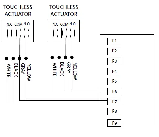
Wiring
CAUTION:
Do not apply power to the unit until all secondary wiring is complete, and dip-switches have been set.
The actuator is powered from 2 AA batteries (supplied). The battery holder has been pre-installed. Insert the batteries into the battery holder. Please be careful that the polarity of the batteries is correct.
The actuator output is a form “C” relay. Selecting the correct output is also dependent on the operating mode chosen. Most applications will utilize the N.O. and Common terminals.
Set-up
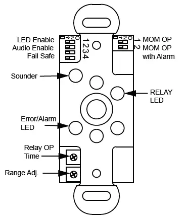
Dip Switch Settings
See the diagrams below for the dip switch locations:
| Dip Switch Bank 1 | ||
| 8310-2300 Series | Description | |
| 1 | LED Enable | Green LED flashes while the output is activated |
| 2 | Audio Enable | Piezo buzzer sounds when the output is activated |
| 3 | Normally Open/Closed Mode | Changes the output relay logic. N/O becomes N/C and N/C becomes N/O. |
| 4 | Toggle Mode | Relay toggles on each activation. |
| Dip Switch Bank 2 | |||
| Function | SW1 | SW2 | Description |
| Momentary | OFF | OFF | The output operates once and only re- engages after the object is removed. |
| Momentary with alarm | ON | OFF | The output operates once, and only re- engages after the object is removed. If an object remains in the detectable area, an alarm will generate after about 30 seconds. |
| Continuous operation | OFF | ON | The output remains activated until the object is removed. |
Switch 1 – LED On/LED Off
This switch disables the LED, should this feature be desired. The factory setting is OFF. This feature will decrease the battery life if set to ON.
Switch 2 – Audio Enable:
Set this switch to ON to enable an audible beep every time the switch is activated. The factory default is OFF. Enabling this feature will use additional power and decrease the life of the battery.
Switch 2 – Audio Enable
For LCN applications, choose Normally Open mode if you want the N.O. contact to remain open if the power were to fail. The dip switch in the OFF position is the factory setting.
Switch 4 – Toggle mode”
The relay will activate and stay activated until the object is removed and then presented again.
Battery strength meter
To check the battery strength, place an object in front of the actuator for about 5 seconds. The actuator will beep up to five times, indicating the batter charge level. Five beeps will mean that the battery is fully charged. One to three beeps will mean that you should change the batteries.
Adjustments
Once the dip switches have been set, and the unit is installed in the frame or enclosure, apply power to the unit and observe the operation. Set both potentiometers to minimum setting initially (fully counter-clockwise).
Adjust the range potentiometer by turning the pot in a clockwise manner, and passing your hand in front of the unit. Rotate the pot until the desired range is obtained. See the diagram on the previous page for locations.
Next, adjust the time delay potentiometer by turning clockwise until the desired time delay is obtained. It is sometimes beneficial to leave this adjustment set to a minimum and utilize the time delay on the door operator if present.
Troubleshooting
| Door does not open when swiping hand in front of sensor | Bad or no power | Check power supply. If LED switches on or flashes, power connections are okay. |
| Check battery strength (check battery strength meter). Remove & replace batteries. Replace faulty actuator assembly. | ||
| Detection range too short | Adjust detection zone. Remove any metal plates in front of sensor. | |
| Incorrect wiring/connection | Check wiring and relay connection. | |
| Sensor stays in detection | Environmental conditions influencing sensor | Remove moving objects from around sensor. |
| Incorrect wiring/connection | Check wiring and relay connection. | |
| Door remains open after detection/ activation | Wrong output mode | Switch output mode to Pulse. |
| Incorrect wiring/connection | Check wiring and relay connection. | |
| No activation | Power wires not connected | Verify power connect at actuator touchless plate, and power source. |
| Activation wires not connected | Verify activation connection at actuator and door control. | |
| Constant activation | Something is moving in front of the touchless plate | Actuator alarm will sound.Verify DIP positions SW1 (ON) & SW2 (OFF).
Clear the area around the plate. |
| Transmitter or connected activation wires are connected to NC of touchless sensor | Ensure that DIP 3 is set to OFF (N.O.). Make sure the activation wires are connected to N.O. | |
| Touchless sensor set to Toggle Mode | Turn DIP 4 in Bank 1 to OFF. |
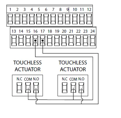
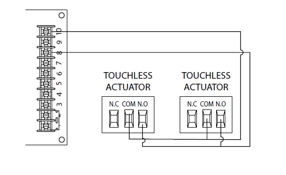
Wiring diagrams
4630/4640 Series Electric Auto-Equalizer
7900 Series
Pneumatic Auto-Equalizer
9100 Series Benchmark
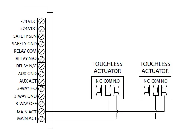
2800/9500 Series Senior Swing
Do not leave problems unresolved. If a satisfactory solution cannot be achieved after troubleshooting a problem, please contact Allegion at 1-877-671-7011. If you must wait for the following work day to call Allegion, leave the door inoperable until satisfactory repairs can be made. Never sacrifice the safe operation of the automatic door or gate for an incomplete solution.
For more information, visit www.allegion.com
© Allegion 2021 Printed in U.S.A. 47375847 Rev. 03/21-a


