![]() DRY700 Smart Dry Contact Switch 7
DRY700 Smart Dry Contact Switch 7
Instruction Manual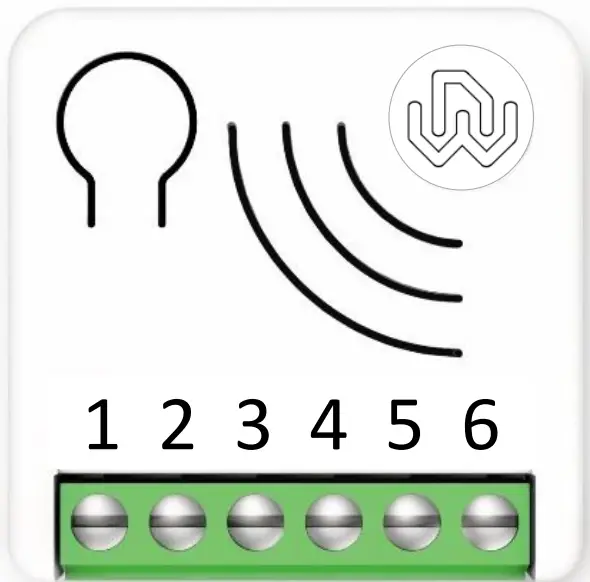 Smart Dry Contact Switch 7
DRY700 Operating instructions ![]()
Revision History
Rev. Doc. | Date | Page | Description |
| 0 | 14/03/2022 | Initial version |
Device description
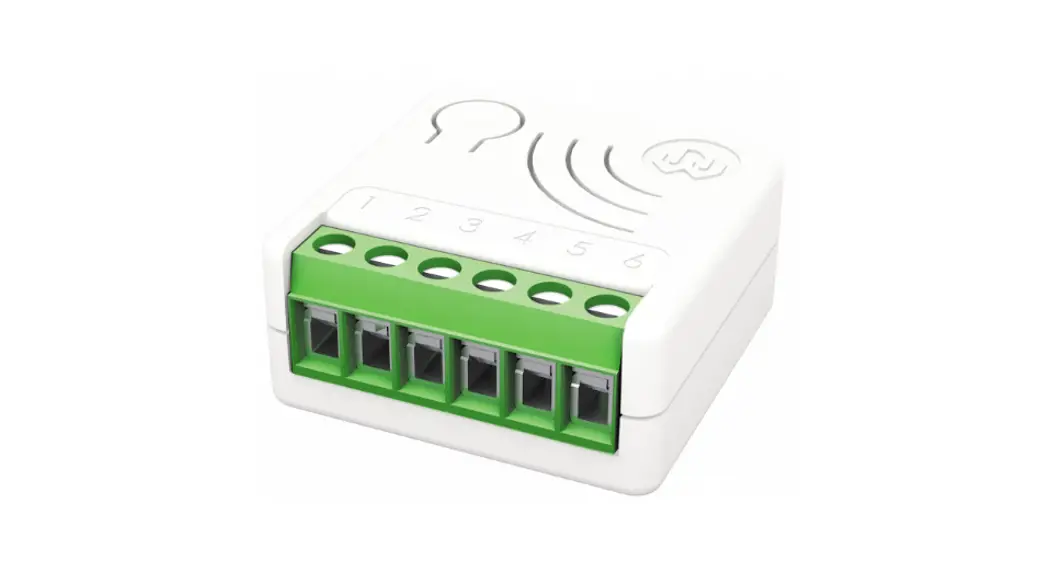
Smart Dry Contact Switch 7 can turn ON and OFF equipment’s with an independent power supply, such as solenoid valves (e.g. gas, water and irrigation), power operated valves etc.
It is very easy to install and works with both momentary and toggle switches.
It operates in any Z-Wave™ network with other Z-Wave™/Z-Wave Plus™ certified devices and controllers from any other manufacturer. As a constantly powered node, the device will act as repeater regardless of the vendor in order to increase the reliability of the network.
This device is a security enabled Z-Wave Plus™ product that is able to use encrypted Z-Wave Plus™ messages to communicate to other security enabled Z-Wave Plus™ products.
This device must be used in conjunction with a Security Enabled Z-Wave™ Controller in order to fully utilize all implemented functions.
The device has the unique feature Offline setup Mode that allows to configure some parameters without using any user interface. This feature enables the professional user to setup the main features of the device in the field even if the device is not included in a Z-Wave™ Network. When the device will be included in the network all these configuration parameters will be maintained. 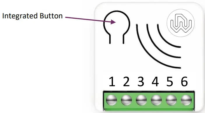
| Integrated Button | 1 or 3 clicks to enter in Learn Mode 6 clicks to reset the system to manufacturer’s settings 2 clicks to enter in Offline setup mode |
| Power Supply | 1, 2 – Null 6 – Line |
| Input Switch | 3 – Input – Line signal |
| Output | 4, 5 – Dry Contact |
Technical Specifications
| Power supply | 110 – 230 VAC±10% 50/60 Hz – 24VDC |
| Maximum Load on Relay | 16A resistive Load |
| System temperature limitation | 105°C |
| Work temperature | From -10° to 40° C |
| Power consumption | < 260 mW in standby < 480 mW with working load |
| Radio frequency | 868.4 MHz |
| Protection system | S2 Security |
| Maximum distance | Up to 100 m outdoor Up to 40 m indoor |
| Dimensions | 37x37x17 mm |
| Actuator element | 16 Amp relay |
| Compliance | CE, RoHs |
| Electrical IP Rating | IP20 |
Safety information
![]() INFO: The device is designed to be installed in flush mounting junction boxes or close to the load to be controlled.
INFO: The device is designed to be installed in flush mounting junction boxes or close to the load to be controlled.![]() WARNING: The device must be installed by electricians qualified to intervene on electrical systems in compliance with safety requirements set out by the regulations in force.
WARNING: The device must be installed by electricians qualified to intervene on electrical systems in compliance with safety requirements set out by the regulations in force.![]() DANGER The device must be connected with a voltage of 230 VAC, before carrying out any operation, please make sure the power main switch is in OFF position.
DANGER The device must be connected with a voltage of 230 VAC, before carrying out any operation, please make sure the power main switch is in OFF position.![]() DANGER: Any procedure requiring the use of the Integrated Button is related only to the installation phase and is to be considered a service procedure that must be performed by qualified personnel. This operation must be performed with all necessary precautions for operating in areas with a single level of insulation.
DANGER: Any procedure requiring the use of the Integrated Button is related only to the installation phase and is to be considered a service procedure that must be performed by qualified personnel. This operation must be performed with all necessary precautions for operating in areas with a single level of insulation.![]() WARNING: Do not connect loads that exceed the maximum load permitted by the actuator element.
WARNING: Do not connect loads that exceed the maximum load permitted by the actuator element.![]() WARNING: All connections must be performed according to the electrical diagrams provided
WARNING: All connections must be performed according to the electrical diagrams provided![]() WARNING: The device must be installed in norm-compliant systems suitably protected from overloads and short circuits.
WARNING: The device must be installed in norm-compliant systems suitably protected from overloads and short circuits.
Electrical Connections diagram
The device must be supplied by 230 AC or by 24 VDC Power Supply
Connections must be done following one of the diagrams below: if you need to control a Load connected on a different power supply system you must follow the diagram on the right side.
| Controlling a Load connected to the same power supply system | Controlling a Load connected to an independent power supply system |
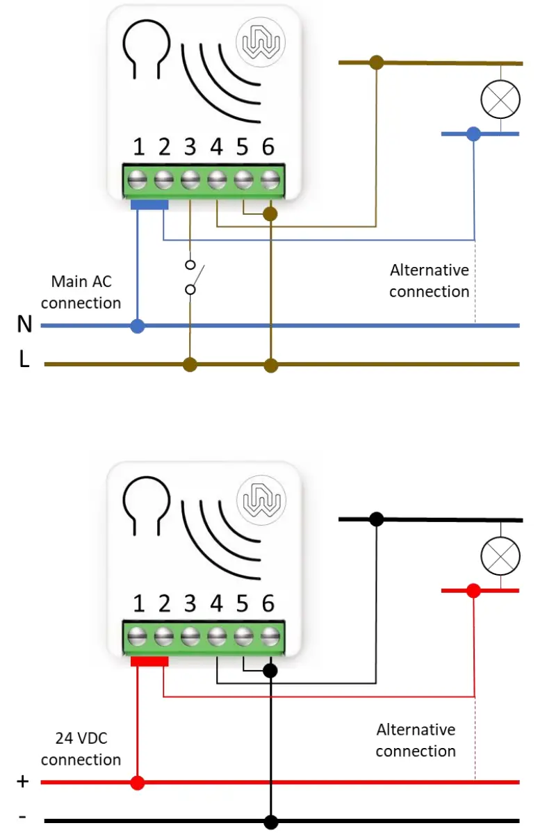 | 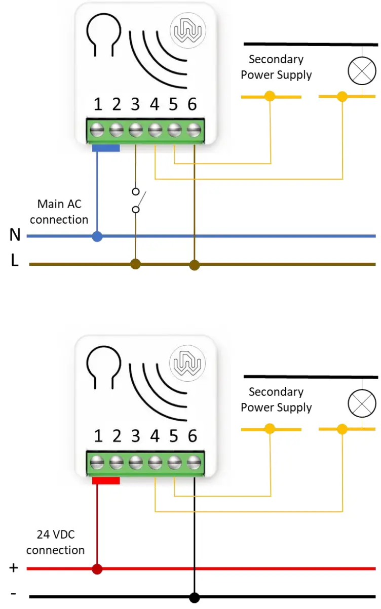 |
| Power Supply | 1, 2 – Null 6 – Line |
| Input Switch | 3 – Input – Line signal |
| Output | 4, 5 – Dry Contact |
![]() WARNING: The power line must be opportunely protected from short-circuits and excess load due to a failure of the load
WARNING: The power line must be opportunely protected from short-circuits and excess load due to a failure of the load
Device Installation
- Make sure the main switch is set to the OFF position
- Connect the device based on the diagrams provided
- Turn the main switch to the ON position
- Include the device in the Z-Wave™ network
![]() TIP: The antenna must not be shortened, removed or modified. To ensure maximum efficiency, it must be installed as shown. Large size metal equipment near the antenna can negatively affect reception. Each device is a node in a mesh network. If there are metal obstacles, the obstacle can often be overcome with a further triangulation node.
TIP: The antenna must not be shortened, removed or modified. To ensure maximum efficiency, it must be installed as shown. Large size metal equipment near the antenna can negatively affect reception. Each device is a node in a mesh network. If there are metal obstacles, the obstacle can often be overcome with a further triangulation node.
LED status indicator
The system includes an RGB LED that shows the device’s status during installation:
Solid RED: the device is not included in any network
Solid BLUE: the device is Offline setup mode state
4 GREEN blinks then OFF: the device has been just added to a Z-Wave™ network in S2 Authenticate Mode
4 BLUE blinks then OFF: the device has been just added to a Z-Wave™ network in S2 Unauthenticated Mode
4 RED blinks then OFF: the device has been just added to a Z-Wave™ network without security
Sequence of GREEN-BLUE Learn Mode for inclusion
Sequence of RED-BLUE Learn Mode for exclusion
Rapid sequence of GREEN-BLUE-RED: the event on the input (external switch) is not valid![]() TIP: To test if the electrical connections are correct, before the inclusion of the device, while pressing n times the external switch, the RGB LED should flash green for the same amount of times. If it does not, check the wire connections.
TIP: To test if the electrical connections are correct, before the inclusion of the device, while pressing n times the external switch, the RGB LED should flash green for the same amount of times. If it does not, check the wire connections.
Add/Remove the device into a Z-Wave™ network (classic)
Standard Inclusion (add)
All Smart Serie 7 devices are compatible with all Z-Wave™/Z-Wave Plus™ certified controllers. The devices support both the Network Wide Inclusion mechanism (which offers the ability to be included in a network, even if the device is not directly connected to the controller) and Normal Inclusion.
By default, the inclusion procedure starts in Normal Inclusion mode and after a short timeout the procedure continues in Network Wide Inclusion mode that lasts for about 20 Seconds.
Only a controller can add the device into the network. After activating the inclusion function by the controller, the device can be added by setting it in Learn Mode.
Before including the device, the LED status indicator is solid RED. The adding of a device is executed by activating the adding procedure in the inclusion section of the controller interface and executing 1 or 3 click on the integrated button (the device is set in Learn Mode). As soon as the inclusion procedure initiates the LED indicator starts a sequence of GREEN-BLUE blinks. The device is included in the network when the LED status is OFF and the interview is completed.
Standard exclusion (remove)
Only a controller can remove the device from the network. After activating the exclusion function by the controller, the device can be removed by setting it in Learn Mode.
The procedure of exclusion can be activated by Removing a node from the Z-Wave™ network and executing 1 or 3 click on the integrated button; as soon as the exclusion initiates, the LED indicator starts a sequence of RED-BLUE blinks. The device is excluded from the network when the LED status indicator is solid RED and the App_status in the interface is OK.
SmartStart Inclusion
Z-Wave™ SmartStart aims to shift the tasks related to inclusion of an end device into a Z-Wave™ network away from the end device itself, and towards the more user-friendly interface of the gateway.
Z-Wave™ SmartStart removes the need for initiating the end device to start inclusion. Inclusion is initiated automatically on power-ON and repeated at dynamic intervals for as long as the device is not included into a Z-Wave™ network. As the new device announces itself on power-ON, the protocol will provide notifications, and the gateway can initiate the inclusion process in the background, without the need for user interaction or any interruption of normal operation. The SmartStart inclusion process only includes authenticated devices.
Smart Serie 7 devices can be added into a Z-Wave™ network by scanning the Z-Wave™ QR Code present on the product with a controller providing SmartStart inclusion. No further action is required and the SmartStart product will be added automatically within 10 minutes of being switched on in the network vicinity.
The SmartStart QR and the full DSK string code can be found on the back of the device. The PIN is the first group of 5 digits printed underlined. If you plan to use the DSK, it is important that you take a picture of the label and keep it in a safe place.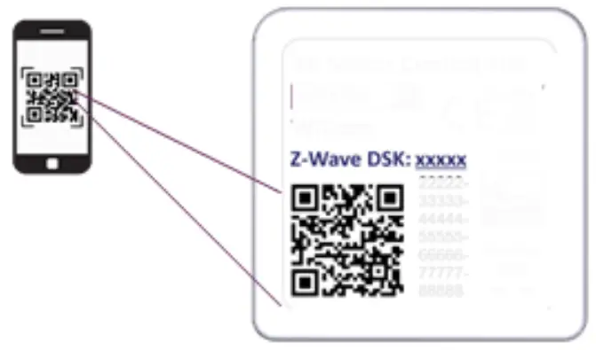
S2 Secure inclusion
When adding Smart Serie 7 devices to a Z-Wave™ network with a controller supporting Security 2 Authenticated (S2), the PIN code of the Z-Wave™ Device Specific Key (DSK) is required. The unique DSK code is printed on the product label. The first five digits of the key are highlighted and underlined to help the user identify the PIN code.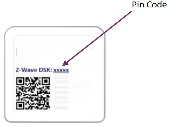
Supported Command Classes
| Command Class | Version | Non-Secure CC | Secure CC |
| BASIC | 2 | x | |
| ZWAVEPLUS_INFO | 2 | x | |
| ASSOCIATION | 2 | x | |
| MULTI_CHANNEL_ASSOCIATION | 3 | x | |
| ASSOCIATION_GRP_INFO | 3 | x | |
| TRANSPORT_SERVICE | 2 | x | |
| VERSION | 3 | x | |
| MANUFACTURER_SPECIFIC | 2 | x | |
| DEVICE_RESET_LOCALLY | 1 | x | |
| INDICATOR | 3 | x | |
| POWERLEVEL | 1 | x | |
| SECURITY_2 | 1 | x | |
| SUPERVISION | 1 | x | |
| FIRMWARE_UPDATE_MD | 5 | x | |
| APPLICATION_STATUS | 1 | x | |
| CONFIGURATION_V4 | 4 | x | |
| SWITCH_BINARY | 2 | x | |
| CENTRAL_SCENE | 3 | x |
Supporting Command Class Basic
The basic command classes are mapped into the Switch Binary Command Class.
| Basic Command received | Mapped Command (Binary Switch) |
| Basic Set (0xFF) | Switch Binary Set (0xFF) |
| Basic Set (0x00) | Switch Binary Set (0x00) |
| Basic GET | Basic Report 0x00 if the Binary Switch is in Off state 0x00 Basic Report 0xFF if the Binary Switch is in On state 0xFF |
Supporting Command Class Indicator
The device supports the Command Class Indicator V3 (ID 0x50). When the device receives an indicator set, the led blinks accordingly to the Indicator set received.
The color shown by the indicator will be:
RED: if the device is included without Security
BLUE: if the device is included in S2 Unauthenticated Mode
GREEN: if the device is already included in S2 Authenticated Mode
Device Control
Smart Dry Contact Switch 7 can turn ON and OFF the load by using an external switch, or from remote through a controller.
Controlling the device by External Switches
For the operation of the device within the Z-Wave™ network and controlling the loads connected to the device, control actions are performed on the external switches.![]() The CONTROL ACTIONS are EVENTS executed on EXTERNAL SWITCHES connected to the Line Signal terminal of the device which can be Clicks, Hold Down and Up.
The CONTROL ACTIONS are EVENTS executed on EXTERNAL SWITCHES connected to the Line Signal terminal of the device which can be Clicks, Hold Down and Up.
| Event | Type of switch | Actions on the switch |
| Click | Momentary switch (button) | Press briefly & Release (when pressed it autonomously returns to the initial position) |
| Toggle Switch (bistabile) | Press & Release (a single click means one single flip of the switch) | |
| MultiClick=n clicks | Momentary switch | Sequence of consecutive n clicks |
| Toggle Switch | ||
| Hold Down | Momentary switch | Press longer than click. After a Hold Down always follows an UP event. |
| Up | Momentary switch | Release. The event applies only if there has been a previous Hold Down event. |
Since the device supports Central Scene Notification all the events described in the table will be notified with a Central Scene Notification Report to the Lifeline. The events that trigger a Central Scene Notification Report can be customized with the configuration parameter in the Central Scene Notification Parameter section.
Controlling the device by a Z-Wave™ controller
The device can be controlled by any Z-Wave™ / Z-Wave Plus™ certified controller available in the market.
In the figure below, are represented a couple of examples of control panel interfaces that show how the device will appear once included into the Gateway.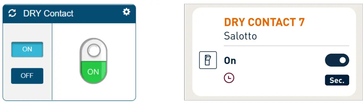
Associations
Smart Dry Contact Switch 7 can control other devices like other relays or dimmers. The device supports 5 association groups, each of which supports the association of up to 8 devices (nodes):
| Group ID | Group Name | N° of max nodessupported in the group | Description | Command sent |
| 1 | Lifeline | 8 | LifeLine Group. Nodes belonging to this group will receive: notifications about device reset; changes related to the relay and Indicator Status and the Central Scene Notification. | DEVICE_RESET_LOCALLY_NOTIFIC ATIONS WITCH_BINARY_REPORT CENTRAL_SCENE_NOTIFICATION INDICATOR_REPORT |
| 2 | Follow me | 8 | The state of the output (ON/OFF) will be propagated to the associated device. | BASIC_SET |
| 3 | clicks on button 1 G1 | 8 | The associated device will be controlled based on the click events and output propagation defined by configuration parameters on the Association group management section | |
| 4 | clicks on button 1 G2 | 8 | ||
| 5 | Dimming Group | 8 | The devices will be controlled by dimming commands: 1 ClickàON/OFF 2 ClicksàMax On Level Hold Downà change level in UP/Down direction UP àStop level Change | SWITCH_MULTILEVEL_SET SWITCH_MULTILEVEL STOP_LEVEL_CHANGE |
![]() INFO: Association ensures direct transfer of control commands between devices and is performed without participation of the main controller.
INFO: Association ensures direct transfer of control commands between devices and is performed without participation of the main controller.
Timer Management
A timer can be set when switching On and/or Off. It is also possible to define which event will start the timer. (for example only the change on the output due to double clicks).
Reset to the factory settings
The device can be reset to the original factory settings with 6 consecutive clicks on the integrated button. After the reset is completed, the device will reboot and a RED solid led is showed.
Please use this procedure only when the network primary controller is missing or otherwise inoperable.![]() INFO: If the reset is performed while the device is still part of a network, it notifies the other devices that it has been removed (Device Reset Locally Notification).
INFO: If the reset is performed while the device is still part of a network, it notifies the other devices that it has been removed (Device Reset Locally Notification).
Firmware Update
The system supports over-the-air firmware updates that do not require the device to be removed from its location. The firmware update can be activated from all certified controllers supporting version 2 of the Firmware Update function.![]() WARNING: The system will be rebooted at the end of the firmware update procedure. It is advisable to carry out the firmware update procedure only when necessary and following careful planning of the intervention.
WARNING: The system will be rebooted at the end of the firmware update procedure. It is advisable to carry out the firmware update procedure only when necessary and following careful planning of the intervention.
Offline setup Mode
The device has a unique feature that allows to configure some parameters without using any user interface. This feature enables the professional user to setup the main features of the device in the field even if the device is not included in a Z-Wave™ Network. When the device will be included in the network all these configuration parameters will be maintained.
To enter in offline setup mode, operate 2 clicks on the integrated button.
When the device is in Offline setup mode the led becomes solid Blue and the following configurations are permitted:
| 1 click | Setup input type to toggle switch. Equivalent to set parameter n.1 to 2 |
| 2 clicks | Activate a switch Off timer of 10 minutes. Equivalent to set parameter n.30 to 15 and parameter n.31 to 6000 |
| 3 clicks | Activate a switch Off timer of 5 minutes. Equivalent to set parameter n.30 to 15 and parameter n.31 to 3000 |
| After receiving the command the led blinks a number of times equal to the number of clicks recognized | |
| 6 clicks | Exit from Offline setup mode and return to normal operation |
| Hold down for 5 seconds | Reset all configuration parameters to their default value and return to normal operation |
After entering in Offline setup mode, the device returns to normal operation if no action on the switch is detected for more than 20 Seconds
Configurations
Input Configuration
| Parameter Number | Size | Parameter Name | Default Value | Description |
| 1 | 1 | IN_TYPE | 1 | Define the input type |
| Parameters Values ………………. Min: 0 ………………………… Max: 2 | ||||
| Value | Description | |||
| 0 | no switch input | |||
| 1 | momentary switch (button) | |||
| 2 | toggle switch | |||
| Parameter Number | Size | Parameter Name | Default Value | Description |
| 10 | 1 | IN_TOGGLE | 15 | Define which event on the input 1 toggle output. |
| Parameters Values Min: 0 Max: 31 | ||||
| Value | Description | |||
| 0 | Disabled | |||
| 1 | 1 click | |||
| 2 | 2 clicks | |||
| 4 | 3 clicks | |||
| 8 | Hold down | |||
| 16 | Up | |||
| If you support more than 1 event, the value for the configuration parameter is the sum of the event values. For example: 1 click and 2 clicks -> Parameter value must be 1 + 2 =3 1 click and 3 clicks -> Parameter value must be 1 + 4 =5 Default Value: 1 click, 2 clicks, 3 clicks, Hold downà15 | ||||
| Parameter Number | Size | Parameter Name | Default Value | Description |
| 11 | 1 | IN_ON_EXCLUSION | 0 | Define which events on the input do not switch-On output. |
| Parameters Values Min: 0 Max: 31 | ||||
| Value | Description | |||
| 0 | Disable | |||
| 1 | 1 click | |||
| 2 | 2 clicks | |||
| 4 | 3 clicks | |||
| 8 | Hold down | |||
| 16 | Up | |||
| If you support more than 1 event, the value for the configuration parameter is the sum of the event values. For example: 1 click and 2 clicks -> Parameter value must be 1 + 2 =3 1 click and 3 clicks -> Parameter value must be 1 + 4 =5 Default Value: Disable à0 | ||||
| Parameter Number | Size | Parameter Name | Default Value | Description |
| 12 | 1 | IN_OFF_EXCLUSION | 0 | Define which events on the input do not switch-Off output. |
| Parameters Values Min: 0 Max: 31 | ||||
| Value | Description | |||
| 0 | Disable | |||
| 1 | 1 click | |||
| 2 | 2 clicks | |||
| 4 | 3 clicks | |||
| 8 | Hold down | |||
| 16 | Up | |||
| If you support more than 1 event, the value for the configuration parameter is the sum of the event values. For example: 1 click and 2 clicks -> Parameter value must be 1 + 2 =3 1 click and 3 clicks -> Parameter value must be 1 + 4 =5 Default Value: Disable à0 | ||||
Output Configuration:
| Parameter Number | Size | Parameter Name | Default Value | Description |
| 21 | 1 | OUT_TYPE | 0 | Define the output type. |
| Parameters Values Min: 0 Max: 1 | ||||
| Value | Description | |||
| 0 | direct load or normally Open relay | |||
| 1 | normally Closed relay | |||
| Parameter Number | Size | Parameter Name | Default Value | Description |
| 23 | 1 | STARTUP_OUT | 2 | Define the output level on startup(status of the device following a restart) |
| Parameters Values Min: 0 Max: 3 | ||||
| Value | Description | |||
| 0 | OFF | |||
| 1 | ON | |||
| 2 | Previous status | |||
| 3 | equal to input (ON if input close, OFF if input open) | |||
Timer management
It allows you to activate an ON and OFF timer independently. To activate the timers you need to:
- Define which event will start the timer (Parameter 30)
- To set the Off timer define the time with parameter 31
- To set the On timer define the time with parameter 32
| Parameter Number | Size | Parameter Name | Default Value | Description |
| 30 | 1 | TIMER_SETUP | 0 | Define which trigger events activate the timers when output status has changed |
| Parameters Values ……………………………….Min: 0 …………..Max: 127 | ||||
| Value | Description | |||
| 0 | disabled | |||
| 1 | 1 click | |||
| 2 | 2 clicks |
| 4 | 3 clicks |
| 8 | Hold down |
| 16 | Up |
| 32 | Network (status change trigger by gateway or other devices in the Z-Wave™ network) |
| 64 | System (based on the startup status, or other timer event) |
| If more than 1 event are supported, the value for the configuration parameter is the sum of the event values. For example: 1 click and 2 clicks -> Parameter value must be 1 + 2 =3 Default value: Disabled à 0 | |
| Parameter Number | Size | Parameter Name | Default Value | Description |
| 31 | 4 | OFF_TIMEOUT | 0 | Time in tenth of seconds after which the output will be switched Off. |
| Parameters Values Min: 0 Max: 360000 | ||||
| Value | Description | |||
| 0-360000 | Specific time expressed in tenth of seconds for Status change | |||
| Parameter Number | Size | Parameter Name | Default Value | Description |
| 32 | 4 | ON_TIMEOUT | 0 | Time in tenth of seconds after which the output will be switched On |
| Parameters Values ………………… Min: 0 ……………………..Max: 360000 | ||||
| Value | Description | |||
| 0-360000 | Specific time expressed in tenth of seconds for Status change | |||
Association group management
This section defines the configuration parameters associated respectively with the control groups G1, G2, and dimming.
| Parameter Number | Size | Parameter Name | Default Value | Description |
| 40 | 1 | G1_SETUP | 1 | Define which events on the input control G1 association group. |
| Parameters Values ……………………..Min: 0 ……………………Max: 31 | ||||
| Value | Description | |||
| 0 | No control | |||
| 1 | 1 click | |||
| 2 | 2 clicks | |||
| 4 | 3 clicks | |||
| 8 | Hold down | |||
| 16 | Up | |||
| If you support more than 1 event, the value for the configuration parameter is the sum of the event values. For example: 1 click and 2 clicks -> Parameter value must be 1 + 2 =3 1 click and 3 clicks -> Parameter value must be 1 + 4 =5 Default value: 1 click à1 | ||||
| Parameter Number | Size | Parameter Name | Default Value | Description |
| 41 | 1 | G2_ SETUP | 2 | Define which events on the input control G2 association group. |
| Parameters Values…………………………..Min: 0……………………..Max: 31 | ||||
| Value | Description | |||
| 0 | No control | |||
| 1 | 1 click | |||
| 2 | 2 clicks | |||
| 4 | 3 clicks | |||
| 8 | Hold down | |||
| 16 | Up | |||
| If more than 1 event are supported, the value for the configuration parameter is the sum of the event values. For example: 1 click and 2 clicks -> Parameter value must be 1 + 2 =3 | ||||
1 click and 3 clicks -> Parameter value must be 1 + 4 =5
Default value: 2 clicks à2
| Parameter Number | Size | Parameter Name | Default Value | Description |
| 44 | 1 | G1_ASS_VALUE | 101 | The value used to control G1 association group. |
| Parameters Values………………………..Min: 0……………………………….Max: 102 | ||||
| Value | Description | |||
| 0 | OFF | |||
| 1-99 | specific diming value | |||
| 100 | ON | |||
| 101 | propagate (output 1 status to the associated device) | |||
| 102 | toggle remote (change status ON/OFF of associated devices) | |||
| Parameter Number | Size | Parameter Name | Default Value | Description |
| 45 | 1 | G2_ASS_VALUE | 101 | The value used to control G2 association group. |
| Parameters Values …………………….Min: 0 ……………………………Max: 102 | ||||
| Value | Description | |||
| 0 | OFF | |||
| 1-99 | specific diming value | |||
| 100 | ON | |||
| 101 | propagate (output 1 status to the associated device) | |||
| 102 | toggle remote (change status ON/OFF of associated devices) | |||
| Parameter Number | Size | Parameter Name | Default Value | Description |
| 50 | 4 | DIMMING_TIME | 5 | Fade On/Off time in second used to control device in dimming group |
| Parameters Values………………….Min: 0………………………..Max: 360000 | ||||
| Value | Description | |||
| 0-3600 | Specific time expressed in seconds | |||
Central Scene management
| Parameter Number | Size | Parameter Name | Default Value | Description |
| 60 | 1 | SCENE_ SETUP | 31 | Define which event on the input trigger a central scene notification. |
| Parameters Values …………………………..Min: 0 ………………….Max: 31 | ||||
| Value | Description | |||
| 0 | None | |||
| 1 | 1 click | |||
| 2 | 2 clicks | |||
| 4 | 3 clicks | |||
| 8 | Hold down | |||
| 16 | Up | |||
| If more than 1 event are supported, the value for the configuration parameter is the sum of the event values. For example: 1 click and 2 clicks -> Parameter value must be 1 + 2 =3 1 click and 3 clicks -> Parameter value must be 1 + 4 =5 Default value: all event à31 | ||||
Disposing the devices
![]() This product bears the selective sorting symbol for waste electrical and electronic equipment (WEEE).
This product bears the selective sorting symbol for waste electrical and electronic equipment (WEEE).
This means that this product must be handled pursuant to European Directive 2002/96/EC in order to be recycled or dismantled to minimize its impact on the environment.
For further information, please contact your local or regional authorities.
Electronic products not included in the selective sorting process are potentially dangerous for the environment and human health due to the presence of hazardous substances.
Compliance with directives
Smart Serie 7 devices are built in compliance with directives 2014/53/EU and 2011/65/EU.
WiDom Srl shall not be held responsible for any damage caused by these devices if they are used in a manner that is
not compliant with the instructions in this manual. WiDom Srl reserves the right to make any changes to the product
that it considers necessary or useful without jeopardizing its primary features.
Warranty
For detailed information on the warranty please refer to the Standard Warranty Conditions indicated in company’s website at www.widom.it.
Please check at www.widom.it the newest version of this document.
WiDom Srl reserves the right to change product features and specifications at any time without notice, and is not responsible for typographical or graphical errors that may appear in this document.![]()

 Dryzrx Manual")


