
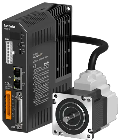
Autonics AiCA-D Series AC Power Input 2 Phase Closed Loop Stepper Motor Drivers
Product Information:
The AiCA-D Series 2-Phase Closed-loop Stepper Motor Drivers are designed to be used with machinery that requires precision control, such as medical equipment, nuclear power control, ships, vehicles, railways, aircraft, combustion apparatus, safety equipment, crime/disaster prevention devices, and more. The drivers ensure accurate and stable motor control with high torque output and smooth motion.
Safety Considerations
- Install a fail-safe device when using the unit with machinery that may cause serious injury or substantial economic loss.
- Do not use the unit in places where flammable/explosive/corrosive gas, high humidity, direct sunlight,radiant heat, vibration, impact or salinity may be present.
- Do not connect, repair, or inspect the unit while connected to a power source.
- Install the unit after considering counter plan against power failure.
- Re-supply power after a minimum of 20 seconds from disconnected power.
- Check “Connections” before wiring.
- For installing the unit, ground it exclusively and use over AWG 18 (0.75 mm2) ground cable.
- Do not disassemble or modify the unit.
- Insulate the connector not to be exposed.
- Install the driver in the housing or ground it.
- Do not touch the unit during or after operation for a while.
- Do not remove the connector during or after operation for a while.
- Emergency stop directly when an error occurs.
Cautions During Use:
- Use the product indoors only in the environment condition rated in “Specifications.”
- The altitude should be max. 2,000 m, and the pollution degree should be 2.
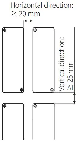
- Installation category II with a vertical direction of 25 mm and a horizontal direction of 20 mm should be maintained.
Cautions During Installation:
- Refer to the manuals for proper use of the product and follow the safety considerations in the manuals.
Product Usage:
- Ensure that the fail-safe device is installed when using the unit with machinery that may cause serious injury or substantial economic loss.
- Avoid using the unit in places where flammable/explosive/corrosive gas, high humidity, direct sunlight,radiant heat, vibration, impact or salinity may be present.
- Do not connect, repair, or inspect the unit while connected to a power source.
- Install the unit after considering counter plan against power failure.
- Wait for a minimum of 20 seconds to re-supply power after disconnected power.
- Check “Connections” before wiring to avoid fire hazards.
- Ground the product exclusively and use over AWG 18 (0.75 mm2) ground cable for installing the unit.
- Do not disassemble or modify the unit to avoid fire or electric shock.
- Insulate the connector not to be exposed to prevent electric shock.
- Install the driver in the housing or ground it to avoid personal injury, fire, or electric shock.
- Avoid touching the unit during or after operation for a while due to high temperature of the surface that may result in burn or electric shock.
- Do not remove the connector during or after operation for a while. It may result in electric shock or product damage.
- Stop the unit directly when an error occurs to avoid personal injury or fire hazards.
Cautions During Use:
- Use the product indoors only in the environment condition rated in “Specifications.”
- The altitude should be max. 2,000 m, and the pollution degree should be 2.
- Installation category II with a vertical direction of 25 mm and a horizontal direction of 20 mm should be maintained.
Cautions During Installation:
- Refer to the manuals for proper use of the product and follow the safety considerations in the manuals.
Thank you for choosing our Autonics product.
Read and understand the instruction manual and manual thoroughly before using the product.
For your safety, read and follow the below safety considerations before using. For your safety, read and follow the considerations written in the instruction manual, other manuals and Autonics website.
Keep this instruction manual in a place where you can find easily.
The specifications, dimensions, etc. are subject to change without notice for product improvement. Some models may be discontinued without notice.
Follow Autonics website for the latest information.
Safety Considerations
- Observe all ‘Safety Considerations’ for safe and proper operation to avoid hazards.
- symbol indicates caution due to special circumstances in which hazards may occur.
Warning Failure to follow instructions may result in serious injury or death.
- Fail-safe device must be installed when using the unit with machinery that may cause serious injury or substantial economic loss. (e.g. nuclear power control, medical equipment, ships, vehicles, railways, aircraft, combustion apparatus, safety equipment, crime / disaster prevention devices, etc.)
Failure to follow this instruction may result in personal injury, economic loss or fire. - Do not use the unit in the place where flammable / explosive / corrosive gas, high humidity, direct sunlight, radiant heat, vibration, impact or salinity may be present.
Failure to follow this instruction may result in explosion or fire. - Do not connect, repair, or inspect the unit while connected to a power source.
Failure to follow this instruction may result in fire or electric shock. - Install the unit after considering counter plan against power failure.
Failure to follow this instruction may result in personal injury, economic loss or fire. - Re-supply power after min. 20 sec from disconnected power.
It may cause damage or malfunction of the product - Check ‘Connections’ before wiring.
Failure to follow this instruction may result in fire. - For installing the unit, ground it exclusively and use over AWG 18 (0.75 mm2) ground cable.
Failure to follow this instruction may result in electric shock. - Do not disassemble or modify the unit.
Failure to follow this instruction may result in fire or electric shock. - Insulate the connector not to be exposed.
Failure to follow this instruction may result in electric shock. - Install the driver in the housing or ground it.
Failure to follow this instruction may result in personal injury, fire or electronic shock. - Do not touch the unit during or after operation for a while.
Failure to follow this instruction may result in burn or electric shock due to high
temperature of the surface. - Do not remove the connector during or after operation for a while.
Failure to follow this instruction may result in electric shock, or product damage. - Emergency stop directly when error occurs.
Failure to follow this instruction may result in personal injury or fire.
Caution Failure to follow instructions may result in injury or product damage.
- When connecting the power input, use AWG18 (0.75 mm2) cable or over.
- Brake is non-polar. When connecting the brake, use AWG24 (0.2 mm2) cable or over.
Failure to follow this instruction may result in fire or malfunction due to contact failure. - Install over-current prevention device (e.g. the current breaker, etc.) to connect the driver with power.
Failure to follow this instruction may result in fire. - Check the control input signal before supplying power to the driver.
Failure to follow this instruction may result in personal injury or product damage by unexpected driver movement. - Install a safety device to maintain the vertical position after turn off the power of this driver.
Failure to follow this instruction may result in personal injury or product damage by releasing holding torque of the motor. - Use the unit within the rated specifications.
Failure to follow this instruction may result in fire or product damage. - Use a dry cloth to clean the unit, and do not use water or organic solvent.
Failure to follow this instruction may result in fire or electric shock. - The driver may overheat depending on the environment.
Install the unit at the well-ventilated environment and forced cooling with a cooling fan.
Failure to follow this instruction may result in product damage or degradation by heat. - Keep the product away from metal chip, dust, and wire residue which flow into the unit.
Failure to follow this instruction may result in fire or product damage. - Use the designated motor only.
Failure to follow this instruction may result in fire or product damage.
Cautions during Use
- Follow instructions in ‘Cautions during Use’.
Otherwise, it may cause unexpected accidents. - Using USB type 485 converter may cause unstable communication. It is recommended to use 485 converter with separated power. (Autonics product SCM-38I is recommended.)
- Install vertically so that the alarm / warning status display part is located on top.
- In case of unwanted noise generating from peripherals and power, use ferrite core in the wiring.
- The thickness of cable should be same or thicker than the below specifications when connecting the cable for connector.
- Motor + Encoder connector: AWG 22
- Power connector: AWG 18
- Communication connector: AWG 28
- I/O connector: AWG 28
- Brake connector: AWG 22
- Keep the distance between power cable and signal cable over 10 cm.
- Do not input external signal until the driver is initialized (In-Position LED ON) after power is applied.
- Motor vibration and noise may occur in a specific frequency range.
- Change the motor installation method or attach the damper.
- Use the unit out of the corresponding frequency range due to changing motor RUN speed.
- Maintain and inspect regularly the following lists.
- Unwinding bolts and connection parts for the unit installation and load connection
- Abnormal sound from ball-bearing of the unit
- Damage and stress of lead cable of the unit
- Connection error with motor
- Inconsistency between the axis of motor output and the center, concentric (eccentric, declination) of the load, etc.
- This product does not contain a protection function for a motor unit.
- This unit may be used in the following environments.
- Indoors (in the environment condition rated in ‘Specifications’)
- Altitude max. 2,000 m
- Pollution degree 2
- Installation category II
Cautions during Installation
- Install on the metal plate with high thermal conductivity for heat dissipation of the driver.
- Install in the well-ventilated area and install the cooling fan in the unventilated environment.
- Failure to heat dissipation may result in damage or malfunction due to the stress on the product.
Check the environment of use within the specifications and install on the well-heat-dissipated area - In case of installing the drivers more than two, keep distance at least 20 mm in horizontal direction and at least 25 mm in vertical direction.

Manual
For proper use of the product, refer to the manuals and be sure to follow the safety considerations in the manuals.
Download the manuals from the Autonics website
Software
Download the installation file and the manuals from the Autonics website.
atMotion
The program allows to manage the motor driver’s parameter setting and monitoring data.
Ordering Information
This is only for reference, the actual product does not support all combinations..
For selecting the specified model, follow the Autonics website.
Select a model that matches the ordering information of the motor and the driver.

- Frame size
Number: Frame size (Unit: mm) - Axial length
M: Medium
L: Long - Motor type
No mark: Standard type
B: Built-in brake type
Product Components
- Product
- Instruction manual
- RS485 comm. protective connector
- Power connector
- I/O connector
- Brake connector (AiCA-D-B Series
Sold Separately
- Motor + Encoder cable: C1D14M-□ (fixed type), C1DF14M-□ (flexible type)
- I/O Cable: CO50-MP-R (specifications: AiC TAG)
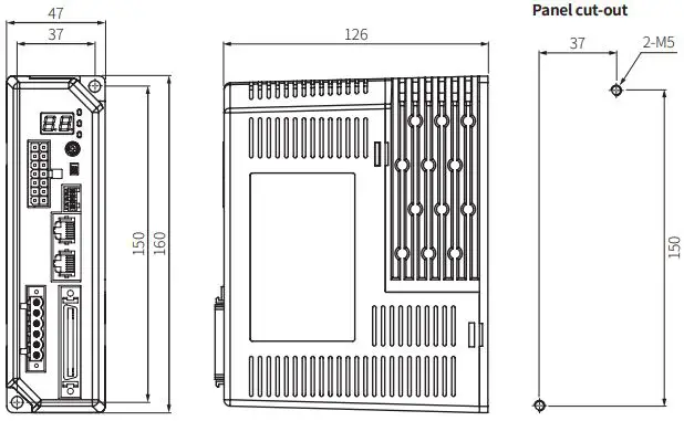
Dimensions
Unit: mm, For the detailed drawings, follow the Autonics website.
Unit Descriptions
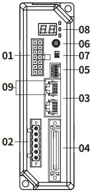
- Motor + Encoder connector
- Power connector
- Communication connector
- I/O connector
- Brake connector
- Comm. ID setting rotary switch
- Comm. ID setting / Terminating resistance DIP switch
- Status display part/indicators
- RS485 comm. indicator
Status Display Part / Indicators
| Display part / Indicator | Color | Descriptions |
| Status display part (7 segment) | Red | Displays communication ID when normal status Displays the corresponding number, operation when alarm / warning occurs |
| Power / Warning indicator (PWR/AL) | Green | Turns ON when the unit operates in normal after power is applied Flashes depending on the warning type |
| Red | Flashes depending on the alarm type | |
| In-Position indicator (INP.) | Orange | Turns ON when motor is placed at command position after positioning input Turns OFF when torque mode is ON |
| Servo ON / OFF indicator (SERVO) | Blue | Turns ON when servo is ON, Turns OFF when servo is OFF |
| RS485 Comm. indicator (RXD IN) | Yellow | Flashes when receiving data |
| RS485 Comm. indicator (TXD OUT) | Green | Flashes when transmitting data |
Alarm / Warning
The status display part displays segment depending on Alarm / Warning type.
Depending on the alarm type, it flashes for 0.4 sec interval and it turns OFF for 0.8 sec
repeatedly.
Alarm
| Display | No. of flashing | Alarm type | Display | No. of flashing | Alarm type |
| E1 | 1 | Overcurrent error | EA | 10 | Motor alignment error |
| E2 | 2 | Overspeed error | EB | 11 | Command speed error |
| E3 | 3 | Position tracking error | EC | 12 | In-Position error |
| E4 | 4 | Overload error | ED | 13 | Memory error |
| E5 | 5 | Overheat error | EE | 14 | Emergency stop |
| E6 | 6 | Motor connection error | EF | 15 | Program mode error |
| E7 | 7 | Encoder connection error | EG | 16 | Index mode error |
| E8 | 8 | Overvoltage error | EH | 17 | Home search mode error |
| E9 | 9 | Undervoltage error | EJ | 18 | Brake connection error |
Warning
| Display | No. of flashing | Warning type |
| W1 | 1 | +Software limit |
| W2 | 2 | -Software limit |
| W3 | 3 | +Hardware limit |
| W4 | 4 | -Hardware limit |
| W5 | 5 | Overload warning |
| W6 | 6 | Override warning |
Specifications
| Model | AiCA-D-60MA-□ | AiCA-D-60LA-□ | AiCA-D-86MA-□ | AiCA-D-86LA-□ | |
| Main | Power supply | 200 – 240 VACᜠ 50 / 60 Hz | |||
| Max. RUN power01) | ≤ 800 VA | ||||
| Stop power 02) | ≤ 60 VA | ≤ 65 VA | |||
| AUX 03) | Power supply | 24 VDCᜡ | |||
| Input current | 0.3 A | 0.5 A | |||
| Max. RUN current04) | 2.0 A / Phase | ||||
| Stop current | 20 to 100% of max. RUN current | ||||
| Resolution | 500 (factory default), 1000, 1600, 2000, 3200, 3600, 5000, 6400, 7200, 10000 PPR | ||||
- When changing the load rapidly, instantaneous peak current may The capacity of power supply should be over 1.5 to 2 times of max. RUN power.
- Based on ambient 25℃, ambient humi. 55%RH, stop current 50%
- Auxiliary power is only available in built-in brake type and not available in standard
- RUN current varies depending on the input RUN frequency and max. RUN current at the moment varies also
| Run method | 2-phase bipolar closed-loop control method |
| Speed filter | Disable, 2, 4, 6, 8, 10, 20, 40, 60 (factory default), 80, 100, 120, 140, 160, 180, 200 ms |
| Control Gain | 0 (factory default) to 30, Fine Gain |
| Max. rotation speed | 3000 rpm |
| Position setting range | -2,147,483,648 to +2,147,483,647 |
| In-Position | Fast Response: 0 (factory default) to 7, Accurate Response: 0 to 7 |
| Rotation direction | CW (factory default), CCW |
| Operation mode | Jog mode, Continuous mode, Index mode, Program mode |
| Home search mode | General mode, Limit mode, Zero point mode, Torque mode |
| Index step | 64 step |
| Program step | 256 step |
| Program function | Power On Program Start, Power On Home Search |
| Control command | ABS, INC, HOM, ICJ, IRD, OPC, OPT, JMP, REP, RPE, END, POS, TIM, CMP, TOQ |
| I/O voltage level | [H]: 5 – 30 VDCᜡ, [L]: 0 – 2 VDCᜡ |
| Input 01) | Exclusive input: 20, General input: 9 |
| Output | Exclusive output: 4, General output: 10 |
| External power supply | VEX (24 VDCᜡ fixed): 2, GEX (GND): 2 |
| Input resistance | 4.7 kΩ (Anode Pull-up) |
| Insulation resistance | ≥ 200 MΩ (500 VDCᜡ megger) |
| Dielectric strength | 1,500 VACᜠ 60 Hz for 1 minute |
| Vibration | 1.5 mm double amplitude at frequency 10 to 55 Hz (for 1 minute) in each X, Y, Z direction for 2 hours |
| Shock | 300 m/s2 (≈ 30 G) in each X, Y, Z direction for 3 times |
| Ambient temp. | 0 to 50℃, storage: -10 to 60℃ (no freezing or condensation) |
| Ambient humi. | 35 to 85%RH, storage: 10 to 90%RH (no freezing or condensation) |
| Protection rating | IP20 (IEC standard) |
| Approval | ᜢ ᜥᜫ |
| Unitweight(packaged) | ≈ 780 g (≈ 1,050 g) |
Brake ON/OFF function can be changed from general input IN8 in case of built-in brake type
Communication Interface
RS485
| Comm. protocol | Modbus RTU |
| Applied standard | Compliance with EIA RS485 |
| Max. connections | 31 units (address: 01 to 31) |
| Synchronous method | Asynchronous |
| Comm. method | 2-wire half duplex |
| Comm. distance | ≤ 800 m |
| Baud rate | 9600, 19200, 38400, 57600, 115200 (factory default) bps |
| Start bit | 1 bit (fixed) |
| Data bit | 8 bit (fixed) |
| Parity bit | None (factory default), Even, Odd |
| Stop bit | 1 bit (factory default), 2 bit |
Power Supply Configuration Diagram
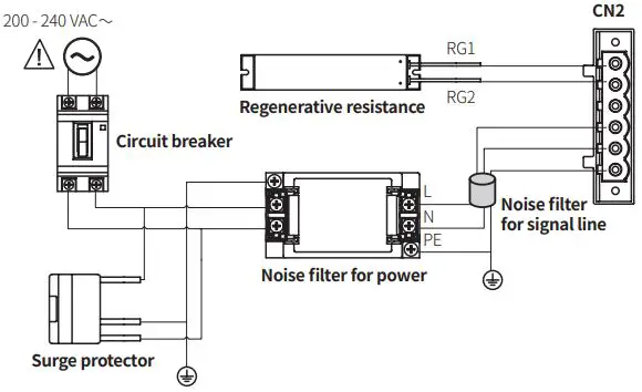
Noise filter for signal line
Connect to wiring to suppress external noise.
Depending on frequency, filtered noise may different
| Type | Model | Manufacture |
| Motor line, I/O signal line | 28A5776-0A2 | Lairdtech |
| Power line | 28A5131-0A2 | |
| Communication line | 28A2025-0A2 |
Noise filter for power
Connect the power to suppress external noise.
The wires should be connected as short as possible and grounded
| Model | Specifications | Manufacture |
| RNS-2006 | Rated voltage: 250 V Rated current: 6 A Max. leakage current: 1 mA | Orient Electronics |
Regenerative resistance
Connect the pin 1, 2 on the power connector.
Use in condition of the high inertia load or the short deceleration time.
Forced cooling is required in condition of high surface temperature of regenerative resistance.
| Model | Specifications | Manufacture |
| IRC100 | Resistance: 100 Ω ±5%, Rated power: 60 W (standby), 100 W (heatsink attached) | Rara Electronics Corp. |
Surge protector
Protect the product from external noise and surge by connecting power. Be sure to disconnect the surge protector when testing internal pressure. It may result in product damage.
| Model | Specifications | Manufacture |
| LT-C12G801W | Nominal discharge current: 2500 A Max. discharge current: 5000 A Voltage protection level: 1.5 kV | OTOWA Electric Co. Ltd |
Troubleshooting
| Malfunction | Causes | Troubleshooting |
|
When communication is not connected | The communication cable is not connected. | Check communication cable wiring. Check communication cable connected correctly. |
| The communication port or speed settings are not correct. | Check communication port and speed settings are correct. | |
| When motor does not excite | Servo is not ON. | Check that Servo ON/OFF input signal is OFF. In case of ON, servo is OFF and excitation of motor is released. |
| Alarm occurs. | Check the alarm type and remove the cause. | |
| When motor rotates to the opposite direction of the designated direction | MotorDir parameter setting is not correct. | Check the MotorDir parameter settings. |
| When motor drives unstable | Connection between motor and encoder is unstable. | Check the driver and motor are connected correctly. |
| Control Gain value is not correct. | Change the Control Gain parameter as the appropriate value. |


